Advertisement
Quick Links
Sep . 2 0 1 0
Ta b le o f Co n ten ts
Cau tionary N otes ..............................................................2
Sp ecifications .....................................................................2
Location of Controls .........................................................3
Location of Controls Parts List ........................................3
Exp lod ed View ..................................................................4
Exp lod ed View Parts List.................................................4
Im p ortant N otes on Assem bly ........................................5
Parts List .............................................................................6
Verifying the Version........................................................8
Co p y r ig h t
2 0 1 0 Ro la n d Co r p o r a tio n
All rights reserved. No part of this publication may be reproduced in any form without the written permission
of Roland Corporation.
Data Backu p and Restore Op erations ............................8
Perform ing a Factory Reset ..............................................8
Up d ating the System ........................................................8
Op eration Test ...................................................................8
Circu it Board (Main, VR, Inp u t, Ou tp u t, SW, LED
Board )................................................................................12
Circu it Diagram (Main, VR, Inp u t, Ou tp u t, SW, LED
Board )................................................................................14
Revice Information
Oct. 18, 2011
17058696E0
SERVICE N O TES
Issued by RJA
P.3
Ad d ed an accessory
ST-2
CC-KWS
Advertisement

Subscribe to Our Youtube Channel
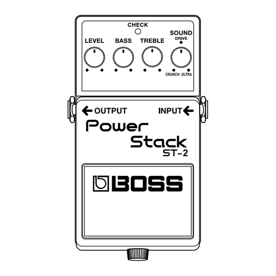
Summary of Contents for Roland PowerStack ST-2
- Page 1 Co p y r ig h t 2 0 1 0 Ro la n d Co r p o r a tio n All rights reserved. No part of this publication may be reproduced in any form without the written permission of Roland Corporation. 17058696E0 CC-KWS...
- Page 2 Becau se the p art is m ad e to ord er (at cu rrent m arket p rice). Carbon: 3 hou rs Becau se it is carried in electronic d ata on the Roland w eb site. Alkaline: 9 hou rs Becau se it is a p ackage or an accessory irrelevant to the fu nction m aintenance of the m ain bod y.
- Page 3 Sep . 2 0 1 0 ST-2 Lo ca tio n o f Co n tr o ls fig.panel.eps Lo ca tio n o f Co n tr o ls Pa r ts List Part Code Part Name Description Q'ty 5100014487 COMPACT PSA LABEL (22537538R0)
- Page 4 Sep . 2 0 1 0 ST-2 Ex p lo d ed View fig.bunkaizu.eps Ex p lo d ed View Pa r ts List Part Code Part Name Description Q'ty 13129710R0 SWITCH (PUSH ) JM-0404 5100007503 BATTERY CUSH ION (22267333R0) 5100007872 BATTERY CON N ECTOR 006P BATTERY SN AP (F3419102R0...
- Page 5 Sep . 2 0 1 0 ST-2 Im p o r ta n t N o tes o n A ssem b ly Input-board Wiring Orientation of the VR Board Oscillation noise is p rod u ced if the Inp u t-board w ires (brow n and black) When installing the VR Board, be carefu l not to orient it incorrectly, com e near the CODEC, as show n in the figu re.
- Page 6 Sep . 2 0 1 0 ST-2 Pa r ts List fig.-part1-e.eps Due to one or more of the following reasons, Safety Precautions: parts with parts code ******** cannot be supplied as service parts. The parts marked have safety-related characteristics. Use only listed parts for replacement.
- Page 7 Sep . 2 0 1 0 ST-2 MISCELLANEOUS 5100006330 EARTH TERMIN AL (22257257R0) 5100006633 BOTTOM FOOT (22357305R0) 5100007503 BATTERY CUSH ION (22267333R0) 5100007504 COIL SPRIN G (22177109R0) 5100007505 PEDAL GUIDE BUSH (22157702R0) 5100007509 IN SULATIN G SH EET (75D273W0R0) 5100007870 IN SULOCK TIE YJ-80 V2 (H 5319102R0) 5100006631...
- Page 8 Sep . 2 0 1 0 ST-2 Ver if y in g th e Ver sio n O p er a tio n Test Tu rn all controls all the w ay cou nterclockw ise. Items Required H old d ow n the p ed al and insert a 1/ 4-inch stereo p hone p lu g into the INPUT jack.
- Page 9 Sep . 2 0 1 0 ST-2 1. Measurement of Current Consumption 3. Analog Volume Test Make the connections as show n in the figu re, then start the u nit in the Make the connections as show n in the figu re below , then start the u nit in Test Mode.
- Page 10 Sep . 2 0 1 0 ST-2 5. BYPASS Test Make the connections as show n in the figu re below , then start the u nit in the normal usage state. fig.test-5.eps PSA- ADAPTOR Dep ress the p ed al to m ake the CHECK LED go d ark. The effect is sw itched off.
- Page 11 Sep . 2 0 1 0 ST-2...
- Page 12 Sep . 2 0 1 0 ST-2 Cir cu it Bo a r d (M a in , VR, In p u t, O u tp u t, SW , LED Bo a r d ) fig.b-main-1.eps...
- Page 13 Sep . 2 0 1 0 ST-2 fig.b-main-2.eps...
- Page 14 Sep . 2 0 1 0 ST-2 Cir cu it Dia g r a m (M a in , VR, In p u t, O u tp u t, SW , LED Bo a r d ) fig.d-main.eps@L ST-2 (BG640) circuit 2SC4117-GR(TE85L.F) ASSY No.********R0 D ( 0.5% )
- Page 15 Sep . 2 0 1 0 ST-2 fig.d-main.eps@R TP43 4.7uF 35V 2SK879-Y(TE85R.F) 4.7uF 35V TP25 OUTPUT BOARD TP128 10uF 470k TP75 TP143 470k 470k TP95 TP144 TP76 1SS387(TPH3.F) 100k 150pF TP96 TP99 HTJ-064-13D BYPASS-MUTE AGND 0.027uF AGND AGND AGND DTC114TUAT106 NJM4580M(TE1) AGND DGND...


Need help?
Do you have a question about the PowerStack ST-2 and is the answer not in the manual?
Questions and answers