Roland S-4000S Owner's Manual
Roland s-4000s sound processor: owners manual
Hide thumbs
Also See for S-4000S:
- Quick start manual (4 pages) ,
- Installation manual (2 pages) ,
- Specification (2 pages)
Table of Contents
Advertisement
S-4000
S-4000S 40 CH I/O MODULAR RACK
S-4000H FOH UNIT
S-4000R REMOTE CONTROLLER
Owner's Manual
Before using this unit, carefully read the sections entitled: "IMPORTANT SAFETY
INSTRUCTIONS" (S-4000S Owner's Manual Pg. 2), "USING THE UNIT SAFELY"
(S-4000S Owner's Manual Pg. 3), and "IMPORTANT NOTES" (S-4000S Owner's Manual
Pg. 7). These sections provide important information concerning the proper operation
of the unit. Additionally, in order to feel assured that you have gained a good grasp of
every feature provided by your new unit, S-4000S Owner's Manual should be read in its
entirety. The manual should be saved and kept on hand as a convenient reference.
Copyright © 2005 ROLAND CORPORATION
All rights reserved. No part of this publication may be reproduced in any form without
the written permission of ROLAND CORPORATION.
http://www.RSSAmerica.com/
Advertisement
Table of Contents

Related Manuals for Roland S-4000S


Summary of Contents for Roland S-4000S
- Page 1 Additionally, in order to feel assured that you have gained a good grasp of every feature provided by your new unit, S-4000S Owner’s Manual should be read in its entirety. The manual should be saved and kept on hand as a convenient reference.
-
Page 2: Important Safety Instructions
�������� �� ������ ��� ���� �� ���� �� �������� ������ �� ��� ������ ���� ��������� �� ���� �� ��������� ��� ��������� ����� ���� ��������� ������� ������ �� ������� ����������� ��������� �� �������� �� ����� ��� ���� �� ��� ���� �� �������� ����� ��������... -
Page 3: Using The Unit Safely
Refer ��� • This unit, either alone or in combination with an all servicing to your retailer, the nearest Roland amplifier and headphones or speakers, may be Service Center, or an authorized Roland capable of producing sound levels that could distributor, as listed on the "Information"... - Page 4 • The unit should be located so that its location or power cord from the outlet, and request servicing position does not interfere with its proper venti- by your retailer, the nearest Roland Service lation. Center, or an authorized Roland distributor, as ����������������������������������������������������������������������������������������������������������...
- Page 5 Be sure to check the specifications of any microphone or other device you intend to use by referring to the documentation that came with it. (The S-4000S phantom power specification: +48 V DC, 14 mA Max.) ���������������������������������������������������������������������������������������������������������� S-4000 Digital Snake Owner’s Manual...
- Page 6 Using the Unit Safely S-4000 Digital Snake Owner’s Manual...
-
Page 7: Important Notes
Important Notes In addition to the items listed under IMPORTANT • Noise may be produced if wireless communications SAFETY INSTRUCTIONS (Page 2) and USING THE devices, such as cell phones, are operated in the UNIT SAFELY (Page 3), please read and observe the vicinity of this unit. - Page 8 Important Notes • When you need to transport the unit, package it in the box (including padding) that it came in, if possible. Otherwise, you will need to use equivalent packaging materials. S-4000 Digital Snake Owner’s Manual...
-
Page 9: Table Of Contents
S-4000S 40 CH I/O Modular Rack ........ - Page 10 Rack-Mounting the S-4000R ........... . 45 Using the REAC Connector Covers (S-4000S and S-4000H) ......46 Installing the Included Ferrite Cores on Ethernet Cables .
- Page 11 S-4000S Input Channel Settings ........
- Page 12 S-4000S XLR Audio Pin Outs (INPUT and OUTPUT) ....... 89...
-
Page 13: 1-Introduction
Welcome Congratulations on your purchase of the RSS S-4000 Digital Snake System. Featuring the new REAC (Roland Ethernet Audio Communication) interface, the S-4000 System brings the audio snake into the digital age. The S-4000 System is designed to be extremely easy to configure and set up, and is at home in any application where multichannel audio transfer is required. -
Page 14: Conventions Used In The Manual
S-4000R Remote Controller Throughout the text, the individual components’ names are often shortened, and referred to simply as “S-4000S,” “S-4000H,” and “S-4000R.” When a procedure or description refers to the entire system, the name “S-4000 System” is used. Additionally, the names of buttons, knobs, and connectors are shown exactly as they appear on the system components. -
Page 15: Note, Tip, And Warning Icons
1—Introduction Note, Tip, and Warning Icons Throughout the S-4000 Digital Snake Owner’s Manual, you’ll occasionally come across areas highlighted in gray that provide extra information related to the feature or operation described in the main text. The symbols in the left-hand margin define the nature of this extra information. A note is something that adds information about the topic at hand. - Page 16 1—Introduction S-4000 Digital Snake Owner’s Manual...
-
Page 17: 2-Main Features
MUTE ALL OUTPUTS button for noise-free connection of audio sources • Connection port for optional redundant power supply S-4000R Remote Controller • Simple, easy-to-use remote control unit • Provides control of preamp gain, phantom power, and pad for each S-4000S input channel S-4000 Digital Snake Owner’s Manual... - Page 18 2—Main Features • Smooth and clean input gain adjustment (1 dB steps) • Ten memory presets for storing frequently used input setups • Eight-segment LED meter for precise input signal level monitoring • Signal status indicators for all 40 channels •...
-
Page 19: 3-Components And Accessories
1—S-4000H Installation Manual 1—S-4000R Installation Manual Audio is transferred between the S-4000S and S-4000H via REAC. A single cable REAC-to-REAC device connection requires a Cat5e Ethernet cable wired in a crossover configuration. The included Cat5e crossover cable is 10 meters in length, and is appropriate for testing and small installations. -
Page 20: System Options
3—Components and Accessories System Options These items are available system options: • S-4000 Remote Control Software (S-4000 RCS)—Computer control software for PC/Mac (free download from www.RSSAmerica.com) • SC-A0805DM—4.5 meter male breakout cable to connect S-4000H outputs to audio destinations (DB-25 connector to 8 male XLR connectors) •... -
Page 21: 4-Panel Descriptions
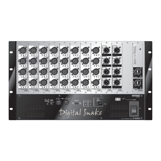
SIG—lights green when the input signal is greater than -40 dB (after A/D conversion). The S-4000S includes eight SI-AD4 Input Modules, providing a total of 32 input channels. Preamp gain adjustment and phantom power status can be controlled from the S-4000R Remote Controller or from a computer using the S-4000 RCS. - Page 22 3—REAC Module (S-REAC2) The S-REAC2 Module has two REAC ports for connecting the S-4000S to another REAC device or an Ethernet switching hub. These ports use Neutrik® EtherCon® RJ45 connectors for a robust connection. Standard RJ45 plugs can be connected here as well.
- Page 23 Troubleshooting for more information. 10—POWER Switch Use the POWER switch to turn the internal power supply of S-4000S on and off. When receiving power from an S-240P External Power Supply Unit, the S-4000S will work even if the POWER switch is in the OFF position.
-
Page 24: S-4000S Rear Panel
The S-4000S contains cooling fans that prevent the unit from overheating. The air intake vents provide fresh air for the cooling fans. Be sure never to block the air intake vents. Doing so may cause the S-4000S to overheat and be damaged. -
Page 25: S-4000H 32X8 Foh Unit
The S-4000S contains cooling fans that prevent the unit from overheating. The fans expel hot air through these vents. Be sure never to block the cooling fan exhaust vents. Doing so may cause the S-4000S to overheat and be damaged. - Page 26 4— Panel Descriptions 2—REAC MODE Switch This switch sets the S-4000H’s REAC device behavior. • M—This configures the S-4000H as a Master REAC device. • S—This configures the S-4000H as a Slave REAC device. • SP—This configures the S-4000H as a Split REAC device. The REAC MODE switches must be set properly for the system to work.
- Page 27 4—Panel Descriptions Press and hold the MUTE ALL OUTPUTS button. After approximately 1.5 seconds, its indicator lights. While the indicator is lit, the audio outputs of all connected REAC devices are muted. The system outputs will become un-muted a few seconds after MUTE ALL OUTPUTS is released. If audio is passing through the system when MUTE ALL OUTPUTS is released, the sound may be distorted until the system outputs are completely un-muted.
-
Page 28: S-4000H Rear Panel
4— Panel Descriptions S-4000H Rear Panel � � � � 1—INT. POWER AC INPUT Jack Connect one end of the supplied AC power cord to a grounded AC outlet, and the other end to the INT. POWER AC INPUT jack to provide power for the S-4000H’s internal power supply. Use the cord restraint to prevent the power cord from being accidentally pulled out. -
Page 29: S-4000R Remote Controller
� � 1—Memory Buttons The S-4000R provides ten memory presets for storing S-4000S input channel settings. Use the RECALL and STORE buttons to recall and store settings. See Page 70 to learn how to recall and store memory presets. 2—CHANNEL Knob and LED Display Use the CHANNEL knob to select an input channel for editing or signal level monitoring. - Page 30 Use this knob to set the preamp gain for the currently selected S-4000S input channel. Indicator lights surrounding the GAIN knob show the current gain setting. Each S-4000S input channel’s gain range is -45 to +10 dBu with the pad on, and -65 to -10 dBu with the pad off.
-
Page 31: S-4000R Rear Panel
REAC—This indicator lights when REAC communication is established within the S-4000 System. If REAC communication fails, this indicator will flash. • CTRL—This indicator lights when the S-4000R is connected to a powered on S-4000S or S-4000H and communication is established. S-4000R Rear Panel �... - Page 32 4— Panel Descriptions S-4000 Digital Snake Owner’s Manual...
-
Page 33: 5-S-4000 System Overview
S-4000 System Overview Concept The S-4000 System brings the digital revolution to the world of audio snakes. Using computer networking technology, the system allows you to transfer 40 channels of high-quality audio over an extremely long distance on a single lightweight cable. The digital advantage also brings with it easy installation, low cost, portability, and pain-free expansion. -
Page 34: Things To Know
Things to Know About At the heart of the S-4000 System is the REAC (Roland Ethernet Audio Communication) interface. This proprietary protocol is based on the Ethernet technology that’s used in computer networks, and allows for the transfer of up to 40 channels of digital audio over a single Cat5e Ethernet cable. -
Page 35: Ethernet Connectors
5—S-4000 System Overview • Straight-through cables should be used when an Ethernet switching hub is integrated into the system for cable length extension or split applications. (We’ll discuss switching hubs a little later.) Ethernet connection standards recommend using straight-through cables to connect devices to the ports on a switching hub, and crossover cables when connecting hub-to-hub. -
Page 36: About Ethernet Switching Hubs
5—S-4000 System Overview About Ethernet Switching Hubs An Ethernet switching hub—sometimes referred to simply as a “switch”—is an interface that allows multiple devices (called “nodes” in Ethernet lingo) to communicate with each other in an Ethernet network. The switching hub has multiple ports with RJ45 receptacles, and each network device is connected to one of these ports. -
Page 37: Built-In Redundant Connections
Additionally, the S-4000S provides variable gain preamps on each of its 32 audio inputs. This allows for signal optimization at the source, resulting in the highest A/D conversion quality. -
Page 38: Optional Redundant Power Supply
S-4000S’s inputs. After all, you have gain adjustment at the console inputs, right? Well, there are a few very good reasons to adjust the signal level at the S-4000S inputs: S-4000 Digital Snake Owner’s Manual... -
Page 39: S-4000H 32X8 Foh Unit
The S-4000H is the front-of-house (FOH) connection interface for the S-4000 System. As such, its I/O configuration is the opposite of the S-4000S—8 audio inputs and 32 audio outputs. As it name suggests, the S-4000H FOH Unit’s main application is near the FOH mixing console. -
Page 40: S-4000R Remote Controller
• Input level monitoring—An eight-segment LED meter allows for precise preamp gain adjustment of the S-4000S’s input channels. Additionally, the meter can be used to view signal levels from the S-4000H’s audio inputs. • Signal status—The S-4000R provides signal status indicators for all of the S-4000 System’s 40 input channels. -
Page 41: 6-Using The S-4000 System
Recessed Rack-Mounting If desired, the rack-mount brackets on the S-4000S and S-4000H units can be reinstalled so that the units’ face plates are recessed when mounted in a rack. This can be useful for protecting the front panel connections in high-traffic installations, as the connectors plugged into the various inputs and outputs will not protrude from the face of the rack. - Page 42 Use the following procedure to remove and reinstall the S-4000S’s rack-mount brackets for recessed rack-mounting. Turn off the power on all equipment and disconnect all cables from the S-4000S unit. Remove only the screws shown in the following diagram (12 screws total), and detach the rack- mount bracket from one side of the unit as shown.
- Page 43 6—Using the S-4000 System Recessed Rack-Mounting: S-4000H Use the following procedure to remove and reinstall the S-4000H’s rack-mount brackets for recessed rack-mounting. Turn off the power on all equipment and disconnect all cables from the S-4000H unit. Remove only the screws shown in the following diagram (6 screws on each side, 12 screws total), and detach the rack-mount brackets from the sides of the unit as shown.
-
Page 44: Connector Guard (S-4000H Only)
6—Using the S-4000 System DB-25 Connector Guard (S-4000H Only) Install the slide-on connector guard on the S-4000H front panel to provide protection for the DB-25 input and output connectors. When installed, the connector guard will support DB-25 connectors that are plugged in the front panel, and prevent them from being bent due to accidental stress or the weight of the connector’s cable. -
Page 45: Rack-Mounting The S-4000R
6—Using the S-4000 System Rack-Mounting the S-4000R The S-4000R Remote Controller is designed for handheld or desktop use. If desired, it can be rack- mounted by installing the included rack-mount brackets. Use the following procedure to install the rack-mount brackets on the S-4000R. Disconnect the RS-232C cable from the S-4000R unit. -
Page 46: Using The Reac Connector Covers (S-4000S And S-4000H)
Using the REAC Connector Covers (S-4000S and S-4000H) The REAC ports on the S-4000S and S-4000H units feature rugged Neutrik® EtherCon® connectors. As discussed in Chapter 5, they can accept either standard RJ45 plugs or RJ45 plugs housed in EtherCon- type connectors. -
Page 47: Installing The Included Ferrite Cores On Ethernet Cables
6—Using the S-4000 System Installing the Included Ferrite Cores on Ethernet Cables Four ferrite cores are included with the S-4000 System for installation on Ethernet cables. Install a ferrite core on the Ethernet cable near the RJ45 plug that will be connected to a REAC port. Use the following procedure to install a ferrite core on an Ethernet cable. -
Page 48: Connection Overview
6—Using the S-4000 System Connection Overview ������� ���� ������� ���� ������� � ������� ���� ������� �� �������� ������ ������ ��������� �� ������� �� ������� ����� ����� �� ������ �� ��������� ������� RS-232C cable S-4000H 8x32 (Slave REAC device) S-4000R Remote Controller �... -
Page 49: Setting The Reac Mode
6—Using the S-4000 System Setting the REAC Mode The S-4000S and S-4000H each feature a REAC MODE switch. This switch sets the REAC behavior of each device, and determines how audio is transferred throughout the system. Each unit’s REAC MODE switch must be set properly for correct system operation. -
Page 50: Setting The Reac Mode Switches
Use only the supplied power cords to prevent damage to the units. An optional S-240P External Power Supply Unit can be used to supply redundant backup power to an S-4000S or S-4000H unit. Visit www.RSSAmerica.com or contact an RSS dealer for more information. -
Page 51: Reac Connections
6—Using the S-4000 System REAC Connections Cable Requirements A single cable REAC-to-REAC connection requires a standard Cat5e Ethernet cable with RJ45 plugs wired in a crossover configuration. The maximum length for a single cable is 100 meters (330 feet). ��������������������� �������... -
Page 52: Connecting Cables To The Reac Ports
For the primary REAC-to-REAC connection: • Connect one end of a Cat5e crossover cable (such as the one included with S-4000 System) to the MAIN REAC port on the S-4000S, and the other end to the MAIN REAC port on the S-4000H. �������... -
Page 53: Reac Cable Length Extension
If an Ethernet switching hub with at least four ports is used in-line for cable length extension, the S-4000S and S-4000H MAIN and BACKUP REAC ports can be connected to the ports on a single hub. The proper signal negotiation will be handled within the switching hub. (See the diagram on the following page.) -
Page 54: Reac Connection Notes
REAC Connection Notes • The REAC connection can be “hot-swapped”—that is, connections can be made when the S-4000S and S-4000H units are powered on. • The system is designed so that operation will inaudibly switch to the BACKUP REAC port should the MAIN REAC connection fail. -
Page 55: Connecting The S-4000R Remote Controller
The REMOTE connections can be hot-swapped—that is, connections can be made when the S-4000S and S-4000H units are powered on. This allows you to move the S-4000R from stage to FOH without shutting down the system’s power first. -
Page 56: Audio Connections
������������������� ����� ��������������� The S-4000S’s balanced audio I/O is provided on XLR-type jacks. The wiring diagram for these jacks is shown in the following illustration. Make connections after first checking the wiring diagrams of other equipment you intend to connect. -
Page 57: S-4000S Audio Inputs
S-4000S’s input and output modules. S-4000S Audio Inputs The S-4000S’s audio inputs are used to send source audio signals to the S-4000H’s audio outputs. Connect the output of balanced audio devices (microphones, instrument outputs, etc.) to the 32 balanced audio inputs on the S-4000S front panel. -
Page 58: Input Status Indicators
Connect the S-4000S’s eight balanced audio outputs to the balanced audio inputs of the desired devices. If you need to connect the S-4000S’s audio outputs to unbalanced devices, use a direct box or balancing adaptor in-line, or a cable adaptor with the wiring described in the previous section (S-4000S Audio Inputs). -
Page 59: S-4000H Audio Connections
DB-25 input wiring. S-4000H Audio Inputs The S-4000H’s audio inputs are used to send source audio signals to the S-4000S’s audio outputs. Connect the sending device’s balanced line level (+4 dBu) outputs to the S-4000H’s balanced audio inputs. -
Page 60: Powering Up/System Status Indicators
Turn on any devices connected to the S-4000S and S-4000H units’ audio inputs. Turn on the front panel power switches on the S-4000S and S-4000H units so that their INT indicators light. The S-4000S and S-4000H units are equipped with protection circuits. A brief interval (a few seconds) after power up is required before the units will operate normally. -
Page 61: Checking The System Status Indicators
6—Using the S-4000 System Checking the System Status Indicators The S-4000S, S-4000H, and S-4000R have system status indicators that allow you to monitor the integrity of the component connections when the system is powered up. Power Indicators S-4000S/S-4000H • INT—This indicator lights when the unit is receiving power from its internal power supply. -
Page 62: Remote Communication
If an S-240P External Power Supply Unit is providing power to an S-4000S or S-4000H, the S-4000S or S-4000H unit will keep operating even if the front panel power switch is in the OFF position. S-4000 Digital Snake Owner’s Manual... -
Page 63: Muting The System Outputs
��������� System’s audio outputs. On the S-4000S or S-4000H front panel, press and hold the MUTE ALL OUTPUTS button. After approximately 1.5 seconds, its indicator will light. No sound is output while the indicator is lit. When you have finished making input connections to the unit, release MUTE ALL OUTPUTS. -
Page 64: Using The S-4000R Remote Controller
See Chapter 7 for more about split setups. In the following sections, we’ll show you how to use the S-4000R’s functions. Before proceeding, make sure that the S-4000R is connected to the S-4000S or S-4000H as described on Page 55. Lock Mode The S-4000R has a Lock mode that blocks the editing of S-4000S input channels. -
Page 65: Monitoring Input Signals
Signal Status Indicators The S-4000R has two rows of signal status indicators that allow you to monitor the signal activity on the S-4000 System’s 40 audio inputs (1-32 for the S-4000S and 33-40 for the S-4000H). • SIG—lights green when the input signal level is higher than -40 dB on a particular channel. -
Page 66: Led Input Meter
CLIP will light when the signal exceeds 0 dB. S-4000S Input Channel Settings With the S-4000R unlocked, use the following procedures to adjust settings on the S-4000S input channels. To retain your changes to the S-4000S input channel settings, lock the S-4000R before powering down the S-4000 System. -
Page 67: Setting The Preamp Gain
6—Using the S-4000 System Setting the Preamp Gain Use the following procedure to set the preamp gain on an S-4000S input channel: Select the desired channel (1-32) with the CHANNEL knob. Send an input signal to the selected channel. While viewing the input level on the LED input meter, use the GAIN knob to adjust the preamp gain to the desired level. -
Page 68: Phantom Power
Phantom Power Each of the S-4000S’s inputs can supply +48 V phantom power to devices that require it, such as condenser microphones or active direct boxes. Always turn the phantom power off when connecting any device other than condenser microphones that require phantom power. -
Page 69: Stereo Link
6—Using the S-4000 System Stereo Link The Stereo Link function allows you to link odd/even adjacent S-4000S input channel pairs (1/2, 3/4, etc.). When channels are linked, gain and pad settings made on one channel of the linked pair will be duplicated on the other. -
Page 70: Memory Function
The S-4000R features 10 user-storable memory presets. A memory preset contains channel settings (preamp gain, pad, phantom power, and stereo link) for all of the S-4000S’s 32 input channels. Using memory presets, you can quickly reconfigure the S-4000S for frequently used audio input setups. -
Page 71: 7-Advanced Use
Using Two S-4000R Units in a Single S-4000 System As discussed in Chapter 6, the S-4000R can be connected to either the S-4000S or S-4000H. However, if you have a second S-4000R (available separately), you can connect one to each unit. This allows for control and signal monitoring of the S-4000 System at the location of either S-4000 unit. -
Page 72: Computer Control (S-4000 Rcs)
Functionally, using the S-4000 RCS is similar to using the S-4000R Remote Controller, but with the conveniences provided by a personal computer. S-4000 RCS features: • S-4000S input channel control screen—View and adjust settings for all S-4000S channels from one screen. • Comprehensive input level meter screen—View input activity of all input channels from one screen. -
Page 73: System Expansion
S-4000 System to an RS-232C port on the personal computer running the S-4000 RCS. See the previous section for information on the S-4000 RCS. To identify S-4000S channels, use the included adhesive-backed number label sheets to affix channel numbers to the S-4000S units’ front panel inputs and outputs. -
Page 74: Splitting Stage Audio To Multiple Destinations
Besides this setup convenience, REAC splits provide pristine audio quality—once the input signals are converted to digital data in the S-4000S, they can be split as many times as you wish with absolutely no loss in quality. -
Page 75: Split Connection Overview
7—Advanced Use Split Connection Overview �������� ��������� ��� ������� ���� (Master REAC device) � ������� ����� ���� ������� ������ S-4000H 8x32 (Split REAC device) �� �������� ������ 32 mic/line sources from the stage Monitor Console ������ ��������� �� ������� �� ������� �����... -
Page 76: Setting The Reac Mode Switches
REAC Connections For the primary REAC connections: • Using Cat5e straight-through cables, connect the MAIN REAC ports on the S-4000S/H units to ports on the switching hub. For the redundant REAC connections: •... -
Page 77: Audio Connections And Power Up
An S-4000R can be connected to the REMOTE connector on a Split REAC device. However, it can only be used for system and signal level monitoring—adjustment of S-4000S inputs is not possible. (If you need to adjust the signal level coming from a Split device’s outputs, use the input trim controls on the receiving device.) -
Page 78: Midi Communication Via Reac
MIDI OUT connector of the Master REAC device. • When an S-4000S or S-4000H is set as a Split REAC device, its MIDI IN connector is disabled. • A Split REAC device can only receive MIDI data from a Master REAC device (MIDI data reception from a Slave REAC device is not possible). -
Page 79: 8-Applications
Applications 32x8 System S-4000S 32x8 (Master) S-4000H 8x32 (Slave) S-4000 Digital Snake Owner’s Manual... -
Page 80: 32X8 System With 32 Channel Split
8—Applications 32x8 System with 32 Channel Split �������� ��������� ��� ������� ���� �������� ������� ���� ������� ������� ���� ������� S-4000 Digital Snake Owner’s Manual... -
Page 81: 64X16 System
8—Applications 64x16 System ��� ������� ���� �������� �� ������� ���� ������� �� �������� ������ ����� ������ �� ������ �� ��������� ������� ��� ������� ���� ������� �� �������� ������� �� ������� ���� ������� ���� ����� S-4000 Digital Snake Owner’s Manual... -
Page 82: 64X16 System With 64 Channel Split
8—Applications 64x16 System with 64 Channel Split ��� �������� ��� ������� ���� �������� ��������� ��� �� ������� ���� ������� ����� ������ �� �������� ����� ��� ������� ���� ������� �� �������� ������� ������� ���� ����� ������� ����� ������ �� ������ �� ��������� ������ ���... -
Page 83: Appendices
Additionally, the units provide error indicators that let you know whenever a potentially serious problem is detected in the system. The following tables show the meaning of the various status and error indicators, and suggest actions for troubleshooting and safe system operation. S-4000S and S-4000H Units: System Status Indicators Indicator Status Definition... - Page 84 Appendices S-4000S and S-4000H Units: System Status Indicators Indicator Status Definition Troubleshooting Action REAC Communication is • None (normal operation) established Dark System power-up • None (normal operation) Flashing No REAC • Make sure all REAC devices are turned on communication •...
- Page 85 Appendices S-4000R Unit: System Status Indicators Indicator Status Definition Troubleshooting Action POWER Power is received • None (normal operation) Dark No power is received • Make sure all REAC devices are turned on • Check the RS-232C cable for damage •...
- Page 86 Appendices S-4000R Unit: Error Indicators Indicator Status Definition Troubleshooting Action CLIP 2 An exhaust fan (or • Shut down the unit to prevent overheating and fans) on the Master damage REAC unit has stopped working Flashing Recovery from the • None above error CLIP 3 Abnormal (high)
-
Page 87: Appendix B: Connector Information
Appendices Appendix B: Connector Information Cat5e Ethernet Cable Wiring (RJ45-type Connectors) Cat5e Crossover Wiring ��� ��� � � ��� ��� � � ��� ��� � � � � � � ��� ��� � � � � � � Note: Pins 4, 5, 7, and 8 are not used in this application, but may be wired in the cable as shown. Cat5e Straight-Through Wiring ���... -
Page 88: Rs-232C (Remote) Connector (D-Sub, Db-9-Type)
S-4000S Audio Connectors (XLR-type) S-4000S Channel Numbers To facilitate custom labeling for a particular installation or multiple S-4000 Systems, the S-4000S is shipped from the factory without channel number labels on its input and output modules. The illustratration below shows the S-4000S’s channel numbers as they correlate to the S-4000H’s audio I/O and input channel selection on the S-4000R. -
Page 89: S-4000S Xlr Audio Pin Outs (Input And Output)
Appendices S-4000S XLR Audio Pin Outs (INPUT and OUTPUT) Balanced connections (recommended): ������ � ���� � � ��� Unbalanced Connections: ������ � � � ��� S-4000H Audio Connectors (D-Sub, DB-25-type) Lock-Down Screw Thread Size The S-4000H’s INPUT and OUTPUT connectors have threaded nuts for locking a DB-25 connector in place. -
Page 90: S-4000H Db-25 Audio Pin Outs
Appendices S-4000H DB-25 Audio Pin Outs Balanced connections are recommended. • G = Ground • C = Cold • H = Hot For unbalanced connections, connect cold to ground. INPUT 1-8, OUTPUT 1-8 OUTPUT 9-16 S-4000 Digital Snake Owner’s Manual... -
Page 91: Output 17-24
Appendices OUTPUT 17-24 OUTPUT 25-32 S-4000 Digital Snake Owner’s Manual... -
Page 92: Appendix C: Ethernet Switching Hub Requirements
Appendices Appendix C: Ethernet Switching Hub Requirements To be used in a REAC system, an Ethernet switching hub must meet the following requirements: • 1000BASE-T transmission speed (IEEE802.3ab, Gigabit Ethernet) • Support for 100BASE-TX devices (IEEE802.3u, Fast Ethernet) • Bi-directional (full-duplex) communication Connect REAC devices only to switching hub ports that support 100BASE-TX. -
Page 93: Appendix D: Specifications
Appendices Appendix D: Specifications Specifications: S-4000S 40 CH I/O MODULAR RACK Number of Channels: Nominal Output Level: 32 in, 8 out +4 dBu, Max. +22 dBu AD Conversion: Output Impedance: Sample Rate: 96.0 kHz 150 ohms Signal Processing: 24 bits... - Page 94 Appendices Indicators: Accessories: EXT Indicator (External Power Supply) Power cord INT Indicator REAC cable (10 m, CAT5e crossover cable) REAC Indicator REAC connector covers (2) CTRL Indicator Ferrite cores (2) ALARM Indicator Rack-mount brackets MUTE ALL OUTPUTS Indicator Adhesive-backed number label sheets Owner’s Manual Power Supply: AC 115 V, AC 117 V, AC 220 V, AC 230 V, AC 240...
- Page 95 Appendices Specifications: S-4000H 32x8 FOH UNIT Number of Channels: Network Latency: 8 in, 32 out 375 microseconds when using REAC cable only* REAC DA latency: about 1.2 milliseconds) ‡ ‡ AD Conversion: Connectors Sample Rate: 96.0 kHz Input: 1 (D-sub 25-pin connector, balanced, 8 Signal Processing: 24 bit channels) DA Conversion:...
- Page 96 8-1/2 (W) x 3-7/16 (D) x 2-3/16 (H) inches Power Supply: Weight: Supplied from connected device .8 kg (S-4000S or S-4000H, through the remote cable) 1 lb. 13 oz. Indicators: Operating Temperature: CLIP Indicators (1-40) +10 to +35 degrees Celsius...
-
Page 97: Appendix E: Dimensions
Appendices Appendix E: Dimensions Dimensions: S-4000S Note: Dimensions are shown in millimeters. ��� ����� ��� ��� S-4000 Digital Snake Owner’s Manual... -
Page 98: Dimensions: S-4000H
Appendices Dimensions: S-4000H Note: Dimensions are shown in millimeters. ��� ����� ��� ��� S-4000 Digital Snake Owner’s Manual... -
Page 99: Dimensions: S-4000R
Appendices Dimensions: S-4000R Note: Dimensions are shown in millimeters. ��� ���� S-4000 Digital Snake Owner’s Manual... - Page 100 Appendices S-4000 Digital Snake Owner’s Manual...
-
Page 101: Index
INPUT connector (S-4000H), 39, 59 CTRL indicator, 23, 26, 31, 62, 84, 85 wiring, 90 Input meter (S-4000R), 66 DB-25 connectors (S-4000H), 59 wiring, 89–91 linking S-4000S input channels, 69 DB-25 connector guard, 44 locking the S-4000R, 64 S-4000 Digital Snake Owner’s Manual... - Page 102 S-4000R, 31, 55 S-4000S, 23, 55 remote control. See S-4000R; See also S-4000 RCS remote controlled preamps, about, 38–39 PAD button, 30, 67 retaining S-4000S input settings, 66 phantom power RJ45 connectors, 35, 87 setting, 30, 68 RS-232C, 37 status indicator (S-4000S), 21, 58 wiring, 88 pin out diagrams, 87–91...
- Page 103 (Cat5e). See cables switching hub. See Ethernet switching hub troubleshooting, 83–86 unlocking the S-4000R, 64 vents, 24, 25, 27, 28 XLR jacks (S-4000S), 21, 22, 56 unbalanced connections, 57 wiring, 89 XR-1 Preamp, 38–39 S-4000 Digital Snake Owner’s Manual...
- Page 104 Index S-4000 Digital Snake Owner’s Manual...
-
Page 107: Radio Frequency Interference Statement
For EU Countries This product complies with the requirements of European Directives EMC 89/336/EEC and LVD 73/23/EEC. For the USA FEDERAL COMMUNICATIONS COMMISSION RADIO FREQUENCY INTERFERENCE STATEMENT This equipment has been tested and found to comply with the limits for a Class B digital device, pursuant to Part 15 of the FCC Rules. - Page 108 Information When you need repair service, call your nearest Roland Service Center or authorized Roland distributor in your country as shown below. FINLAND UNITED KINGDOM/ EUROPE NORTH AMERICA ASIA IRELAND Roland Scandinavia As, Filial Finland Roland (U.K.) Ltd. EAST EUROPE...
Need help?
Do you have a question about the S-4000S and is the answer not in the manual?
Questions and answers