Advertisement
Quick Links
Digital Torque Screwdriver Checker
DLC-G
MODEL
Operating Instruction
To use this product properly and safely, please read this manual carefully before use.
If you have any question about the product and its operations, please contact your
nearest distributor or TOHNICHI Mfg. Co., Ltd.
Advertisement

Subscribe to Our Youtube Channel
Related Manuals for Tohnichi DLC-G


Summary of Contents for Tohnichi DLC-G
- Page 1 Digital Torque Screwdriver Checker DLC-G MODEL Operating Instruction To use this product properly and safely, please read this manual carefully before use. If you have any question about the product and its operations, please contact your nearest distributor or TOHNICHI Mfg. Co., Ltd.
- Page 2 Safety Precautions Read these operating instructions carefully before use. For any questions, contact your nearest distributor or TOHNICHI Mfg. Co., Ltd. Keep these instructions for future use. Safety symbol This symbol indicates attention is required for your safety. When this symbol appears in these instructions, pay particular attention to your safety concerns.
- Page 3 Check the parts and all other portions that may affect the damage operation and installation status. For replacement or repair of damaged parts, contact your nearest distributor or Tohnichi mfg. co., ltd. 7. Do not touch the reverse load/overload prevention screw on the stopper plate of DLC60CN-G.
- Page 4 In the unlikely event that a strange odor or fire occurs during use, immediately stop using it, unplug the power from the outlet, move the torque meter to a safe location, and contact TOHNICHI Mfg. Co., Ltd.
- Page 5 Contents Safety precautions Usage notes 1. Overview 2. Features 3. Composition 4. Specifications 4-1. Common use 4-2. Dimensions by model 5. Names of each part 5-1. Display and operation section 5-2. Power supply and data communication section 6. Functions and operation 7.
- Page 6 Features • Easy to operate. Ideal for daily inspection of signal-type torque drivers at the line side. To use DLC-G, simply click the torque driver as usual on it. • Equipped with a pass/fail judgment function. The judgment result is indicated by the display color (white/ blue/red).
- Page 7 Components Bit: 1 piece Hexagon socket head bolt: DLC-G main unit: 1 unit 1 piece Calibration Certificate 1 pc Quick Start 1 pc USB power cable: 1 *AC adapter not included Specifications 4-1. Common Specifications Measurement Clockwise direction Black mask LCD (white, red, blue)
- Page 8 4-2. Dimensions 4× φ7 Accuracy:±1% +1digit Model DLC60CN-G DLC600CN-G Min.-Max. 2 - 60 20 - 600 cN m 1digit 0.02 Min.-Max. 0.2 - 6 2 - 60 kgf cm Torque 1digit 0.002 0.02 Min.-Max. 3- 80 30- 800 Range ozf in 1digit 0.02 Min.-Max.
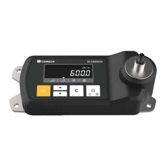
- Page 9 External View 5-1. Display and Oeration Keys Unit Display Memory counter/ upper limit display Torque display Lower limit display ▼ mark display Power/Data/Settings key Check key Memory counter advance key Clear key Memory counter return key ① Torque display The torque value is displayed. If the pass/fail judgment result is OK, it will be displayed in blue, if it is HI-NG or LO-NG, it will be displayed in red, and if pass/fail judgment is not performed, it will be displayed in white.
- Page 10 5-2. Power Source and Output 1. Power port USB Type-C 2. Data communication port USB Type-C 1. Power port Connect the included power USB cable and AC adapter (sold separately) to the USB port. 2. Data communication port Connect a USB cable (sold separately) for communication to the USB port. ...
- Page 11 "When a torque load is applied, the displayed torque increases, and when the load is released the displayed torque returns to 0. ▼ mark above RUN on the front panel is displayed. This is mainly used when calibrating the DLC-G main unit."...
- Page 12 ● Statistical processing function (number of samples, maximum value, minimum value, average value) ① Use the keys to display the final memory counter value for the range you want to process statistically. ② Press the key once to display “dAtA”. ③...
- Page 13 ● Data output _ sequential output After measurement and after reading data with key, press key to output the data. Data is also output when the auto memory reset is activated. ● Data output _ bulk output ① When the final memory counter value of the output range is displayed and the key is pressed, "dAtA"...
- Page 14 *For information on how to switch the auto power off, please refer to "7-2. Parameter Settings." ● Error display message The DLC-G has a self-diagnosis function that displays error messages Err1-9 when a malfunction occurs. For a list of error messages, please refer to "Chapter 11. Error Message List."...
- Page 15 Various Settings This section explains the functions and operation methods of each setting. For information on how to set up via communication from an external device, please refer to "9-3. Setting up from an external device." 7-1. Setting Items Top left Main display Item Default...
- Page 16 7-2. Parameter Settings ● Read the setting screen When no load is applied, pressing the key will take you to the item selection screen. ● Setting item selection "Select data processing ""dAtA"" or parameter setting ""SEt"". * ""SEt"" is displayed in RUN mode." •...
- Page 17 ● Unit setting (factory setting: cN・m) Set the units. • Use the keys to select "cN m" / "kgf cm" / "ozf in" / "lbf in". • Press the key to set and proceed to the next step. • Pressing the key will proceed to the next step without setting.
- Page 18 ● Auto power off setting (factory setting: 10 minutes) Sets the auto poeer off time. • Use the keys to select 10 minutes ("10"), 30 minutes ("30"), 60 minutes ("60"), or none ("nonE"). • Press the key to set and proceed to the next step. •...
- Page 19 ● Parity setting (factory setting default: none) Sets the communication parity. • Use the keys to select none (nonE), even (EvEn), or odd (odd). • Press the key to set and proceed to the next step. • Press the key to proceed to the next step without setting. •...
- Page 20 ③ Connect the included USB power cable to the USB power port on the side of the DLC-G main unit, and connect the AC adapter (sold separately) to an outlet. (Leave the unit for at least 30 minutes after turning on the power.) ④...
- Page 21 8-2. Measurement Object Installation The measurement operation is explained with reference to the following setting example. Measurement mode setting PEAK mode Upper limit setting 100.0 cN m Lower limit setting 50.0 cN m Auto memory reset settin 0.5 seconds ① With no load, perform auto zero adjustment with the key.
- Page 22 9-1. USB Output • Connect the DLC-G to an external device with a communication cable (catalog No. 586 or No. 587). • Set the communication settings to match those of the external device. (For setting instructions, refer to "Chapter 7: Various Settings.")
- Page 23 *2 Judgment result: "O K" for OK, "H I" for HI-NG, "L O" for LO-NG, "- -" if no judgment is made. *3 Fixed value: Fixed value due to compatibility format with other products. When dF-3 is set (Tohnichi standard format) 9 10 11 12 13 14 15 16 17 18 19 20...
- Page 24 9-3. Setting from an External Equipment You can change the settings of the DLC-G by inputting commands from an external device. When changing settings via command communication, be sure to do so with no torque load. When sending two or more settings in succession, wait at least 200 ms after receiving a response before sending the next command.
- Page 25 Operation key is continuously properly. Err1 - 5 pushed. If Err does not disappear, it needs to be repaired. Please contact TOHNICHI or your nearest distributor. It needs to be repaired. Please contact Err8 CPU / Memory error TOHNICHI or your nearest distributor.
- Page 26 ■Tohnichi Asia Technical Support Office (TATSO) TEL.+66 33 002307 FAX.+66 33 002337 271/184 Moo 6, Tambon Borwin, Amphur Sriracha, Chonburi, 20230 Thailand E-mail: tatso@tohnichi.com ● All rights reserved. No reproduction or republication without written permission. ● ©Tohnichi Mfg. Co., Ltd. All Rights Reserved. 08.24.EN...
Need help?
Do you have a question about the DLC-G and is the answer not in the manual?
Questions and answers