
Related Manuals for emmeti Console Manager


Summary of Contents for emmeti Console Manager
- Page 1 Console Manager Supervisore per max 16 unità terminali Manuale installazione ed uso | Edizione IT01...
- Page 2 AVVERTENZE GENERALI ......... 4 GENERAL WARNING ..........38 DESCRIZIONE ..............6 DESCRIPTION ..............40 2. CARATTERISTICHE TECNICHE ......7 2. TECHNICAL FEATURES ..........41 INSTALLAZIONE ............8 INSTALLATION..............42 4.1 Collegamenti .............. 8 3.1 Connections ............42 INTERFACCIA UTENTE ..........6 USER INTERFACE ............
- Page 3 Avvertenze Generali Il prodotto non è destinato ad essere usato da persone (bambini compresi) le cui capacità fisiche, sensoriali o mentali siano ridotte, oppure con mancanza di esperienza o di conoscenza, a meno che esse abbiano potuto beneficiare, attraverso l’intermediazione di una persona responsabile della loro sicurezza, di una sorveglianza o di istruzioni riguardanti l’uso del prodotto.
- Page 4 Non effettuare nessun tipo di intervento o manutenzione, non rimuovere nessun elemento di protezione senza aver prima scollegato la scheda dall’alimentazione elettrica. Effettuare i collegamenti elettrici secondo le leggi e le norme nazionali vigenti. Non torcere, staccare o tirare i cavi elettrici che fuoriescono dalla scheda anche se non è...
- Page 5 DESCRIZIONE Il supervisore remoto permette di comandare fino a 16 unità terminali (ventilconvettori, cassette idroniche, apparecchi canalizzabili) per il condizionamento di ambienti ad uso domestico, residenziale e pubblico. Il supervisore è costituito da una scheda elettronica alloggiata nel suo contenitore plastico ed è progettata per l’installazione remota a parete; la connessione alla scheda a bordo del terminale idronico avviene attraverso un cavo a doppio isolamento a 3 conduttori per lo scambio d’informazioni della rete RS-485 “Console Bus”.
- Page 6 CARATTERISTICHE TECNICHE Fig. 1 Tensione alimentazione 230 AC [V] +10%/-15% Frequenza alimentazione 50/60 Hz Potenza assorbita 1.6 [W] Grado di protezione IP 30 dopo installazione Temperatura di funzionamento Umidità di funzionamento 10÷90 [%] (senza condensa) Temperatura di stoccaggio -10/+60 [°C] Grado di inquinamento Pollution degree (II) Tensione impulsiva nominale...
- Page 7 INSTALLAZIONE L’installazione ed il collegamento elettrico del dispositivo devono essere eseguiti da personale qualificato ed in conformità alle leggi vigenti del paese in cui viene effet- tuata l’installazione. Utilizzare le costanti di correzione della temperatura ambiente (P24 e P25) per la taratura della console in fase di installazione.
- Page 8 SUPERVISOR BMS SUPERVISOR BUS L1 L1+ + L1 L1- - GN GND D L1 L1+ + L1 L1- - Linea di alimentazione 230V AC GN GND D Powe e r r su sup p p p l l y y 230 230V V A A C C Linea di alimentazione 230V AC Cavo consigliato: 2x0.75 isolato in PVC...
- Page 9 Cavo in uscita da una cassetta di derivazione Effettuare i collegamenti elettrici, rispettando la polarità e le connessioni come da Fig. 4. Fissare la plastica posteriore alla cassetta di derivazione. Installare Il supervisore fissando la plastica anteriore ad incastro. Fig. 4...
- Page 10 Cavo in uscita da un foro nel muro Fissare il fondo alla parete. Effettuare i collegamenti elettrici, rispettando la polarità e le connessioni come da Fig. 5 Fissare la plastica posteriore al fondo Installare Il supervisore fissando la plastica anteriore ad incastro.
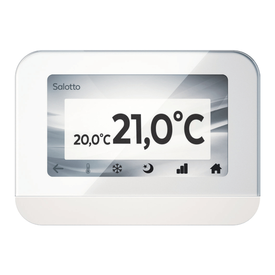
- Page 11 INTERFACCIA UTENTE 4.1 Primo avvio, configurazione del sistema Al primo avvio del sistema è necessario effettuare la configurazione e la ricerca delle zone dell’impianto. Vedere Par. 6.8 Ricerca Zone. L’impostazione di fabbrica della lingua è l’inglese. Per modificare l’impostazione vedere il Par.
- Page 12 Icone Descrizione Menu Impostazioni generali Funzione broadcast Programmazione settimanale Visualizzazione avvisi e allarmi 4.3. Gestione Zone Selezionando una zona, si entra nella schermata di controllo del singolo ventilconvettore. Selezionare per tornare alla schermata precedente.
- Page 13 Icons Descrizione Impostazione temperatura ambiente (setpoint) Selezione modalità di funzionamento Selezione stato di funzionamento Selezione velocità ventilatore Temperatura ambiente impostata (Set-point) Temperatura ambiente rilevata Lista Parametri e Stati I/O Schermata Home Zone Ritorno alla schermata precedente...
- Page 14 Icone di stato Descrizione Modalità riscaldamento: Il ventilconvettore opera nella logica della stagione invernale. Modalità raffreddamento: Il ventilconvettore opera nella logica della stagione estiva. Modalità ventilazione: Il ventilconvettore opera in sola ventilazione. OFF: il ventilconvettore è spento Economy: Il ventilconvettore opera nella logica di risparmio energetico. In raffreddamento la temperatura impostata viene incrementato e in riscaldamento decrementato del valore scelto (default 6°C).
- Page 15 FUNZIONI 5.1 Impostazione temperatura ambiente (setpoint) 1. Premere 2. Premere > per aumentare o < per diminuire la temperatura richiesta. Il passo di regolazione è di 0,5° C. Convalidare con . 5.2 Modo di funzionamento Selezionare l’icona corrispondente per ottenere il modo desiderato: Raffreddamento, Riscaldamento, Ventilazione.
- Page 16 5.3 Accensione, spegnimento, economy Selezionare l’icona corrispondente per ottenere lo stato del ventilconvettore desiderato: spento, risparmio energetico o acceso. Convalidare con 5.4 Selezione velocità ventilatore Selezionare una delle icone per ottenere la velocità del ventilatore desiderata: minima, media, massima o automatica.
- Page 17 5.5 Programmazione settimanale (Valido per tutte le zone) Ferie Premere . Si possono impostare fino a 8 programmi suddivisi in due pagine. Premere per creare o modificare un programma. per attivare o disattivare un programma. Premere Inserire il nome del programma (es. Ferie) e premere Invio. N.B.: Per cancellare un programma è...
- Page 18 per creare o modificare il programma del giorno scelto. Premere Per copiare il programma del giorno (anche se vuoto) in un altro giorno premere e selezionare i giorni scelti. Convalidare con Si possono programmare 8 fasce orarie per ogni giorno della settimana suddivise in due pagine. Premere per impostare o modificare il programma.
- Page 19 Impostare l’ora di inizio e la modalità desiderata utilizzando . Convalidare con Es. ore 8:00 inizio modalità COMFORT. Modalità: COMFORT (acceso) - OFF (spento) - ECO (risparmio energetico) - X (nessuna selezione). e selezionare X. Per cancellare una fascia oraria già impostata, premere 5.6 Funzione Broadcast Con la funzione Broadcast è...
- Page 20 5.7 Avvisi & Allarmi L’icona segnala la presenza di un avviso o un allarme. Per visualizzare l’allarme: 1. Premere oppure 2. Selezionare nel menu Impostazioni: Avvisi & Allarmi. 3. Identificare il codice utilizzando la tabella seguente. 4. Per cancellare gli avvisi selezionare ogni riga e premere Reset. Allarmi Codice Descrizione...
- Page 21 Avvisi Codice Descrizione Avviso TMIN: In riscaldamento, la temperatura dell’acqua in batteria non è abbastanza calda. Avviso TMAX: In raffreddamento, la temperatura dell’acqua in batteria non è abbastanza fredda. Avviso Antigelo: Funzione antigelo attiva. Errore di Connessione tra console e scheda a bordo macchina. Avviso filtro aria: Filtro dell’aria sporco, da pulire o sostituire.
- Page 22 5.8 Parametri e Stati I/O Selezionare per accedere al menu Configurazione. Per visualizzare la lista Parametri o Stati (in sola lettura) selezionare la voce corrispondente. Per modificare i parametri: 1. Spegnere il ventilconvettore (v. par. 5.3). 2. Premere sulla riga del parametro che si vuole modficare. 3.
- Page 23 DESC. VALORI U.M. DEFAULT 0=2 tubi 108 Tipologia Impianto 1=4 tubi 0=Manuale 1=Sonda acqua 2=Sonda aria P2 202 Cambio stagione 3=Centralizzato 4=solo estate 5=solo inverno 614 Banda proporzionale 10:100 °C/10 30,0°C 613 Banda neutra 10:100 °C/10 30,0°C 0=termostatata 1=Continua in estate P5 204 Ventilazione 2=Continua in inverno 3=Continua estate e inverno...
- Page 24 DESC. VALORI U.M. DEFAULT 0=disattivato 2=pressostato differenziale 3=forzatura STANDBY Configurazione 4=cambio stagione centralizzato P13 302 ingresso Multifuzione 5=allarme motore AC 6=forzatura ventilazione 7=Economy 8=sonda esterna Stato ingresso 0=Normalmente aperto P14 301 multifuzione 1=Normalmente chiuso T.min H2O P15 602 250:500 °C/10 Riscaldamento 36,0°C T.MAX H2O...
- Page 25 DESC. VALORI U.M. DEFAULT P27 519 MAX set point 100:400 °C/10 30,0°C P28 413 V min ventilatore DC 0:100 P29 414 V med ventilatore DC 0:100 P30 415 V max ventilatore DC 0:100 P31 106 Indirizzo LOCAL BUS 1:247 P32 105 Indirizzo MODBUS 1:247 P33 101 Reset di fabbrica Password DEFAULT 465...
- Page 26 MENU IMPOSTAZIONI 6.1 Accoppiamento App con il Supervisore Accoppiamento Per effettuare l’associazione dell’app con il supervisore: 1. Premere 2. Selezionare Accoppiamento. Nella schermata viene visualizzato il QR code che rappresenta l’ID del dispositivo. Per eseguire l’associazione seguire le indicazioni presenti nella app sullo smartphone.
- Page 27 Nella schermata successiva: 4. Impostare l’ora corretta utilizzando le frecce: . Convalidare con 5. Confermare tutte le modifiche con 6.3 Impostazione salvaschermo Per modificare il tempo di inattività dopo il quale entra in funzione il salvaschermo: 1. Premere 2. Selezionare Salvaschermo nel menu Impostazioni. 3.
- Page 28 6.4 Configurazione Wi-Fi Per connettere il supervisore alla rete Wi-Fi: Premere Selezionare Wi-Fi nel menu Impostazioni. Selezionare la rete Wi-Fi alla quale si vuole collegare il dispositivo. Digitare la password della rete. Confermare con Invio. 6.5 Impostazione lingua L’impostazione di fabbrica della lingua è l’inglese. Per modificare la lingua: 1.
- Page 29 6.6 Riavvio Console Per riavviare la console: 1. Premere 2. Selezionare Riavvio Console nel menu Impostazioni. 3. Convalidare con 6.7 Impostazione retroilluminazione Impostare la luminosità Per modificare la luminosità della retroilluminazione dello schermo: 1. Premere 2. Selezionare Retroilluminazione nel menu Impostazioni. 3.
- Page 30 6.8 Ricerca Zone (dopo aver assegnato indirizzi univoci alle zone) Per fare la Ricerca Zone: 1. Premere 2. Selezionare Ricerca Zone nel menu Impostazioni. Il supervisore automaticamente effettua la ricerca dei ventilconvettori collegati all’impianto. Terminata la ricerca viene visualizzata la lista dei ventilconvettori. Il nome dato di default è Adr seguito dall’indirizzo Modbus a 3 cifre (indirizzo variabile fino a 247).
- Page 31 6.9 Gestione Zone Per configurare le zone: 1. Premere 2. Premere Gestione Zone nel menu Impostazioni. 3. Premere sulla riga della zona che si vuole modificare. Inserire il nuovo nome e premere Invio per confermare. Premere per verificare le informazioni di una zona (indirizzo modbus, stato della connessione alla rete, eventuali allarmi e/o avvisi).
- Page 32 6.10 Impostazioni di fabbrica Per riportare il supervisore alle impostazioni di fabbrica (impianto vuoto): 1. Premere 2. Premere Impostazioni di fabbrica dal menu Impostazioni. 3. Inserire la password: omnibus360. Premere Invio. 6.11 Informazioni di sistema Per verificare il nome del produttore e la versione del firmware caricata: 1.
- Page 33 VERSIONE CON FONDO Fondo in plastica per installazione esterna alla parete. Fig. 6 MANUTENZIONE ORDINARIA Per pulire, utilizzare un panno asciutto. Eseguire la pulizia del display con panno specifico per pulizia lenti. Non pulire con prodotti aggressivi. Non bagnare il prodotto nel tentativo di pulirlo. Non immergere il prodotto in acqua.
- Page 34 SMALTIMENTO Le parti di consumo e quelle sostituite vanno smaltite nel rispetto della sicurezza e in conformità con le norme di protezione ambientale. A fine ciclo di vita l’apparecchiatura deve essere consegnata ad un centro di raccolta autorizzato a livello locale e/o regionale. A.
- Page 35 B. Informazioni sullo smaltimento per gli utenti commerciali 1. Nell’Unione Europea Se il prodotto è impiegato a scopi commerciali, procedere come segue per eliminarlo. Contattare il proprio rivenditore che fornirà informazioni circa il ritiro del prodotto. Potrebbero essere addebitate le spese di ritiro e riciclaggio. Prodotti piccoli (e quantitativi ridotti) potranno essere ritirati anche dai centri di raccolta locali.
- Page 36 Nome Descrizione Stati I/O Valore letto dalla sonda SE di temperatura della console [°C]. Valore letto dalla sonda AS di temperatura ambiente [°C]. Valore letto dalla sonda WS di temperatura dell'acqua [°C]. Valore letto dalla sonda CS di temperatura di mandata [°C]. Valore letto dalla sonda di temperatura dell’ingresso multifunzione [°C].
- Page 37 General warning The product cannot be used by people (including children) with reduced physical, mental or sensory capabilities or inexperienced persons unless they received, through a delegated responsible person, surveillance or a training or proper instruction about the product. Each operation for installation and/or maintenance on OMNIBUS 360 controllers must be executed by qualified personnel only.
- Page 38 Before proceeding with any installation and/or maintenance operation or before removing any protection device, make sure that the electronic board has been disconnected from the power supply. Electrical connections must respect the safety norms and rules of the Country where the product is installed. Do not twist, remove or pull the electrical cables connected to the electronic board, even if it is not connected to the power supply.
- Page 39 DESCRIPTION The remote Supervisor of is designed for controlling up to 16 water terminal units (fan coil units, cassettes, high pressure ducted units) for air conditioning and heating applications in domestic, residential or public buildings. It is designed for wall installation and it is composed by an electronic board located in a plastic casing and a 4.3”...
- Page 40 TECHNICAL FEATURES Fig. 1 Power supply 230 AC [V] +10%/-15% Power frequency 50/60 Hz Absorbed power 1.6 [W] Protection grade IP 30 after installation Operating temperature Operating humidity 10÷90 [%] (without condensate) Storage temperature -10/+60 [°C] Pollution degree Pollution degree (II) Nominal impulse voltage 2500V Ball pressure test temperature...
- Page 41 INSTALLATION The installation and electrical connection of the device must be carried out by qualified personnel and in compliance with the laws in force in the country where the installation is carried out. For a correct calibration of the console, it is necessary to set the constant correction values of the room temperature (P24 and P25).
- Page 42 SUPERVISOR BMS SUPERVISOR BUS L1 L1+ + L1 L1- - GN GND D L1 L1+ + L1 L1- - Power supply 230V AC GN GND D Powe e r r su sup p p p l l y y 230 230V V A A C C Power supply 230V AC Recommended cable: 2x0.75 insulated PVC...
- Page 43 Cables coming from a junction box in the wall Make the electrical connections by respecting polarity and connection as shown in Fig. 3. Fix the back plastic to the junction box. Install the console by fixing the front plastic : make a little pressure to interlock it. Fig.
- Page 44 Cables coming from a junction box in the wall (on-wall version) Fix the plastic bottom panel to the wall. Make the electrical connections by respecting polarity and connection as shown in Fig. 5. Fix the back plastic to the bottom panel Install the console by fixing the front plastic : make a little pressure to interlock it.
- Page 45 USER INTERFACE 4.1 First start, system configuration At the first start-up of the system, it is necessary to configure and search for the system zones. See Par. 6.8 Zone Search. English is the default language. To change the language see Par. 6.5 Language setting. 4.2 Main menu and Home Zone Living room Kitchen...
- Page 46 Icons Descriptions General settings Broadcast function Weekly program Alarms and warnings visualization 4.3. Zone management Living room By selecting a zone, you enter the control screen of the single fan coil. Select to return to the previous screen.
- Page 47 Icons Description Room temperature setting Operating mode setting On, Off, Economy setting Fan speed selection Room temperature set point Detected room temperature Parameters and I/O Status lists Home Zone screen Return to the previous screen...
- Page 48 Status icons Description Heating mode: the fan coil operates in Winter mode. Cooling mode: the fan coil operates in Summer mode. Fan mode: the fan coil operates in ventilation mode only. OFF: the fan coil is turned off. Economy mode: energy saving by shifting the setpoint. In cooling mode the set point is increased and in heating it is decreased by the set value (default 6 °...
- Page 49 FUNCTIONS 5.1 Room temperature setting Set the temperature 1. Tap 2. Tap > to increase or < to decrease the desired temperature. The regulation step is 0,5° C. 3. Confirm with . 5.2 Operating mode Operating mode Select the desired operating mode icon: Cooling, Heating, Fan.
- Page 50 5.3 On, Off, economy Status Select the desired fan coil status icon. Confirm with 5.4 Fan speed selection Fan speed Select the desired fan speed icon: min, med, max or automatic. Confirm with In AUTO mode, the fan speed changes according to the difference between setpoint temperature and room temperature (the highest is the temperature difference, the highest is the fan speed).
- Page 51 5.5 Weekly program Programs Holidays . It is possible to set up to 8 programs divided in two pages. to create or change a program. to activate or deactivate a program. Program name Write the name of the program (ex. Holidays) and tap Invio. N.B.: To delete a program it is enough to cancel the name in this screen.
- Page 52 Program: Holidays Monday Friday Tuesday Saturday Wednesday Friday Thursday to create or change the program of the day. To copy the program of the day (even if it is empty) to another day, tap and select the chosen days. Confirm with Change day: Monday It is possible to program up to 8 time slots for each day of the week, divided into two pages.
- Page 53 Set time and event mode Set the start time and the desired event mode using . Confirm with Ex. 8:00 AM COMFORT mode starts. Mode: COMFORT (on) - OFF - ECO (energy saving) - X (no selection). and select X. To delete an already set time slot, tap 5.6 Broadcast function Apply to all zones...
- Page 54 5.7 Warnings & Alarms The icon indicates the presence of a warning or alarm. To visualize the type of alarm: 1. Tap 2. Select in the Information menu: Warnings & Alarms. 3. Identify the code using the following table. 4. To delete the warning select each row and tap Reset. Alarms Code Description...
- Page 55 Warnings Code Description TMIN warning: water temperature in heating mode is not warm enough. TMAX warning: water temperature in cooling mode is not cold enough. Anti-frost warning: air temperature is too low, anti-frost function active (heating valve activated). Connection warning: wrong connection between remote console and card on the unit.
- Page 56 5.8 Parameters and I/O Status Select to get access to the Configuration menu. Configuration Parameters I/O Status To visualize the Parameters or I/O Status (read only) select the corresponding entry. Parameters Name Value To change the parameters: 1. Turn off the fan coil (see par. 5.3). 2.
- Page 57 DESC. VALUES U.M. DEFAULT 0=2 pipes 108 Plant type 1=4 pipes 0=Manual 1=Water probe 2=Air probe P2 202 Change of season 3=Centralised 4=Summer only 5=Winter only 614 Proportional band 10:100 °C/10 30,0°C 613 Neutral band 10:100 °C/10 30,0°C 0=Thermostat 1=Continue in summer P5 204 Ventilation 2=Continue in winter 3=Continue summer &...
- Page 58 DESC. VALUES U.M. DEFAULT 0=deactivated 2=differential pressure switch 3=STANDBY force Multi-fuction input 4=Centralised season change P13 302 configuration 5=Ac motor alarm 6=ventilation force 7=Economy 8=external probe Multi-fuction input 0=normally open P14 301 status 1=normally closed T.min H2O Heating P15 602 250:500 °C/10 36,0°C...
- Page 59 DESC. VALUES U.M. DEFAULT P27 519 MAX set point 100:400 °C/10 30,0°C P28 413 V min fan DC 0:100 P29 414 V med fan DC 0:100 P30 415 V max. fan DC 0:100 P31 106 LOCAL BUS address 1:247 P32 105 MODBUS address 1:247 P33 101 Factory Reset Password DEFAULT 465...
- Page 60 GENERAL SETTING 6.1 Pairing the App to the Supervisor In order to pair the app to the supervisor: 1. Tap 2. Select Pairing. The screen displays the QR code representing the device ID. To perform the pairing, follow the instructions in the app on the smartphone. Select RESET to reset the password (KEY) and regenerate the QR code.
- Page 61 Hour setting On the following screen: 4. Set the correct hour by using: . Confirm with 5. Confirm all settings with 6.3 Screensaver setting Screensaver Select the idle time Date No image Hour To change the idle time after which the screensaver is activated: 1.
- Page 62 6.4 Wi-Fi Configuration Wi-Fi Status To connect the supervisor to a Wi-Fi network: 1. Tap 2. Selet Wi-Fi in the Information menu. 3.Select the Wi-Fi network to which you want to connect the device. 4.Type the network password and press Invio. 6.5 Language setting Language English is the default language.
- Page 63 6.6 Restarting the Console Restarting Console Reboot To restart the console: 1. Tap 2. Select Restarting Console in the Information menu. 3. Confirm with 6.7 Backlight setting Backlight setting To change the brightness of the screen backlight: 1. Tap 2. Select Brightness in the Information menu. 3.
- Page 64 6.8 Zone Search Network scan Scan in progress, wait... To do the Zone search: 1. Tap 2. Select Zone search in the Information menu. The supervisor automatically searches for fan coils connected to the system. Network Once the search is complete, the list of fan coils is displayed. The default name given is Adr followed by the 3-digit Modbus address (variable address up to 247).
- Page 65 6.9 Zone Management Zone configuration To configure the zone: 1. Tap 2. Select Zone management in the Information menu. 3. Tap on the line of the zone you want to modify. Enter the new name and select Invio to confirm. Zone information name: kitchen address: 1...
- Page 66 6.10 Factory settings Enter the password reset To restore the supervisor to factory settings (empty system): 1. Tap 2. Select Factory settings in the Information menu. 3. Enter the password: omnibus360. Select Invio. 6.11 System information TTo check the manufacturer name and the firmware version loaded: 1.
- Page 67 ON-WALL VERSION Plastic bottom panel for installation on the wall. Fig. 6 ORDINARY MAINTENANCE To clean, use a dry cloth. Clean the display with a special lens cleaning cloth. Do not clean with aggressive products. Do not wet the product in an attempt to clean it. Do not immerse in water.
- Page 68 DISPOSAL Consumable parts and replaced components must be dismissed in accordance to the safety norms and environmental protection standards. At the end of its service life the unit must be delivered to an authorised recycling centre. A. Information on Disposal for Users (private households) 1.
- Page 69 B. Information on Disposal for Business Users 1. In the European Union If the product is used for business purposes and you want to discard it, please contact your dealer who will inform you about the take-back and possible related costs. Small products (and small amounts) might be taken back by your local collection facilities.
- Page 70 ALLEGATO/ENCLOSURE Fig. 7 Connection Local Bus...
- Page 71 BMS Network Features Protocol RS 485 Type Modbus RTU Speed 9600 bit/s Data Bit Parity Stop bit...
- Page 72 A Purmo Group Brand Ogni cura è stata posta nella creazione di questo documento. Nessuna parte di questo documento può essere riprodotta o diffusa senza l’espresso consenso scritto di Emmeti S.p.A Unipersonale. I dati contenuti in questa pubblicazione possono, per una riscontrata esigenza tecnica e/o commerciale,subire delle modifiche in qualsiasi momento e senza preavviso alcuno.Pertanto Emmeti S.p.A.
Need help?
Do you have a question about the Console Manager and is the answer not in the manual?
Questions and answers