
Subscribe to Our Youtube Channel
Related Manuals for emmeti Console LCD 2.0


Summary of Contents for emmeti Console LCD 2.0
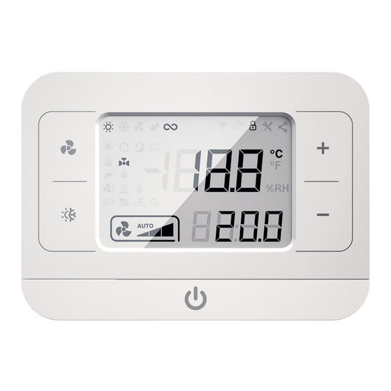
- Page 1 Console LCD 2.0 Controllore per sistema Power IdroLAN 2.0 Manuale installazione ed uso | Edizione IT01...
-
Page 2: Table Of Contents
AVVERTENZE GENERALI ......... 4 GENERAL WARNING ......... 26 1. DESCRIZIONE ............6 1. DESCRIPTION ............28 2. INTERFACCIA UTENTE ........6 2. USER INTERFACE ..........28 3. FUNZIONI ..............10 3. FUNCTIONS .............. 32 3.1 Service Tool ............ 12 3.1 Service Tool ............ 34 4. -
Page 4: Avvertenze Generali
Avvertenze Generali Il prodotto non è destinato ad essere usato da persone (bambini compresi) le cui capacità fisiche, sensoriali o mentali siano ridotte, oppure con mancanza di esperienza o di conoscenza, a meno che esse abbiano potuto beneficiare, attraverso l’intermediazione di una persona responsabile della loro sicurezza, di una sorveglianza o di istruzioni riguardanti l’uso del prodotto. - Page 5 Non effettuare nessun tipo di intervento o manutenzione, non rimuovere nessun elemento di protezione senza aver prima scollegato la scheda dall’alimentazione elettrica. Effettuare i collegamenti elettrici secondo le leggi e le norme nazionali vigenti. Occorre sempre effettuare la messa a terra dell’unità.
-
Page 6: Descrizione
DESCRIZIONE La console remota permette di comandare le unità terminali ventilconvettori, cassette idroniche, apparecchi canalizzabili per il condizionamento di ambienti ad uso domestico, residenziale e pubblico. La console è costituita essenzialmente da una scheda elettronica alloggiata nel suo contenitore plastico, ed è progettata per l’installazione remota a parete; la connessione alla scheda a bordo del terminale idronico avviene attraverso un cablaggio composto da 4 fili per l’alimentazione elettrica e lo scambio d’informazioni. - Page 7 Comandi Descrizione Pulsante velocità ventilatore Pulsante modalità funzionamento (Raffreddamento/Riscaldamento) Pulsante regolazione temperatura ambiente Pulsante regolazione temperatura ambiente Pulsante On/Off Icone di stato Descrizione Temperatura ambiente: visualizzazione costante della temperatura ambiente e relativa unità di misura (gradi Celsius o Fahrenheit impostabili con DIP switch). Setpoint: visualizzazione del setpoint di temperatura ambiente impostato.
- Page 8 Icone di stato Descrizione Modalità riscaldamento: il regolatore opera nella logica della stagione invernale. Modalità raffreddamento: il regolatore opera nella logica della stagione estiva. Modalità neutra: intervallo di temperature nel quale il regolatore non è né in modalità invernale né in modalità estiva. Modalità...
- Page 9 Allarmi e avvisi Descrizione Warning connessione console: non c’è comunicazione tra console e scheda. Warning Finestra aperta: con finestra aperta, le uscite del regolatore sono disattivate. Warning Pompa Condensa: l’acqua in bacinella ha raggiunto un livello troppo alto. Warning WS Sensore temperatura acqua in batteria: l’acqua non è...
-
Page 10: Funzioni
FUNZIONI Accensione e spegnimento Per attivare il termoregolatore premere il tasto fino alla visualizzazione della schermata principale. Per disattivare il termoregolatore premere il tasto fino alla visualizzazione della scritta “OFF”. In caso di riattivazione dopo black out o caduta di tensione il sistema ritorna allo stato in cui si trovava nei 3 min precedenti all’evento. - Page 11 Allarmi Codice Descrizione Allarme no AS: Sonda temperatura ambiente non rilevata o valore di temperatura non valido. Allarme no WS: Sonda temperatura acqua non rilevata o valore di temperatura non valido. Allarme no CS: Sonda Check sensor di temperatura aria in mandata (o temperatura acqua in impianto 4 tubi) non rilevata o valore di temperatura non valido.
-
Page 12: Blocco Tasti
Blocco tasti Per bloccare i tasti premere contemporaneamente per 3 secondi i tasti verrà visualizzato sul display il simbolo del lucchetto. Per lo sblocco dei tasti ripetere la stessa procedura. Per attivare la funzione blocco utente (lock client) impostare il parametro 42 su 1. In modalità lock client è... - Page 13 Nome Descrizione Valore letto dalla sonda SE di temperatura della console [°C]. Valore letto dalla sonda AS di temperatura ambiente [°C]. Valore letto dalla sonda WS di temperatura dell'acqua [°C]. Valore letto dalla sonda CS di temperatura di mandata [°C]. Valore letto dalla sonda di temperatura dell’ingresso multifunzione [°C].
- Page 14 Parametri Per accedere al menù premere contemporaneamente per 3 secondi i tasti con la console in Standby, per uscire premere il tasto per 3 secondi. Scegliere il parametro da modificare con i tasti e poi confermare con Selezionato il parametro, modificare il valore con i tasti , poi confermare con il tasto ;...
- Page 15 P10 705 Durata Destratificazione 0:60 Riduzione SET 20:150 °C/10 ambiente 6,0°C 0=Normalmente aperto P12 310 Contatto finestra 1=Normalmente chiuso 0=disattivato 2=pressostato differenziale 3=forzatura STANDBY Configurazione 4=cambio stagione centralizzato P13 302 ingresso Multifuzione 5=allarme motore AC 6=forzatura ventilazione 7=Economy 8=sonda esterna Stato ingresso 0=Normalmente aperto P14 301...
- Page 16 P25 513 Correzione estate -20:20 °C/10 0 P26 518 Min set point 70:300 °C/10 10,0°C P27 519 MAX set point 100:400 °C/10 30,0°C P28 413 V min ventilatore DC 0:100 P29 414 V med ventilatore DC 0:100 P30 415 V max ventilatore DC 0:100 P31 106 Indirizzo LOCAL BUS 1:247 P32 105 Indirizzo MODBUS...
-
Page 17: Dip Switch
DIP switch DIP switch Descrizione DSW 1 Libero Visualizzazione della temperatura ambiente e del setpoint DSW 2 in gradi Celsius (OFF) o Fahrenheit (ON). DSW 3 Attivazione (OFF) o disattivazione buzzer (ON). 4 ON 5 OFF Viene visualizzato solo il setpoint. 6 OFF 4 OFF 5 ON... -
Page 18: Installazione
INSTALLAZIONE L’installazione ed il collegamento elettrico del dispositivo devono essere eseguiti da personale qualificato ed in conformità alle leggi vigenti del paese in cui viene effet- tuata l’installazione. Utilizzare le costanti di correzione della temperatura ambiente (Parametri P24 e P25) per la taratura della console in fase di installazione. - Page 19 Console +12V +12V Scheda Fig. 2...
- Page 20 Cavo in uscita da una cassetta di derivazione Far passare i cavi attraverso l’apertura centrale o laterale della plastica posteriore della console. Fissare la plastica posteriore alla parete. Effettuare i collegamenti elettrici utilizzando il connettore a 4 poli fornito con la console, rispettando la polarità...
- Page 21 Cavo in uscita da un foro nel muro Fissare il fondo alla parete. Far passare i cavi attraverso l’apertura centrale o laterale della plastica posteriore della console. Fissare la plastica posteriore al fondo Effettuare i collegamenti elettrici utilizzando il connettore a 4 poli fornito con la console, rispettando la polarità...
-
Page 22: Caratteristiche Tecniche
CARATTERISTICHE TECNICHE Fig. 5 Tensione alimentazione 12[Vdc]. Potenza assorbita 0.192 [W]. Grado di protezione IP 30 dopo installazione. Condizioni di funzionamento 0÷50 [°C] - 10÷90 [%] (senza condensa). Temperatura di stoccaggio -10/+60 [°C]. Peso 70 [g]. -
Page 23: Versione Con Fondo
VERSIONE CON FONDO Fondo in plastica per installazione esterna alla parete. Fig. 6 MANUTENZIONE ORDINARIA Pulizia del termoregolatore Per pulire, utilizzare un panno asciutto. Pulire il display con un panno specifico per pulizia lenti. Non pulire con prodotti aggressivi. Non bagnare il prodotto nel tentativo di pulirlo. Non immergere il prodotto in acqua. -
Page 24: Smaltimento
SMALTIMENTO Le parti di consumo e quelle sostituite vanno smaltite nel rispetto della sicurezza e in conformità con le norme di protezione ambientale. A fine ciclo di vita l’apparecchiatura deve essere consegnata ad un centro di raccolta autorizzato a livello locale e/o regionale. A. -
Page 25: Dichiarazione Di Conformità
1. Nell’Unione Europea Se il prodotto è impiegato a scopi commerciali, procedere come segue per eliminarlo. Contattare il proprio rivenditore che fornirà informazioni circa il ritiro del prodotto. Potrebbero essere addebitate le spese di ritiro e riciclaggio. Prodotti piccoli (e quantitativi ridotti) potranno essere ritirati anche dai centri di raccolta locali. -
Page 26: General Warning
General warning The product cannot be used by people (including children) with reduced physical, mental or sensory capabilities or inexperienced persons unless they received, through a delegated responsible person, surveillance or a training or proper instruction about the product. Each operation for installation and/or maintenance on controllers must be executed by qualified personnel only. - Page 27 Before proceeding with any installation and/or maintenance operation or before removing any protection device, make sure that the electronic board has been disconnected from the power supply. Electrical connections must respect the safety norms and rules of the Country where the product is installed. Always ground the unit.
-
Page 28: Description
DESCRIPTION The remote Console is designed for controlling water terminal units fan coil units, cassettes, high pressure ducted units for air conditioning and heating applications in domestic, residential or public buildings. It is composed by an electronic board located in a plastic casing, LCD screen, touch buttons and one NTC integrated air sensor. - Page 29 Commands Description Fan speed button Summer/Winter button Setpoint setting button (up) Setpoint setting button (down) On/Off button Icons Description Room temperature: visualization of the room temperature (°Celsius or Fahrenheit by choice). Setpoint: visualization of the room temperature setpoint. Fan speed: visualization of the fan speed (low, med, high or automatic).
- Page 30 Status icons Description Heating mode: the controller operates in Winter mode. Cooling mode: the controller operates in Summer mode. Dead band zone: temperature interval in which the controller is not operating neither in Winter nor in Summer mode. Fan mode: the controller operates in ventilation mode only. Continuous fan mode: by reaching the setpoint, the ventilation proceeds at low speed.
- Page 31 Alarms and Warnings Description Warning missing connection: there is no communication between remote console and card. Warning Window open: by open window, all outputs of the controller are deactivated. Warning Condensate pump: condensing water in the drain pan reached a dangerous level. Warning WS water temperature sensor: water is not hot (in Winter) or cold (in Summer) enough.
-
Page 32: Functions
FUNCTIONS ON/OFF In order to activate the controller, press the button until the main mask appears on the screen. In order to turn OFF the controller, press the button until “OFF” appears on the screen. In the event of reactivation after a blackout or power failure, the system returns to the state it was in during the 3 min before the event. - Page 33 Alarms Code Description Alarm no AS: air temperature sensor not present or providing a not valid value. Alarm no WS: water temperature sensor not present or providing a not valid value. Alarm no CS: check sensor at the air outlet not present (or water temp.
-
Page 34: Lock Buttons
Lock buttons In order to lock the buttons press simultaneously for 3 seconds the buttons the padlock symbol appears on the display. To unlock the buttons, repeate the procedure. In order to activate the lock client function set the parameter 42 to 1. In lock client mode it is possible to switch the console ON or OFF, change the set point and the fan speed. - Page 35 Name Description Value read by the SE temperature sensor inside the console [°C]. Value read by the AS room temperature sensor [°C]. Value read by the WS water temperature sensor [°C]. Value read by the CS air outlet temperature sensor [°C]. Value read by the temperature sensor connected to the multipurpose terminals [°C].
- Page 36 Parameters To enter the Parameters menu, turn O FF the console and press simultaneously for 3 seconds the buttons ; to exit the menu pr ess the button for 3 seconds. Select the desired parameter with buttons and then con rm with Modify the value of the selected parameter with buttons , then con rm with Press button...
- Page 37 DESC. VALUES U.M. DEFAULT 0=deactivated 2=differential pressure switch 3=STANDBY force Multi-fuction input 4=Centralised season change P13 302 configuration 5=Ac motor alarm 6=ventilation force 7=Economy 8=external probe Multi-fuction input 0=normally open P14 301 status 1=normally closed T.min H2O Heating P15 602 250:500 °C/10 36,0°C...
- Page 38 DESC. VALUES U.M. DEFAULT P27 519 MAX set point 100:400 °C/10 30,0°C P28 413 V min fan DC 0:100 P29 414 V med fan DC 0:100 P30 415 V max. fan DC 0:100 P31 106 LOCAL BUS address 1:247 P32 105 MODBUS address 1:247 P33 101 Factory Reset Password DEFAULT 465...
- Page 39 DIP switch Combination Description DSW 1 Free Visualization of the room temperature and setpoint DSW 2 in Celsius (OFF) or Fahrenheit (ON). DSW 3 Activation (OFF) or deactivation (ON) of the buzzer. 4 ON 5 OFF It is visualized only the setpoint. 6 OFF 4 OFF 5 ON...
-
Page 40: Installation
INSTALLATION The installation and electrical connection of the device must be carried out by qualified personnel and in compliance with the laws in force in the country where the installation is carried out. For a correct calibration of the console, it is necessary to set the constant correction values of the room temperature (P24 and P25). - Page 41 Console +12V +12V card Fig. 2...
- Page 42 Cables coming from a junction box in the wall Insert the cables through the central back opening or the side slots of the back plastic of the console. Fix the back plastic to the wall. Make the electrical connections by using the 4-pole connector supplied with the console, by respecting polarity (Fig.
- Page 43 Cables coming from a junction box in the wall (on-wall version) Fix the plastic bottom panel to the wall. Insert the cables through the central back opening or the side slots of the back plastic of the console. Fix the back plastic to the bottom panel Make the electrical connections by using the 4-pole connector supplied with the console, by respecting polarity (Fig.
-
Page 44: Technical Features
TECHNICAL FEATURES Fig. 6 Power supply 12[Vdc]. Absorbed power 0.192 [W]. Protection grade IP 30 after installation. Operating conditions 0÷50 [°C] - 10÷90[%] (without condensation). Storage temperature -10/+60 [°C]. Weight 70 [g]. -
Page 45: On-Wall Version
ON-WALL VERSION Plastic bottom panel for installation on the wall. Fig. 7 ORDINARY MAINTENANCE Cleaning the product To clean, use a dry cloth. Clean the display with a special lens cleaning cloth. Do not clean with aggressive products. Do not wet the product in an attempt to clean it. Do not immerse in water. -
Page 46: Disposal
DISPOSAL Consumable parts and replaced components must be dismissed in accordance to the safety norms and environmental protection standards. At the end of its service life the unit must be delivered to an authorised recycling centre. A. Information on Disposal for Users (private households) 1. -
Page 47: Declaration Of Conformity
1. In the European Union If the product is used for business purposes and you want to discard it, please contact your dealer who will inform you about the take-back and possible related costs. Small products (and small amounts) might be taken back by your local collection facilities. 2. -
Page 48: Allegati
ALLEGATO/ENCLOSURE... - Page 52 A Purmo Group Brand Ogni cura è stata posta nella creazione di questo documento. Nessuna parte di questo documento può essere riprodotta o diffusa senza l’espresso consenso scritto di Emmeti S.p.A Unipersonale. I dati contenuti in questa pubblicazione possono, per una riscontrata esigenza tecnica e/o commerciale,subire delle modifiche in qualsiasi momento e senza preavviso alcuno.Pertanto Emmeti S.p.A.
Need help?
Do you have a question about the Console LCD 2.0 and is the answer not in the manual?
Questions and answers