Table of Contents
Advertisement
Quick Links
Advertisement
Table of Contents

Related Manuals for emmeti FEBOS-CRONO


Summary of Contents for emmeti FEBOS-CRONO
- Page 1 FEBOS - CRONO Basic / Wifi INSTALLATION AND USE MANUAL...
-
Page 2: Table Of Contents
® All rights reserved. No part of this pubblication may be reproduced or distributed without written permission from Emmeti. Warning! Keep these manuals in a dry place avoiding in this way to spoil them. -
Page 3: Presentation
HP and to report the main displays of Using the SMART-MT, in addition to the normal commands on the the SMART-MT. mode and operating status of the HP, all the parameters relating to FEBOS-CRONO user terminal Energy meter Circulator Condensing boiler... - Page 4 MIRAI SMI heat pump and the control of room comfort and the related flows and energy costs of the residence. This platform consists of the following field devices: Febos-Crono (BASIC/WiFi), Febos-Energy, Febos-Power and Febos-Relay and a Cloud dedicated to their management. FEBOS-Power...
- Page 5 FEBOS-CRONO WiFi / FEBOS-CRONO 360° connectivity. Tablet or PC This is what makes the Febos-Crono world truly complete, the plug in WiFi. The presence of the WiFi module allows performance and independence, making it suitable for any type of installation.
-
Page 6: Warnings And Technical Data
( termosifoni , climatizzatori, finestre) in una posizione significativa per il controllo The FEBOS-CRONO must be installed at a height of 1.5m from the floor in a dry place free of air currents, away from heat sources ( radi- del comfort ambientale come riportato di seguito. -
Page 7: Installation
3. INSTALLATION... - Page 8 3. INSTALLATION TABLE OF CONTENTS...
-
Page 9: Wall Mounting
3. INSTALLATION 3.3 Wall mounting The FEBOS-CRONO can be fixed to the wall in two modes: flush with the wall or on a recessed box. Unhook the Febos Crono from the support base Attach the support base to the wall by passing the connectors, previously connected to the electrical circuit. - Page 10 The following icon is used to indicate where the screen must be touched to execute the instruction (It will not appear on the Febos-Crono display). Within the screens there are editable values. These are recognizable because they are enclosed in a cell, pressing the cell will display the keyboard on which to type the value, press OK to edit.
-
Page 11: General Information
Press the icon to access the settings. · Guest access level , default without password. · , with password 2019. User access level · Service access level , with the password supplied during the Emmeti course. To change the access level press the icon... - Page 12 4. GENERAL INFORMATION 4.3.1 Language change 4.3.2 Change of theme as desired To change the background theme press the icon To change the language press the icon Below are some examples of Blue, Green, Grey and Red: Then choose the language you want.
- Page 13 Colour pump Date and Time Febos Crono Date and Time NOTE: If the Febos-Crono is connected to the Internet, the date and time are automatically updated. At the first power on, the date and time flash until they are updat-...
-
Page 14: Wifi Connection (Febos-Crono Wifi Model)
On this screen there is a QRCode, which can be scanned with your smartphone, which refers to the link from which you can download the user manual in pdf format. In addition, there is the software version of Febos-Crono and SMART-MT (Heat Pump). The Febos-Crono automatically searches all available networks, showing at the top the network to which it is connected. - Page 15 4. GENERAL INFORMATION NOTE: If the Febos-Crono is not connected, select the WiFi net- work from those available. Router address Then enter the password and press OK. VPN server address WiFi Mac Address Device number WiFi network name If the password has been entered correctly, the WiFi icon will turn Signal between Febos-Crono and router green and indicate the signal strength.
-
Page 16: First Start-Up
ATTENTION At the first power supply of the Febos-Crono it is necessary to wait a few minutes before the display turns on. In addition, a period of time of at least 1 hour is required before the temperature and humidity sensors are fully operational and properly measure room values. - Page 17 5.3.2 System with Febos-Crono Slave. ATTENTION: On the Febos-Crono Master it is possible to configure up to a max- There must be a unique match between the Modbus (Slave) imum of 9 Febos-Crono Slaves, assigning each of them a Modbus addresses assigned on the Master and the Modbus addresses address between 11 and 19.
- Page 18 5. FIRST START-UP 5.3.3 Centralized Slave 5.3.4 Independent Slave If Centralized Slave is selected, the consents from Thermostat and If Independent Slave is selected, the consents from Thermostat Humidistat, in addition to supplying power to the relay outputs and Humidistat supply power only to the outputs (24Vdc max 20mA), are sent to the Heat Pump, which then comes relay (24Vdc max 20mA).
- Page 19 Press the icon then d. Press the Recipe selector to set it. The operating parameters (C402÷C407) and the connection specifications to the PCB TERMI- NAL BLOCK will be loaded from the Febos-Crono database. b. Press Recipe uploaded Recipe on...
- Page 20 5. FIRST START-UP e. Press to unload to the f. Pressing on a parameter it is possible to modify its value manually. SMART-MT the Recipe parameters. Confirm with Ok 5.5 Setting inputs of the electrical powers For the correct measurement of electrical powers it is essential to associate to each power, the relative input.
- Page 21 5. FIRST START-UP c. Select the input used for each electrical power. NOTE: If an electrical power is not managed (e.g. photovoltaic not installed) press its icon (e.g. “ ") to deselect it. The column on the left shows the electrical powers that can be measured, while the top row shows the available inputs: Energy meter pulse counter Pliers...
-
Page 22: Checking The Hp Inputs And Outputs
5. FIRST START-UP 5.6 Checking the HP inputs and outputs b. Press the icon to access screen 4.2 a.Press the icon to access the Heat Pump Set screen. of the I/O Status. c. Verification of the PCB TERMINAL BLOCK inputs. R1 out Check if the values displayed on the screen correspond to the physical status of the inputs in the HP. - Page 23 5. FIRST START-UP TABLE OF CONTENTS d. Check the outputs of the PCB TERMINAL BLOCK. Press and for 5 min it will be possible to manually change the status of the outputs and check their physical status on the HP. R1 out T1 out T2 out...
-
Page 24: Guest Screens
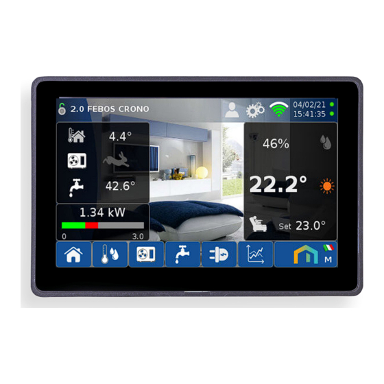
6.1 Screen 2.0 (Home) Pressing the icon accesses the read-only Home screen. On the right side is displayed the Room Widget, containing information relating to the room managed by Febos-Crono Relative humidity Humidistat consent Heating mode Cooling mode Thermostat consent... -
Page 25: Screen 2.1 Room Set
6. GUEST SCREENS 6.2 Screen 2.1 ROOM SET Pressing the icon accesses the screen 2.1 ROOM SET, which can be divided into three parts: 1) A read-only part, in which the Room Widget is re-proposed, where the dew temperature is added to the room temperature and relative humidity: Relative humidity Dew temperature... - Page 26 • in heating → Room temperature NOTE: < Room Temp Set - Room Temp Differential Thermostat consent involves switching of the respective relay on board the Febos-Crono. • in cooling → Room temperature > Room Temp Set + Room Temp Differential...
- Page 27 If a Modbus network (Master + Slave) has been configured, an additional screen is available on the Febos-Crono Master, the 2.2 ROOM SET, in which the operating status of all Febos-Crono Slaves is displayed. On screen 2.1, press the "...
-
Page 28: Screen 4.1 Heat Pump
6. GUEST SCREENS 6.3 Screen 4.1 HEAT PUMP 2) A read-only part, which displays the information related to the operation of the HP: Pressing the icon accesses the screen 4.1 HEAT PUMP, which can be divided into three parts. Water temperature for compressor Minimum water tempera- modulation 1) HP Widget, read-only, where information relative to the HP... - Page 29 6. GUEST SCREENS TABLE OF CONTENTS 6.3.1 Compressor modulation logic NOTE: The compressor starts only if the HP is and following a The maximum step reachable by the HP is still constrained by the active limitations (screen 4.3). call from the Thermostat ( ) Humidistat ( ) or If photovoltaic energy is available, and at the same time the water...
-
Page 30: Screen 5.1 Sanitary Hot Water
6. GUEST SCREENS 6.4 Screen 5.1 SANITARY HOT WATER 6.4.1 ACS programming ACS programming is based on two daily requests plus a mainte- Pressing the icon accesses screen 5.1 SANITARY HOT nance temperature. WATER, which can be divided into two parts: The logic implemented allows the HP to calculate how far in advance to give ACS consent, with the aim of reaching the set temperature, at the set time, to meet the two daily requests. -
Page 31: Screen 6.1 Electrical Powers
6. GUEST SCREENS TABLE OF CONTENTS 6.5 Screen 6.1 ELECTRICAL POWERS Pressing the icon accesses the screen 6.1 ELECTRICAL POWER, which can be divided into two parts: 1) The ELECTRICAL POWER Widget, which displays the flows of electricity between the Residence, Electricity network and Pho- tovoltaic (if available). -
Page 32: Graph Screens
6. GUEST SCREENS TABLE OF CONTENTS 6.6 GRAPH screens Pressing the icon accesses the graphs. Pressing “Hide” the icons relative to the Period that hide Screen 7.1 displays the GRAPH OF THE part of the graph are hidden. TEMPERATURES, daily or weekly: Graph Hides period Graph... - Page 33 6. GUEST SCREENS Absorbed electrical power ACS Electrical power consumption HP Electrical power consumption Socket Thermal power rendered in heating Thermal power rendered in cooling Screens 7.4 and 7.5 display the ENERGY GRAPHS, monthly or annual: Energy supplied to the grid Energy taken from the grid Energy produced by the photovoltaic Energy consumed by the residence...
-
Page 34: User Screens
On the 2.1 ROOM SET and 4.1 HEAT PUMP screens the icon access the alarm history is now visible 7.1.1 History of Febos-Crono alarms On the screen 2.1 ROOM SET, press the icon The following information is available on this screen:... -
Page 35: Heat Pump User Screens
7. USER SCREENS TABLE OF CONTENTS 7.2 Heat Pump User Screens 7.2.2 Screen 4.3 - Compressor limitations On screen 4.3 you can set compressor limitations to: On screen 4.1 HEAT PUMP the icon is now visible, as additional • Limit the noise of the HP at certain times, for example at night screens are available. -
Page 36: Electrical Power User Screen
7. USER SCREENS 7.2.4 Screen 4.5 – Cooling water temperature 7.3 Electrical Power User Screen On screen 4.5 it is possible to set the Target temperature of the On screen 6.1 ELECTRICAL POWERS the icon is now cooling water: visible, as an additional screen is available. Press on the cell to change its value Temperature The following settings are available on this screen:... - Page 37 8. INSTALLER SCREENS TABLE OF CONTENTS To view the screens reserved for the installer, recognizable by the 8.1.1 Screen - 1.13 FEBOS ENERGY DEBUG blue background, you must log in as Installer . 8.1 Screen - 1.12 DEBUG Press the icon then the icon I-TAE1/2: Current TA1/2 Sf-TAE1/2: TA1/2 offset...
-
Page 38: Installer Screens
8. INSTALLER SCREENS 8.2.1 - Room temp. differential 8.2.2 Booster Differential The Room temp differential applies to the Room Temperature The Booster Differential applies to the Room Temperature Set Set for the Thermostat call ( for calling the automatic Boost ( The consent shall be activated when: The logic of activating/deactivating the automatic Boost is com- •... - Page 39 (concrete, wood, plasterboard...) and other environmental conditions. 8.2.5 Window contact and Presence contact The Febos-Crono has available two digital inputs to be used as Window contact and Presence contact. Both inputs can be configured as: •...
-
Page 40: Heat Pump Screens - Service
8. INSTALLER SCREENS 8.3 HEAT PUMP screens - SERVICE Screen 4.6 defines the Climate curve in heating. In addition, the maximum temperature of the hot water at the radi- ant system is set (Par. C541) Carefully read the manual that accompanies the Heat Pump before changing the values of the following screens. - Page 41 8. INSTALLER SCREENS Screen 4.7 defines the climate curve in cooling. Cooling adjustment logic In addition, the minimum temperature of the cold water is set in the CASE 1 - Set 1 in normal operation. radiant system (Par. C542), to which is added the limitation on the = daily screed programming + Climate curve.
- Page 42 8. INSTALLER SCREENS 8.3.3 OFFSET 8.3.1 FROST PROTECTION For a correct calculation of the power output it is important that For the meaning of the values that can be set on the following the water temperature probes of the HP are aligned with each screen, refer to the manual that accompanies the HP.
-
Page 43: Sanitary Hot Water Screens - Service
8. INSTALLER SCREENS TABLE OF CONTENTS 8.4 SANITARY HOT WATER screens – SERVICE Carefully read the manual that accompanies the Heat Par. C704 Pump before changing the values of the following screens. Par. C705 Par. C706 Pressing the icon accesses the Sanitary Hot Water setting screen. - Page 44 Respect the environment! For a correct disposal, the different materials must be divided and collected according to the regulations in force. A. M. HVAC - Product Manual Writer Emmeti S.P.A. Unipersonale Via Brigata Osoppo, 166 +39 0 434 567 973 www.emmeti.com...
Need help?
Do you have a question about the FEBOS-CRONO and is the answer not in the manual?
Questions and answers
cosa vuole dire allarme fbc?