Advertisement
Available languages
Available languages
Quick Links
Advertisement

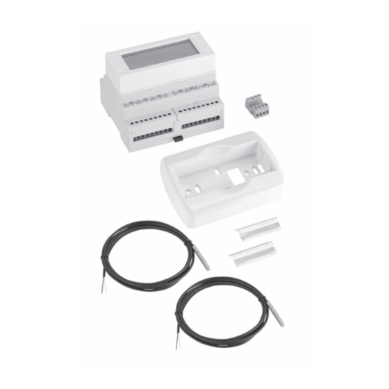
Related Manuals for emmeti RCE


Summary of Contents for emmeti RCE
- Page 1 MANUALE UTENTE USER MANUAL MANUEL D’INSTALLATION ET D’UTILISATION...
- Page 2 IT IT pag. 3 pag. 19 Vi ringraziamo per la fiducia concessaci nell’acquisto Thanks you very much for the confidence you have di questo prodotto. placed in us by purchasing our product. Vi invitiamo a leggere attentamente questo manuale We invite you to read this manual which shows the dove sono riportate le caratteristiche tecniche e tutte technical specifications and all relevant information le informazioni utili per ottenere un corretto funzion-...
- Page 3 IT IT INDICE 1. Introduzione......4 2. Funzionamento......5 2.1 Modalità di regolazione 2.1.1 Modalità ‘punto fisso’ 2.1.2 Modalità ‘modulante’ 2.1.3 Modalità ‘climatico’ 2.2. Richiesta TA 2.2.1 Riscaldamento 2.2.2 Funzione termostato di sicurezza 2.2.3 Raffrescamento 2.2.4 Funzione sicurezza condensa 2.3 Cambio stagione (selezione Estate/Inverno) 2.4 Accensione/spegnimento da remoto 3.
- Page 4 • Menu multilingua calcolata in funzione della temperatura esterna. • Gestione di una sola valvola miscelatrice con la possi- Il regolatore RCE è conforme alle direttive n° bilità di utilizzare o un servomotore modulante (0-10V) 2004/108/CE - n° 2006/95/CE e successive modi- oppure uno flottante (3 punti).
-
Page 5: Funzionamento
IT IT 2. FUNZIONAMENTO 2.1 - Modalità di regolazione miscelatrice, l’altra all’esterno tramite la relativa cus- todia per installazione sonda per esterno (opzionale). Il regolatore può effettuare tre tipologie di regolazi- Nel caso non sia presente un pozzetto per la sonda di oni selezionabili nell’apposito menu. - Page 6 IT IT 2. FUNZIONAMENTO • in modalità climatico la temperatura di manda- e chiude la valvola miscelatrice per evitare il surri- ta viene mantenuta costante al valore calcolato scaldamento dell'impianto. rispetto alla curva climatica. La curva climatica invernale viene calcolata in funzione della tem- 2.2.3 Raffrescamento peratura esterna rilevata ed ai punti impostati Dal momento in cui è...
- Page 7 (circolatore, misce- Estate/Inverno) latrice e generatore). Il regolatore per gruppi di miscelazione EMMETI è Esempio: di default sono impostati 3 step, pari a 2°C stato studiato per gestire il Riscaldamento ed il Raf- e di un'ora di durata ciascuno. Se durante il normale frescamento dell’impianto.
- Page 8 IT IT 2. FUNZIONAMENTO • “Da Comando Remoto”, dove il passaggio estate/ inverno e viceversa viene fatto tramite l’ingres- so digitale dedicato - Ingresso remoto stagione (contatto pulito), con la seguente logica Contatto Chiuso = Inverno, Contatto Aperto = Estate (questa logica può...
- Page 9 IT IT 3. INTERFACCIA 1 2 3 4 5 6 7 8 9 ¸ °C °F µ SET 1 2 3 4 5 OK Area di visualizzazione Area tasti Significato dei simboli sul display: 1 Campo informazioni: In questo campo viene visualizzato un testo, se questo è più lungo dei caratteri a disposizione il testo diventa scorrevole.
-
Page 10: Menù Utente
IT IT 4. MENÙ UTENTE 4.1 - Punto fisso Maschera principale: T i m p o s t a t °C Esempio di funzionamento invernale, temperatura rilevata dalla sonda di mandata di 25.0°C e la posIzione della miscelatrice tra il 40% e il 60%. •... - Page 11 IT IT 4. MENÙ UTENTE R I S C A L D A M E Con il simbolo radiatore nel campo visualizzazione Una volta selezionata la modalità dopo tre secondi viene mostrata la scritta: RISCALDAMENTO, pre- viene confermata la modifica e viene visualizzata la mendo nuovamente il tasto viene cambiata la stagio- maschera principale.
- Page 12 IT IT 4. MENÙ UTENTE 4.2 Modulante Maschera principale: T c a l c o l a t °C Esempio di funzionamento invernale, temperatura rilevata dalla sonda di mandata di 25.0°C, temperatura rilevata dalla sonda di ritorno di 22.0°C, temperatura impostata di 30.0°C, temperatura calcolata di 34.5°C e la posizione della miscelatrice tra il 40% e il 60%.
- Page 13 IT IT 4. MENÙ UTENTE R I S C A L D A M E Con il simbolo radiatore nel campo visualizzazione • Il tasto SET serve per accedere al menu avanzato viene mostrata la scritta - RISCALDAMENTO -, protetto da password. premendo nuovamente il tasto viene cambiata la sta- gione, quindi il simbolo del pulsante cambia in fiocco E' possibile visualizzare il valore di alcuni parametri,...
- Page 14 IT IT 4. MENÙ UTENTE 4.3 - Climatico Maschera principale: T c a l c o l a t °C Esempio di funzionamento invernale, temperatura rilevata dalla sonda di mandata di 25.0°C, temperatura rilevata dalla sonda esterna di -5.0°C, temperatura calcolata di 38.0°C e la posizione della miscelatrice tra il 40% e il 60%.
- Page 15 IT IT 4. MENÙ UTENTE R I S C A L D A M E • Il tasto SET serve per accedere al menu avanzato Con il simbolo radiatore nel campo visualizzazione protetto da password. viene mostrata la scritta - RISCALDAMENTO -, premendo nuovamente il tasto viene cambiata la sta- E’...
- Page 16 IT IT 5. ALLARMI In presenza di allarmi nel campo informazioni è mostrato con testo scorrevole il tipo di allarme in atto. Nel caso ci siano più allarmi verranno mostrati ciclicamente tutti gli allarmi. Nel campo valore è presente un numero che indica quanti allarmi sono attivi. Allarme Causa Effetto...
- Page 17 IT IT 5. ALLARMI Esempio: Sonda di mandata guasta A L L T M A N D Nel campo informazioni è visualizzato il testo scorrevole ‘ ALL T MANDATA FUORI SCALA’. Nel campo valore è visualizzato il valore 1 per indicare che è presente solo un allarme.
- Page 19 INDEX 1. Introduction......20 2. Operation........21 2.1 Regulation temperature 2.1.1 “Fixed temperature” mode 2.1.2 “Modulating” mode 2.13 “Climatic” mode 2.2 TA request 2.2.1 Heating 2.2.2 Safety thermostat function 2.2.3 Cooling 2.2.4 Condensation safety function 2.3 Changing Season (Summer / Winter selection) 2.4 Turning ON/OFF 3.
- Page 20 • Multilingual menu set as a function of the return temperature of the sys- tem. The RCE regulator complies with EEC directive no. - "Climatic" mode : allows to control of the climatic 2004/108 and ECC directive no. 2006/95 and sub.
-
Page 21: Operation
2. OPERATION 2.1 - Regulation mode it is possible to use the he sensor housing included in the kit by applying it on the flow collector. With The regulator can perform three types of settings this Regulation, the flow temperature is calculated that can be selected from the menu. - Page 22 2. OPERATION • in climatic mode, the flow temperature is kept 2.2.3 Cooling constant at a value calculated with respect to the From the moment the request is active for thermostat climatic curve. The winter temperature curve is TA after a delay the enabling is given to the heating/ calculated depending on the external temperature cooling source, the mixing valve and the pump.
- Page 23 1 - The system is not covered by the alarm after per- Winter selection) forming all the steps. The regulator for EMMETI mixing units was designed After performing all the steps of temperature rise to handle the Heating and Cooling of the system.
-
Page 24: Remote Power On/Off
2. OPERATION 2.4 - Remote Power on/off If during installation you have activated this function, it is possible to force the shut-down of the regula- tor with thermostat demand in place by a selector/ switch relating connected to the digital input - On/ Off remote input (volt free contact). - Page 25 3. INTERFACE 1 2 3 4 5 6 7 8 9 ¸ °C °F µ SET 1 2 3 4 5 OK Display area Keys area Meaning of symbols on the display: 1 Information field: This field displays a text, if it is longer than the available characters the text becomes sliding.
- Page 26 4. USER MENU The user has the ability to display the operating parameters and switch the regulator in heating and cooling. The information displayed varies depending on the mode set: 4.1 - Fixed temperature Main page: S E t T E M P E R °C Example of winter operation, temperature detected by the flow sensor is 25.0°C and the position of the mixing valve is between 40% and 60%.
- Page 27 4. USER MENU H E A T I N G With the radiator symbol in the display field the fol- • The SET button is used to access the advanced lowing writing is shown: HEATING by pressing the menu password protected. button again the season is changed, then the symbol of the button changes in snowflake and the wording will be displayed in the field COOLING.
- Page 28 4. USER MENU 4.2 - Modulating Main page: C A L C U L A T E D °C Example of winter operation, the temperature detected by the flow sensor of 25.0 °C, the temperature de- tected by the return sensor of 22.0 °C, set temperature of 30.0°C, the calculated temperature of 34.5 °C and the position of the mixing valve between 40% and 60%.
- Page 29 4. USER MENU H E A T I N G The radiator symbol in the display field shows the It is possible to display the value of certain param- message - HEATING - By pressing the button again eters, to do this press at any point of the display: the season is changed, then the symbol of the but- ton changes in snowflake and the wording will be displayed in the field - COOLING -.
- Page 30 4. USER MENU 4.3 - Climatic Main page: c a l c u l a t E D °C Example of winter operation, the temperature detected by the flow sensor of 25.0°C, the temperature de- tected by the external sensor of -5.0°C, the calculated temperature of 38.0°C and the position of the mixing valve between 40% and 60%.
- Page 31 4. USER MENU H E A T I N G • The SET button is used to access the advanced The radiator symbol in the display field shows the menu password protected. message - HEATING - By pressing the button again It is possible to display the value of certain param- the season is changed, then the symbol of the but- eters, to do this press at any point of the display:...
- Page 32 5. ALARMS In the presence of alarms in the information field is shown the scrolling text on the type of alarm in place. In case there are more alarms they will be shown all cyclically. In the value field is a number indicating how many alarms are active. Alarm Case Effect...
- Page 33 5. ALARMS Example: Flow sensor faulty F L O W T E M P In the field of information displays the scrolling text "FLOW TEMPERATURE ALARM’." In the value field is displayed the value 1 to indicate that only 1 alarm is present.
- Page 34 Note...
- Page 35 Note...
- Page 36 For proper disposal the different materials must be separated and transferred to authorized landfills according to the current regulations. EMMETI Spa Via B. Osoppo, 166 - 33074 Fontanafredda frazione Vigonovo (PN) Italy Phone 0434-567911 - Fax 0434-567901 Internet: http://www.emmeti.com - E-mail: info@emmeti.com...
Need help?
Do you have a question about the RCE and is the answer not in the manual?
Questions and answers