
Subscribe to Our Youtube Channel
Related Manuals for emmeti POWER idroLAN


Summary of Contents for emmeti POWER idroLAN
- Page 1 POWER idroLAN MANUALE INSTALLAZIONE ED USO MANUALE INSTALLAZIONE ED USO INSTALLATION AND USE MANUAL INSTALLATION AND USE MANUAL...
- Page 2 Vi ringraziamo per la fiducia concessaci Thanks you for the trust you have shown by nell’acquisto di questo prodotto. purchasing this product. Vi invitiamo a leggere attentamente questo Carefully read this manual which contains manuale dove sono riportate le caratteristi- the specifications and all the information che tecniche e tutte le informazioni utili per useful for the correct functioning.
- Page 3 VH and VC outputs “hot and cold valve” 2. CONNESSIONI ELETTRICHE 9.8 Uscite analogiche Hot e cold “valvole modulanti ” 2.1 Scheda Power IdroLAN / Card Power IdroLAN Hot and cold analog outputs “modulating valves” 9.9 Antibloccaggio valvole / Anti-locking of valves 3.
- Page 4 1. DESCRIZIONE / DESCRIPTION IT IT I ventilconvettori descritti in questo manua- The fan described in this manual comply with le sono conformi a quanto prescritto dalle the provisions of the following: seguenti Direttive: - DIRECTIVE 2014/35 / EU OF THE EUROPEAN - DIRETTIVA 2014/35/EU DEL PARLAMENTO PARLIAMENT AND OF THE COUNCIL of 26 EUROPEO E DEL CONSIGLIO del 26 febbra-...
- Page 5 They are not permitted applications of the Non sono ammesse applicazioni del ter- controller and related IDROLAN console moregolatore IDROLAN e relative console on not EMMETI unit. su unità non EMMETI.
- Page 6 Unità Slave ... (max 5) Master unit Slave 1 unit Slave 2 unit Slave unit... (max 5) Master unit Slave 1 unit Slave 2 Power IdroLAN Power IdroLAN Local Bus RS-485 Console master Console analogica Console LCD Local Bus (RS485)
- Page 7 Per la gestione delle funzionalità della For the management of the board functions scheda POWER IdroLAN è stato impiegato POWER IdroLAN has used the latest gene- un microprocessore di ultima generazione ration microprocessor with flash technology con tecnologia flash da 32K di memoria che,...
- Page 8 1. DESCRIZIONE / DESCRIPTION IT IT 1.4 Sistema IdroLAN Emmeti 1.4 Emmeti IdroLAN System...
- Page 9 IT IT...
-
Page 10: Connessioni Elettriche
2. CONNESSIONI ELETTRICHE 2.1 Scheda Power IdroLAN / Card Power IdroLAN Uscita 0-10Vcc max 10mA - Valvola Riscald./ Raffresc. Output 0-10Vcc max 10mA -Heating / Cooling Valve COM: Comune COM: Common Uscita 0-10Vcc max 10mA (FAN) Output 0-10Vcc max 10mA (FAN) - Page 11 IT IT Console LCD 4 x 24 AWG RJ11 4P/6C FUSE Legenda/Legend L-N Alimentazione Elettrica / Power supply 230V ~ max. 2A 50/60 Hz FAN Ventilatore principale / Main fan VC Valvola di raffreddamento/Cooling valve VH Valvola di riscaldamento/Heating valve 1 ,5 A 230V~ Bassa velocità...
-
Page 12: Installation And Maintenance
3. MONTAGGIO E MANUTENZIONE IT IT INSTALLATION AND MAINTENANCE Fig. 3 Fig. 1 Fig. 2... - Page 13 3.1 Warning Qualsiasi operazione d'installazione e/o manuten- Each operation for installation and/or mainte- zione della scheda POWER IDROLAN deve essere nance must be executed by qualified personnel eseguita esclusivamente da personale professio- only, by respecting the safety norms of the nalmente qualificato ed abilitato e nel rispetto Country where the Power IdroLAN is installed.
- Page 14 3 mm in ciascun polo. 3 mm between the two poles. 3.4 Identificazione scheda 3.4 Identification of the card Ogni Power idroLAN è provvisto di una eti- Each Power idroLAN has a label with ide- chetta d'identificazione, riportante tutti i tification data.
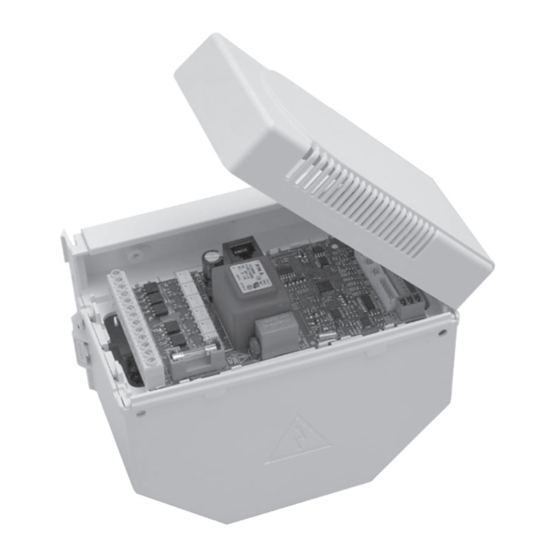
- Page 15 The electric box is formed by a box of self- tola di materiale plastico autoestinguente extinguishing plastic V0, in which is housed in classe V0, in cui è alloggiata la scheda the electronic board POWER IDROLAN. elettronica POWER IDROLAN. Fixing the electric box: Fissaggio del quadro elettrico:...
- Page 16 4. DIMENSIONI - DIMENSIONS IT IT 98,3 90,5 Ø 4,5 145,5...
- Page 17 5. Sostituzione scheda POWER IdroLAN su fancoil IT IT IT IT 5. Replace card POWER IdroLAN of fan coils 1. Aprire il coperchio del quadro di coman- 1. Open the control panel mounted on the do installato sul ventilconvettore fan coil 2.
- Page 18 Il termoregolatore EMMETI, della serie The EMMETI thermoregulator, of the series “POWER IDROLAN”, è stato progettato per "POWER IDROLAN", is designed for the con- il controllo e la gestione di Unità. trol and management of units. Terminali (ventilconvettori, cassette idro-...
- Page 19 For the management of the features of Per la gestione delle funzionalità della POWER IDROLAN, there is a latest genera- POWER IDROLAN è stato impiegato un tion microprocessor with 32K flash memory microprocessore di ultima generazione con...
-
Page 20: Identificazione / Identification
Il termoregolatore POWER IDROLAN può The thermoregulator POWER IDROLAN can essere impiegato per la gestione di tutti i be used for the management of all EMMETI prodotti EMMETI ed è identificato da due products and it is identified by two codes. - Page 21 Installazione / Installation 8. CONNESSIONI / CONNECTIONS IT IT Il Termoregolatore POWER IDROLAN The POWER IDROLAN thermoregulator mette a disposizione molte funzionalità makes available many additional functions aggiuntive rispetto ai tradizionali controlli: with respect to the traditional controllers: • 5 Uscite ON/OFF •...
-
Page 22: Connessioni / Connections
Modbus network, up to a max- tramite rete Modbus, fino ad un massi- imum of 40 POWER IDROLANs, and the mo di 40 POWER IDROLAN, e relativa relative timer of the thermoregulator. Temporizzazione del funzionamento del Termoregolatore. - Page 23 CONSOLE ANALOGICA CONSOLE LCD ANALOGUE CONSOLE 8.1 Schema di collegamento tra Console 8.1 Electrical connection between LCD Con- LCD e varie Power IdroLAN sole and several Power IdroLAN cards Console LCD LCD Console Network Localbus (Broadcast) 2xAWG 24 4x AWG24...
- Page 24 8. CONNESSIONI / CONNECTIONS IT IT 8.2 Schema di collegamento tra Console 8.2 Electrical connection between Analogue Analogica e varie Power IdroLAN Console and several Power IdroLAN cards Console Analogica - Analogue Console Network Localbus - (Broadcast) 2xAWG 24 J6 SLAVE...
-
Page 25: Installazione / Installation
9. Input/output “POWER IDROLAN” IT IT 9.1 Ventilatore principale (uscite S1-S2-S3) 9.1 Main fan (outputs S1-S2-S3) Il termoregolatore “POWER IDROLAN” ha The thermoregulator “POWER IDROLAN” tre uscite indipendenti ( S1-S2-S3 ) per features three independent outputs ( S1- l’alimentazione delle rispettive velocità... - Page 26 9. Input/output “POWER IDROLAN” IT IT della banda proporzionale e, in presenza water). della sonda acqua, rapportando anche When the percentage on the proportional la temperatura acqua sul parametro P24 band exceeds 20%, the fan is activated at (considerato banda proporzionale dell’ac- the speed set manually or at the minimum qua).
- Page 27 Installazione / Installation 9. Input/output “POWER IDROLAN” IT IT 9.3 “Consenso ventilatore” 9.3 "Fan approval" Tale funzionalità consente l’attivazione del This function allows for the activation of the ventilatore solo quando la temperatura fan only when the water temperature is suf- dell’acqua è...
- Page 28 9. Input/output “POWER IDROLAN” IT IT "Auto-fan in base alla temperatura dell’Acqua" "Auto-fan according to the temperature of Water" Auto Fan speed Velocità Ventilatore Raffrescamento (estate) Heating (winter) Cooling (summer) Caldo (Inverno) Banda Proporzionale (P24) Banda Proporzionale (P24) Water Temperature...
- Page 29 Installazione / Installation 9. Input/output “POWER IDROLAN” IT IT - P24 (IsteH20 ) valore di banda proporzio- - P24 (IsteH20 ) proportional band value nale per la gestione delle velocità del for the management of the fan speeds in ventilatore in modalità AUTO e valore AUTO mode and hysteresis value of the d’isteresi di temperatura riferita al valore...
- Page 30 9. Input/output “POWER IDROLAN” IT IT 9.4 “Destratificazione” 9.4 “Destratification” La funzione “ destratificazione” viene uti- The "destratification" function is used in the lizzata nei casi in cui il ventilatore opera cases in which the fan is operating in "ther- in “modalità...
- Page 31 Installazione / Installation 9. Input/output “POWER IDROLAN” IT IT Tale funzione è condizionata dall’imposta- - P18 (OnDelay) delay (seconds) the start of zione dei seguenti parametri di setup: the fan with respect to the activation of the - P18 (OnDelay) ritardo ( secondi ) d’avvia- valves.
- Page 32 9. Input/output “POWER IDROLAN” IT IT 9.7 VH and VC outputs “hot and 9.7 Uscite VH e VC “valvola calda cold valve" e fredda” These outputs are used to supply the elec- Tali uscite sono utilizzate per l’alimentazione tro-thermal valves (230V~).
- Page 33 HEAT/Riscaldamento Cool/Raffrescamento Installazione / Installation 9. Input/output “POWER IDROLAN” IT IT Set-Point Set-Point 9.8 Uscite analogiche Hot e cold 9.8 Hot and cold analog “valvole modulanti ” outputs "modulating valves" Isteresi Isteresi Tali uscite (disponibili sui morsetti COM- These outputs (available on the terminals...
- Page 34 "AS" connector on the "POW- l’apposito sensore al connettore “AS” sulla ER IDROLAN" card and the sensor present in scheda “POWER IDROLAN” ed il sensore the CONSOLE is immediately excluded. presente nella CONSOLE viene automatica- mente escluso.
- Page 35 If no console has been connected to the Se non è stata collegata alcuna console thermoregulator POWER IDROLAN and the al termoregolatore POWER IDROLAN e lo latter is not configured as "SLAVE by Lo- stesso non è configurato come “SLAVE by cal-bus", an ambient temperature sensor...
- Page 36 10. Ingressi analogici / Analogic inputs IT IT 10.2 WATER temperature sensor 10.2 Sensore della temperatura dell’ACQUA Thermoregulator POWER IDROLAN, WS connector Termoregolatore POWER IDROLAN, This sensor consists of a thermistor (10K connettore WS 25°) encapsulated in a special rubber casing.
- Page 37 Installazione / Installation 10. Ingressi analogici / Analogic inputs IT IT Approval to fan and/or Limitation of the Summer/Winter Switch min. temperature of the coolant and/or De- (2 pipe system only) activation of the electric heater With 3-way elec- Without regulat- tric regulating With or without regulating valve ...
- Page 38 POWER IDROLAN, terminals 70-71 Attraverso questo ingresso, quando la By means of this input, when the POWER POWER IDROLAN è alimentata ed è in IDROLAN is powered and in comfort mode, modalità comfort, è possibile modificare il it is possible to change the ambient Setpoint...
- Page 39 11. Ingressi digitali / Digital inputs IT IT 11.2 Contatto Finestra 11.2 Window Contact POWER IDROLAN, morsetti 50-51 POWER IDROLAN, terminals 50-51 Attraverso questo ingresso, quando la PO- By means of this input, when the POWER WER IDROLAN è alimentata, è possibile IDROLAN is powered, it is possible to put the portare il dispositivo in modalità...
- Page 40 The thermoregulator POWER IDROLAN was (P35) to OFF. designed to be used in various types of sys- Il Termoregolatore POWER IDROLAN è sta- tems with different operating modes. This to progettato per poter essere impiegato flexibility is given by the availability of over in varie tipologie d’impianto e con svariate...
- Page 41 Installazione / Installation 12. Modalità di funzionamento / Operating mode IT IT 12.1 Mode “Changeover ” 12.1 “Changeover" mode Tramite l’apposito parametro “P21” si può By means of the dedicated parameter "P21", impostare un “cambio stagione”: you can set a "change of season": Manuale, Centralizzato, Temp.
- Page 42 12. Modalità di funzionamento / Operating mode IT IT 3) Temp. Ambiente (impianto a 4 tubi) 3) Ambient Temp. (4 pipe system) In questa modalità si ha ( in automa- In this mode, the HEATING or COOL- tico) lo stato di RISCALDAMENTO ING state is activated automatically o RAFFREDDAMENTO in base al depending on the ambient tempera-...
- Page 43 Installazione / Installation 12. Modalità di funzionamento / Operating mode IT IT Esempio di regolazione in base alla temp. ambiente BANDA = 4 K NEUTRA - BN/2 + BN/2 Temp.in aumento CIRCUITO CALDO Temperatura in diminuzione 19,5° C 24,5° C Temp.
- Page 44 Recommended for big environments with di condizionamento provviste di POWER more than one air conditioning unit with IDROLAN e comandate da una sola Console POWER IDROLAN and controlled by a single (Analogica o LCD). Console (Analog or LCD). In sostanza,viene creata un piccola rete”...
- Page 45 Installazione / Installation 12. Modalità di funzionamento / Operating mode IT IT FUNZIONALITÀ FUNCTIONS Il termoregolatore “slave” può solo The "slave" thermoregulator can only ricevere comandi dal proprio master receive commands from its master (not (non trasmetterli) e se ha collegate le send them) and if the following sen- sonde: AS e/o WS, 30-31 (contact mo- sors are connected: AS and/or CS and/...
-
Page 46: Modalità Di Funzionamento
12. Modalità di funzionamento IT IT 12.4 Parametri di set-up CONSOLE LCD MODBUS Valore di Parametro Register U.M. Range default Var.SetPoint P00 deltEco 6.0°C 1000 °C/10 20:150 EconomyValue 0=Therm P02 fan Fan mode Therm 1002 1=Cont. 2= Auto Fan off: P03 destOff 1003 1:60... - Page 47 Installazione / Installation 12. Modalità di funzionamento IT IT DESCRIZIONE Variazione del setpoint di temperatura nello stato”economy” Modalità di funzionamento ventilatore,in “continuo”: il ventilatore è sempre in funzione alla velocità impostata manualmente. Se impostato “Auto”, raggiunto il setpoint, gira alla velocità...
- Page 48 12. Modalità di funzionamento IT IT 12.4 Parametri di set-up CONSOLE LCD MODBUS Parametro Valore default Register U.M. Range MinSetPoint P12minSPt 10.0°C 1012 °C/10 40:200 Air Temperat MaxSetPoint P13maxSPt 30,0°C 1013 °C/10 200:350 Air Temperat P16deadBan Dead Band 4,0°C 1016 °C/10 10:100 Proportional...
- Page 49 Installazione / Installation 12. Modalità di funzionamento IT IT DESCRIZIONE Limite min del setpoint della temperatura ambiente Limite max del setpoint della temperatura ambiente Valore dell’ampiezza della banda neutra Valore dell’ampiezza della banda proporzionale Ritardo d’avviamento del ventilatore principale Ritardo d’arresto del ventilatore principale Tipologia d’impianto 2 o 4 tubi 0=Manuale: selezione manuale...
- Page 50 12. Modalità di funzionamento IT IT 12.4 Parametri di set-up CONSOLE LCD MODBUS Parametro Valore default Register U.M. Range Hysteresis P24isteH20 6,0°C 1024 °C/10 10:200 Water Temp. WS min.Fluid P28minTflu 1.5°C 1028 °C/10 -100:200 Temp.Cooling WS Hysteresis P29istTflu 7,0°C 1029 °C/10 0:100 Fluid limit...
- Page 51 Installazione / Installation 12. Modalità di funzionamento IT IT DESCRIZIONE Isteresi di temperatura riferita al valore della sonda acqua per: riattivazione resistenza e per disattivazione “consenso ventilatore “ Temperatura min. di raffreddamento (Quando la temperatura dello scambiatore(sonda “WS”) scende sotto questo valore, l’uscita della valvola fredda viene disattivata) Isteresi della temperatura minima di raffreddamento (per la riabilitazione della valvola fredda) Valore di Temp.
- Page 52 12. Modalità di funzionamento 12.4 Parametri di set-up CONSOLE LCD MODBUS Parametro Valore default Register U.M. Range 0=ON ALL Occupancy 1=SUMMER P37economy cont ON ALL 1037 2=WINTER Iinput 70-71 3=OFF 0=WS Input type for P38sensH2O 1038 1=CS ProbeH2O 2=WS+CS OffSet 20-21 P43ofS2021 0,0°C 1043...
- Page 53 IT IT DESCRIZIONE Indica lo stato d’attivazione della funzione ECONOMY (dalla console LCD e dall’ingresso 70-71) 0=attiva funz. ECONOMY sempre (contatto N.O.) 1=attiva funz. ECONOMY solo estate (contatto N.O.) 2=attiva funz. ECONOMY solo inverno (contatto N.O.) 4=Disable Ingresso della sonda di consenso del ventilatore (connettore WS, CS ) selezionando l’ingresso CS, su tale sonda si avrà...
-
Page 54: Operating Mode
12. Operating mode 12.4 Set-up parameters LCD CONSOLE MODBUS Parameter Default value Register U.M. Range Var.SetPoint P00 deltEco 6.0°C 1000 °C/10 20:150 EconomyValue 0=Therm P02 fan Fan mode Therm 1002 1=Cont. 2=Auto Fan off: P03 destOff 1003 1:60 destratification Destratification P04 destOn 1004 0:60... -
Page 55: Installation
Installation DESCRIPTION Variation of the temperature setpoint in the "economy" state Operating mode fan, in "continuous": The fan is always running at a manually set. If set to "Auto", reached the setpoint, running at the speed min .. If set to "thermostat" the fan stops on reaching the set point. - Page 56 12. Operating mode 12.4 Set-up parameters LCD CONSOLE MODBUS Parameter Default value Register U.M. Range MinSetPoint P12minSPt 10.0°C 1012 °C/10 40:200 Air Temperat MaxSetPoint P13maxSPt 30,0°C 1013 °C/10 200:350 Air Temperat P16deadBan Dead Band 4,0°C 1016 °C/10 10:100 Proportional P17propBan 3,0°C 1017 °C/10...
- Page 57 Installation DESCRIPTION Minimum ambient temperature setpoint limit Maximum ambient temperature setpoint limit Amplitude value of the neutral zone Amplitude value of the proportional band Main fan start delay Main fan stop delay System type 2 or 4 pipes 0=Manual: manual selection (from LCD CONSOLE or from Modbus) of the operating mode (HEATING, COOLING, DEHUMIDIFICATION or VENTILATION).
- Page 58 12. Operating mode 12.4 Set-up parameters LCD CONSOLE MODBUS Parameter Default value Register U.M. Range Hysteresis P24isteH20 6,0°C 1024 °C/10 10:200 Water Temp. WS min.Fluid P28minTflu 1.5°C 1028 °C/10 -100:200 Temp.Cooling WS Hysteresis P29istTflu 7,0°C 1029 °C/10 0:100 Fluid limit 0=OFF 7=0°C 1=-12°C...
- Page 59 Installation DESCRIPTION Temperature hysteresis referred to the value of the water sensor for: the reactivation of the resistance and the deactivation of the "fan approval" Minimum cooling temperature (When the temperature of the exchanger ("WS" sensor" drops below this value, the cold valve output is deactivated) Hysteresis of the minimum cooling temperature (for the re-enabling of the cold valve) Temperature value for the activation of the antifrost function: 04-outTamb (opening of hot valve and activation of external relay), 12-T.air ext (activation of external relay)
- Page 60 12. Operating mode 12.4 Set-up parameters LCD CONSOLE MODBUS Parameter Default value Register U.M. Range 0=ON ALL Occupancy 1=SUMMER P37economy cont ON ALL 1037 2=WINTER Iinput 70-71 3=OFF 0=WS Input type for P38sensH2O 1038 1=CS ProbeH2O 2=WS+CS OffSet 20-21 P43ofS2021 0.0°C 1043 1/10...
- Page 61 Installation DESCRIPTION Indicates the activation state of the ECONOMY function (from the LCD console and from the input 70-71) 0= activate ECONOMY always (contact N.O.) 1= activate ECONOMY only summer (contact N.O.) 2= activate ECONOMY only winter (contact N.O.) 4= Disable input of the fan approval sensor (connector WS CS);...
- Page 62 Standby (SYSTEM OFF) In tale stato sono disabilitate le varie uscite In this state, the various outputs of the della “POWER IDROLAN” ad esclusione del- "POWER IDROLAN" are disabled, except for la funzione antigelo e della comunicazione the antifrost function and the Modbus com- Modbus.
- Page 63 13. Stati del termoregolatore Installazione / Installation IT IT States of the Controller “POWER IDROLAN” • accendere il dispositivo premendo il tasto or heating by pressing the button e selezionare la modalità di funzionamen- • briefly press the button to activate or to in raffreddamento o in riscaldamento deactivate the "Economy"...
- Page 64 LED ROSSO E VERDE alternati Òstato di zona neutra LED ROSSO E VERDE lampeggiante stato valvola fredda e calda aperta LED ROSSO E VERDE SPENTI Ò POWER IDROLAN fuori uso (non alimentata o danneggiata) LED GIALLO fisso Ò collegamento rete ModBus LED GIALLO lampeggiante Ò...
- Page 65 RED and GREEN LED alternating Òstate of neutral zone RED and GREEN LED flashing cold and hot valve open RED AND GREEN VALVES OFF Ò POWER IDROLAN out of use (not powered or damaged) YELLOW LED fixed Ò connection to ModBus network YELLOW LED flashing Ò...
- Page 66 13. Stati del termoregolatore “POWER IDROLAN” 13.5 Visualizzazione degli Input/Output CONSOLE LCD MODBUS Valore Parametro Register U.M. Range di default 03-OutSetP -10 :40 3003 °C/10 -100:400 04-OutTamb -30 : 90 3004 °C/10 -300:900 05-InputAS -30 :90 3005 °C/10 -300:900 10-InputWS...
- Page 67 IT IT DESCRIZIONE Valore di temperatura da raggiungere Valore di temp. aria di riferimento per la regolazione Valore letto dalla sonda di temp. Remota "AS" Valore letto dalla sonda di temp. dell’acqua “WS” Valore di temp. dall’ingresso 60-61 Sommatoria delle ore di funzionamento del ventilatore in step da 10 ore Ore di funzionamento del ventilatore dall’ultima pulizia del filtro aria (questo parametro viene resettato ad ogni pulizia del filtro da CONSOLE LCD ) Stato di funzionamento del ventilatore principale...
- Page 68 13. Stati del termoregolatore “POWER IDROLAN” 13.5 Visualizzazione degli Input/Output CONSOLE LCD MODBUS Valore Parametro Register U.M. Range di default 0=OPEN 23-Inp7071 OPEN CLOSE 3023 1=CLOSE 0=OPEN 24-Inp5051 OPEN CLOSE 3024 1=CLOSE 0=OPEN 25-Inp3031 OPEN CLOSE 3025 1=CLOSE 29-codePB 3029...
- Page 69 IT IT DESCRIZIONE Stato dell’ingresso 70-71 “economy” Stato dell’ingresso 50-51 “window” Stato dell’ingresso 30-31 (surriscaldamento del motore) Codice firmware POWER IDROLAN Codice firmware CONSOLE LCD Impostazione dello stato del regolatore Impostazione delle velocità del ventilatore Impostazione del setpoint della temperatura ambiente Impostazione del modo di funzionamento Impostazione del setpoint dell’umidità...
- Page 70 13. States of the Controller “POWER IDROLAN” 13.5 Viewing Input / Output LCD CONSOLE MODBUS Default value Parameter Register U.M. Range di default 03-OutSetP -10 :40 3003 °C/10 -100:400 04-OutTamb -30 : 90 3004 °C/10 -300:900 05-InputAS -30 :90 3005 °C/10...
- Page 71 Installation DESCRIPTION Temperature value to be reached Reference air temp. value for the settings Value read by the remote temp. sensor “AS” Value read by the water temp. sensor “WS” Value of temp. from input 60-61 Cumulative operating hours of the fan in 10 hour steps Hours of operation of the fan from the last time the air filter was cleaned (this parameter is reset every time the filter is cleaned from the LCD CONSOLE) Operating state of the main fan...
- Page 72 13. States of the Controller “POWER IDROLAN” 13.5 Viewing Input / Output LCD CONSOLE MODBUS Default value Parameter Register U.M. Range di default 0=OPEN 23-Inp7071 OPEN CLOSE 3023 1=CLOSE 0=OPEN 24-Inp5051 OPEN CLOSE 3024 1=CLOSE 0=OPEN 25-Inp3031 OPEN CLOSE 3025...
- Page 73 DESCRIPTION State of of input 70-71 "economy" State of input 50-51 "window" State of input 30-31 (overheating of motor) Firmware code POWER IDROLAN Firmware code CONSOLE LCD Setting the state of the thermoregulator Setting the speed of the fan Setting the setpoint of the ambient temperature...
- Page 74 13. Stati del termoregolatore IT IT States of the Controller “POWER IDROLAN” 13.6 Allarmi / Warning 13.6 Warning Eventuali stati o eventi anomali sono gestiti Any abnormal states or events are man- e codificati dal Termoregolatore come di se- aged and coded by the Thermoregulator as guito riportato.
- Page 75 This anomaly can be solved by performing - cod. W00 "vari Warning attivi” an accurate verification of the compliance of the electrical connections between the LCD Console and the POWER IDROLAN. N.B. Il simbolo lampeggiante, sta ad indicare - cod. W00 "various Warnings active”...
- Page 76 Respect the environment! For a correct disposal, the different materials must be divided and collected according to the regulations in force. EMMETI Spa Via B. Osoppo, 166 - 33074 Vigonovo frazione di Fontanafredda (PN) - Italy Tel. 0434-567911 - Telefax 0434-567901 Internet: http://www.emmeti.com...
Need help?
Do you have a question about the POWER idroLAN and is the answer not in the manual?
Questions and answers