Advertisement
Quick Links
Advertisement

Related Manuals for Shini STM-D


Summary of Contents for Shini STM-D
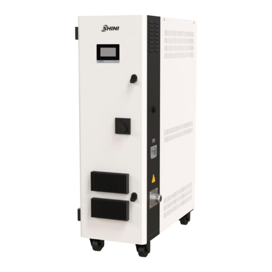
- Page 1 STM-D Oil Heater Date: Jun. 2024 Version: Ver.I...
- Page 2 Contents General Description ..................5 1.1 Coding Principle ..................6 1.2 Feature ....................6 1.3 Options ....................6 1.4 Pump Performance ................. 8 1.5 Reference Formula of Mould Controllers Model Selection ...... 8 1.6 Safety Regulations .................. 8 1.6.1 Safety Signs and Labels ............... 8 1.6.2 Signs and Labels ................
- Page 3 4.5.3 Output Inquiry ................26 4.5.4 Input Inquiry ................26 4.5.5 Controller Version Inquiry ............27 4.6 Password Management ................ 27 4.6.1 Login ................... 27 4.6.2 Password Modification ..............28 4.7 Setting Screen ..................29 4.7.1 User Parameter Setting .............. 29 4.7.2 Action Setting ................
- Page 4 Table 4-4:Water Refilling Time of Each Water Heater Model ......22 Picture Index Picture 1-1:Oil Heater STM-D ................5 Picture 1-2:Pump Performance ................. 8 Picture 2-1:Working Principle ................13 Picture 3-1: Installation Space ................14 Picture 3-2: Mould and Water Coupling 2 ............15 Picture 6-1: Open the Covers 1 .................
- Page 5 Read this manual carefully before operation to prevent damage of the machine or personal injuries. The STM-D series oil heaters are used to heat up the mould and maintain this temperature, although they can be used in other similar applications. High...
- Page 6 Options Double-stage First Two Codes: Heater Power (kW) Last Two Codes: Pump Power (×10 Shini Mould Temp. Controllers Feature l Adopt SSR solid-state relay with heating output, the max. heating temperature can reach 200℃, with the precision of ±0.5℃. l Adopt a vertical structure with a small footprint.
- Page 7 Chapter 6, which contains service instructions intended for service engineers. Other chapters contain instructions for the daily operator. Any modifications of the machine must be approved by SHINI in order to avoid personal injury and damage to machine. We shall not be liable for any damage caused by unauthorized change of the machine.
- Page 8 Pump Performance Flow rate (L/min) Picture 1-2:Pump Performance Reference Formula of Mould Controllers Model Selection Heater Power (kW) = mould weight (kg) × mould specific heat (kcal/kg℃) × temperature difference between mould and environment (℃) × safety coefficient / heating duration / 860 Note: safety coefficient can select a value from 1.3 to 1.5.
- Page 9 The unit is designed to endure high temp, and high pressure. For safe operation, do not remove the covers or switches. Attention! The unit should be operated by qualified personnel only. During operation, avoid wearing gloves or clothes that may cause danger. Turn off main switch when power supply is off.
- Page 10 Please according to schedule to make regular maintenance. Oil outlet valve: oil discharge outlet for renewing oil. High liquid level: the highest oil level to which machine can reach under room temperature. From mould: connector for circulating water/oil coming from mould. To mold: connector for circulating water/ oil to go to mould.
- Page 11 The following statements clarify the responsibilities and regulations born by any buyer or user who purchases products and accessories from Shini (including employees and agents). Shini is exempted from liability for any costs, fees, claims and losses caused by reasons below: 1) Any careless or man-made installations, operation and maintenances upon machines without referring to the Manual prior to machine using.
- Page 12 3) Any operational actions that are not authorized by Shini upon machine, including adding or replacing accessories, dismantling, delivering or repairing. 4) Employing consumables or oil media that are not appointed by Shini. 12(62)
- Page 13 Structure Characteristics and Working Principle Working Principle Level switch Solenoid valve Filter Cooling water inlet Oil tank Cooler Ball valves Pump Thermal sensor Heater Pressure meter Ball valve(oil) Picture 2-1:Working Principle The high temperature oil returns to the heater through the pipeline, and then goes into the mould and continues the circle.
- Page 14 3. Installation and Debugging Installation Space During installation of the machine, keep at least 500mm installation space around the machine as shown by the picture. Do not install the machine in a position crowded with other objects. This would cause inconvenience to operation, maintenance and repair.
- Page 15 Cooling Water Outlet Cooling Water Inlet Picture 3-2: Mould and Water Coupling 2 Table 3-1: Cooling Water Inlet and Outlet Spe. Model Cooling Water Inlet Cooling Water Outlet Connector Type Φ13mm(ext. dia.) Φ13mm(ext. dia.) STM-607D/910D Pagoda type Φ16mm(ext. dia.) Φ13mm(ext. dia.) STM-1220D Pagoda type Notice:...
- Page 16 7) Please refer to electrical drawing of each model to get the detailed power supply specifications Options Installation 3.4.1 Installation Steps for Options Water Manifold (Dewaxing) 1) Install copper joint to the level valve. 2) Install level valve with copper joint to the dewaxing water manifold. 3) Install water manifold to the machine.
- Page 17 1) Install copper joint to the level valve. 2) Install level valve with copper joint to the welding water manifold. 3) Install water manifold to the machine. 4) Connect water manifold with manifold joint via screws. 5) Install Teflon to copper joint. Note: For the operating temperature not higher than 200 ℃...
- Page 18 Operation Guide Control Panel After the system is powered on, the panel displays the startup screen, as below: Picture 4-1:Startup Screen Main Screen 4.2.1 Standby Screen Picture 4-2:Standby Screen(1) 18(62)
- Page 19 Picture 4-3:Standby Screen(2) Table 4-1:Standby Screen Icon & Press Key Description Function Icon Name Description Type When the system failure occurs, it will flash on the main interface. Click to enter and Fault inquiry press key query current fault information; When there’s no fault in the system, press to enter the "Historical Faults"...
- Page 20 display Standby Display machine running status. only Display the medium temp. returned from the Return medium display mould, which is optional function. When this temp. only function is not optional, it displays gray. Display the medium real-time pressure, and the Outlet medium display...
- Page 21 Picture 4-4:Operation Screen Table 4-2:Operation Screen Icon & Press Key Description Icon Name Description Pump rotating This icon indicates the unit starts pump rotating/reverse /reverse rotating rotating. This icon indicates the unit starts the Heating/cooling temp. heating control. The bottom is heating percentage. Startup and Shutdown 4.3.1 Start-up Steps 1) Connect the pipeline from the water heater’s water outlet and inlet to the...
- Page 22 (The values of various models are as follows) Table 4-3: Upper Limit Temp. and Maximum Temp. of Each Model Model Upper Limit Temp. Lower Limit Temp. STM/STM-D 200°C STM-HT 300°C STM-W/STM-WF/STM-WE/STM-W-D 120°C Default value:0°C...
- Page 23 STM-607W/W-D/PW STM-3650W STM-1220W/W-D/PW/WF/ STM/STM-D Model /PW-D/HPW/WF /STM-3650WF STM-2440W/STM-2430WF STM-HT STM-910W/W-D//WF /STM-4875WF 120S 180S 4.3.2 Shutdown 1) In the standby screen, press the < Forced Cooling > button to turn off the heating output, and the cooling is 100% on. 2) When the temp. drops below 50 ℃, press the < Forced Cooling > button to turn off the forced cooling, and then press the <...
- Page 24 ALARM Output medium pressure sensor No.1 fault 2021/01/15 13:42:33 Upper page Next page Silence Fault reset Picture 4-7:Current Fault Inquiry Screen Table 4-5:Current Fault Inquiry Screen Icon Key Description Press Key Key Name Description Fault reset After trouble-shooting, press this key to reset the fault. Silence Eliminate the system alarm sound Turn the page to query the fault information, gray key can’t be...
- Page 25 Inquiry Screen In the "Operation" screen, click the < Setting > button to enter the "User Setting" screen, and click the < Inquiry> button to enter the inquiry screen. Inquiry Picture 4-9:User Setting Screen 4.5.1 Data Inquiry Picture 4-10:Data Inquiry Screen 25(62)
- Page 26 It starts to count the unit running time after the assembly is finished, so the new machine will need some time for running. Check the current temperature or pressure of all probes in the system, and the system running time. 4.5.2 History Fault Inquiry Picture 4-11:History Fault Inquiry Screen 4.5.3 Output Inquiry...
- Page 27 Picture 4-13:Input Inquiry Screen When the indicator is gray, it means that the corresponding switching value input is invalid When the indicator is green, it means that the corresponding switching value input is valid. 4.5.5 Controller Version Inquiry Picture 4-14:Version Inquiry Screen Take actual display as standard.
- Page 28 Table 4-6:User and Password Function Password (can be User Name Function modified) User none Enter【User Setting】screen Project 3588 Enter【Project Setting】【User Setting】screen Manufacturer 6361 Enter the【Manufacturer Set】interface 4.6.2 Password Modification In the "User Setting" screen, click < System Setting >, and then click < Modify User Password >, it can modify the user password;...
- Page 29 modification is not success. If the modified password is successful, it will pop up the prompt box of "Password Modified Successfully! Please be noted to save the new password! ". Setting Screen Picture 4-16:User Setting Screen 4.7.1 User Parameter Setting Click the <...
- Page 30 Local: Unit startup and shutdown can only be controlled locally. Start/stop local ~ local + Local + Remote: unit startup and shutdown can local Mode remote ~ remote both be controlled locally and remotely. Remote: Unit startup and shutdown can only be controlled remotely.
- Page 31 Picture 4-19:Timer Setting Screen Set the system time in the “clock” area. After the timer main switch is turned on, it can set the timing on/off process, as shown in picture below: Picture 4-20:Timing On/Off Setting Timer main switch: It is used to select the timing on/off function. After it is turned on, the user can check the main screen.
- Page 32 Picture 4-21:Timer Inquiry and Modification Screen 4.7.4 System Setting In the "User Setting" screen, click the < System Setting > button to enter the picture below: Picture 4-22:System Setting Screen Table 4-8:System Setting Table Set the backlight time Setting range is 0 ~ 255 secs. Language Chinese or English The default user password...
- Page 33 Picture 4-23:Data Download Screen 1) Temp. Data Download Picture 4-24:Temp. Data Download Screen Local data backup: copy the temp. data on the display board to the U disk (the data of display board can be saved for up to 48 hrs.). Copy the temperature data stored on the display board to the USB flash disk.
- Page 34 Picture 4-25:Alarm Record Download Screen 4.7.6 Project Setting In the "User Settings" screen, click the < Advanced Setting > button and enter the password to enter the “Project” screen. Picture 4-26:Project Screen 1. Project Parameter Setting Set project parameters, and the specification of each parameter refers to “Project Parameter Table”.
- Page 35 Picture 4-27:Project Parameter Setting Screen Table 4-9:Project Parameter Description Initial Setting Parameter Name Unit Remarks Value Range Control response 15.0 1~30 adjustment Ar Adjust PID control response ℃ Heating 0.1~200.0℃ proportional 46.4 32.2-392.0 band P Cooling The times of heating proportional proportional 0.1~20.0 band...
- Page 36 shut down and the PV temp. is less than the [Emptying Temp.]. High temp. water heater: without pump reverse running. ℃ 0-60.0 1.【Auxiliary heating output temp. difference】=0: Only use the main heating output. 2. 【Auxiliary heating output temp. difference】 !=0: 1) When the control temp.
- Page 37 value is set to 5 ℃ , and the exhaust solenoid valve’s opening time is set to 0.5 sec. After the water is refilled, when the temp. rises by every 5 ℃ , it needs to open the solenoid valve for 0.5 secs.
- Page 38 【temp. deviation alarm delay 】 secs., it alarms “Large return medium temp. difference”, make auto reset. 0: disable (2) After modifying [SV] or forced cooling, this fault will not be solved in previous temp. rises / drops. (1) |Return medium temp. – ℃...
- Page 39 alarm pressure alarm], it delays two secs., and alarms “High pressure”; 0: disable 1. If the machine fails to reach the set temp. of - 5 ℃ within the [heater alarm] time, it will give the "heater alarm", and continue to Heater alarm 0~999 Min.
- Page 40 Return medium Compensate measurement ℃ temp. -30.0~30.0 error of the return medium temp. compensation Return medium Compensate measurement ℃ temp. -30.0~30.0 error of the return medium temp. compensation Analog quantity Compensate pressure -10.0~10.0 measurement error compensation Analog quantity Compensation flow measurement -30.0~30.0 L/min error.
- Page 41 Reset Fault Name Detection Logic Remark Mode 1. Power-on detection Manual Pump overload 2.Pump overload input point is valid, and the alarm reset delays 2 secs. Stop and release. 1. Power-on detection 2. Alarm action: Manual EGO overheat reset EGO input point alarms delay 2 secs. effectively, and it opens the circuit breaker output point 1.
- Page 42 Oil machine: 1. Power-on detection 2. Detection method: When it detects there’s no signal input of the low liquid level, the alarm delays for two secs. High temp. water machine: Manual 1. Detect after the start-up 【water refilling time】 , if there’s Low liquid level reset no high liquid level signal input, it alarms for the “low...
- Page 43 1. Check whether the sensor input signal is normal. Flow sensor Manual When it alarms, the machine runs continuously. fault reset 2. AI2 input is defined as "disabled", disable the fault. 1. When it alarms, the machine runs normally. After troubleshooting, reset manually.
- Page 44 1. When it alarms, the machine runs normally. 2. PV-【SV】 >【High temp. deviation alarm】, it delays 2 secs., and gives high temp. alarm. PV- 【SV】 < 【High temp. deviation alarm】, it resets the fault automatically. Auto Too high temp. When the【High temp. deviation alarm】= 0, disable this reset function.
- Page 45 1. When it alarms, the machine runs automatically, and the circuit breaker opens. 2. PV-【SV】> 【Overheat release output temp.】, the circuit breaker opens, and it gives overheat alarm. When the【Overheat release output temp.】= 0, disable Manual Overheat alarm this function. reset Note: In order to prevent false alarm after modifying the set temp., the fault can only be solved after the PV temp.
- Page 46 1. When alarm occurs, the machine stops running. After troubleshooting, reset manually. 3-phase power 2. When powered on, it starts detection, the phase Manual phase reverse / reverse alarm delays 1.2m secs., and the phase shortage reset phase loss alarm delays 3 secs. If it needs to disable the on-board phase sequence detection, please set the project parameter [3-phase power detection] to "disabled".
- Page 47 Trouble-shooting Failures Possible reasons Solutions No power supply. Connect through power supply. LCD displays nothing Main power switch broken. Replace main switch. after switch on power Power circuit broken. Check electrical wires. and press ON/OFF Control circuit breaker tripped. Fix the fuse. key.
- Page 48 The mould circular water ball valve doesn’t open or pipe Check the ball valve and pipe. High pressure blocked. Replace the pressure switch. Poor pressure switch. Temp. window Abnormal sensor. Check and repair sensor. displays “----“ Once running, pump output indicator PCB output relay problems.
- Page 49 Maintenance and Repair Clean solenoid valve. Period: Trimonthly. Clean Y-type filter. Period: monthly. Clean the pipe heater, cooling pipe. Period: Every three months. Check the contactor. Period: Every three months. Pay attention to the following rules during maintenance: 1) Need at least two persons present when checking the machine. Let the machine cool down, turn off power supply, drain out the oil and water.
- Page 50 Picture 6-1: Open the Covers 1 2) Remove the four screws on the cover plate, lift the cover plate to open (Refer to the pictures below). Picture 6-2: Open the Covers 2 3) Open the cover of the control box (Open the door lock on the door plank with the key to open).
- Page 51 5) Clean soft water should be used as cooling water. Y type strainer is used in the strainer to stop impurities and pollutants entering into water pipe. 6) Impurities or pollutants may cause errors and bad temperature control. Clean Y type strainer periodically. 7) Cleaning steps: turn off power and cooling water supply.
- Page 52 Picture 6-6:Pipe Heater 1 2) Remove the pipe heater cover (Unlock the screw, loosen the wire fixture, and remove the cover). Picture 6-7:Pipe Heater 2 3) After cleaning the pipe heater, install the pipe heater to the machine according to above opposite orders. Cooling Pipes After long use of the machine, as it is heated by high temperature, the heat transfer oil would carbonize and accumulate on machine pipeline.
- Page 53 Picture 6-1:Cooling Pipes 1 2) Remove the cooling pipe (Unlock the screws, and remove the cooling pipe, as shown in the picture). Picture 6-2:Cooling Pipes 2 3) Use the thinner or cloth dipped with thinner to clean the cooling pipe. After the cleaning, put the cooling pipe in the cool place for thinner total volatilization.
- Page 54 Maintenance Schedule 6.6.1 About the Machine Model Manufacture date Ф Voltage Frequency Power 6.6.2 Installation & Inspection Check the installation space is enough as required. Check the pipes are correctly connected. Electrical installation Voltage: Fuse melting current: 1 Phase 3 Phase Check phase sequence of power supply.
- Page 55 Check damaged pipes. Clean process heater/cooler. Check indicator and buzzer. Replace the hot kerosene with a using temperature above 120~160 degree 6.6.7 Yearly Checking Replace the hot kerosene with a using temperature above 120 degree 6.6.8 3 year Checking PC board renewal. No fuse breaker renewal.
- Page 56 Appendix 1 STM Comm. Variable Table (1) Comm. STM Comm. Variables Protocol: MODBUS-RTU D-Map (40000 English Chinese Range Description Type ※ 1 (Different displays CONTROL PV. Control temp. -50 ~ 500 read only RET PV Return water temp. -50 ~ 500 depending on whether the read only temp.
- Page 57 ※ 2 (Operate it with bit DI STATUS Contact input status 0 ~ 255 address)(as shown read only Appendix 3) ※ 2 (Operate it with bit ALARM STATUS Alarm status 0 ~ 255 address)(as shown read only Appendix 3) ※ 2 (Operate it with bit CONTROL Control temp.
- Page 58 Backlight time 0 ~ 255 0 ~255 read /write RUN/RESET KEY RUN/RESET KEY 0, 1 write only AUTO-TUNING AUTO-TUNING KEY 0, 1 write only AUTO-START KEY AUTO-START KEY 0, 1 write only 1 = Key (button) SUCTION KEY SUCTION KEY 0, 1 write only operation.
- Page 59 ※1 (Different displays depending on whether the Cooling control zone 0 ~ 550℃ read /write temp. unit ° C has a decimal point.) Heating control cycle 1 ~ 100s read /write Cooling control cycle 1 ~ 100s read /write PHASE ALARM Phase detection 0, 1 Unuse (0), use(1)
- Page 60 temp. unit ° C has a decimal point.) Return water temp. -550 ~ RET TEMP BIAS read /write correction 550℃ Output water -550 ~ ENT TEMP BIAS read /write temp. correction 550℃ 2000(0), 2001(1), …, NOW YEAR 0 ~ 99 read /write Year setting 2099(99)
- Page 61 PASSWORD Password setting 0 ~ 9999 read /write Return water output 0, 1 RET/ENT DISP temp. Unuse (0), use(1) read /write Water refilling time 0 ~ 600s W-FILL TM T1 read /write Water refilling time 0 ~ 60s W-FILL TM T2 read /write Display control loop, control+ return medium,...
- Page 62 ENT PV Sensor -Over +Over AD Error ERROR Open Input REMOTE -Over +Over AD Error Open ERROR BUZZ AUTO-T AUTO-S SUCTION COOLIN SUCTIO power STATUS UNING TART D-Map (40000 Name +i.j) STATUS( SUCTI AUTO-T SUCTIO BUZZER AUTO-S COOLING UNING TART LED) Auxiliary Pump...
Need help?
Do you have a question about the STM-D and is the answer not in the manual?
Questions and answers