Table of Contents
Advertisement
Quick Links
Advertisement
Table of Contents

Related Manuals for Shini STM-F Series


Summary of Contents for Shini STM-F Series
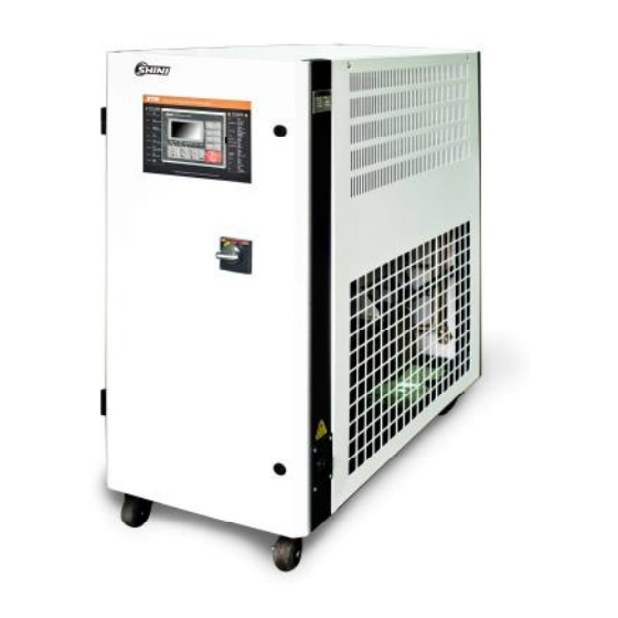
- Page 1 STM-F "Large Flow" Oil Heater Date: Feb. 2019 Version: Ver.D (English)
-
Page 3: Table Of Contents
Contents General Description ..................7 1.1 Coding Principle ..................8 1.2 Feature ....................8 1.3 Options ....................8 1.4 Technical Specifications ................ 10 1.4.1 Specification ................10 1.4.2 Pump Performance ..............11 1.4.3 Reference Formula of Mould Controllers Model Selection ..11 1.5 Safety Regulations ................ - Page 4 6.2 Solenoid Valve ..................37 6.3 Heater Pipe Cleaning ................38 6.4 Printed Circuit Board ................39 6.5 Display Terminal Connecting Diagram ..........41 6.6 Maintenance Schedule ................42 6.6.1 About the Machine ..............42 6.6.2 Installation & Inspection .............. 42 6.6.3 Daily Checking ................
- Page 5 Picture 4-7: Alarm Setting Screen..............25 Picture 4-8: Output Setting Screen ..............26 Picture 4-9: Temperature Setting Screen ............28 Picture 6-1: Y Type Strainer ................37 Picture 6-2: Solenoid Valve ................37 Picture 6-3: Heater Pipe 1 ................38 Picture 6-4: Heater Pipe 2 ................
- Page 6 6(43)
-
Page 7: General Description
Read this manual carefully before operation to prevent damage of the machine or personal injuries. STM-F series ''Large Flow'' oil heater mainly applied in extruder and rubber injection molding or other occasion requires large flow, strong cooling capability. Besides, it’s also applicable to the fields with same requirements. This series of heaters adopt indirect cooling method after return oil from the mould passed through the cooler. -
Page 8: Coding Principle
STM – xxxx F Oil “ Large Flow” First Two Codes: Heater Power (kW) Last Two Codes: Pump Power (×10 Shini Mold Temp. Controller 1.2 Feature l P.I.D. multi-stage temperature control system can maintain a mould temperature. l Maximum working temperature can reach 200 with control accuracy of ℃... - Page 9 Chapter 6, which contains service instructions intended for service engineers. Other chapters contain instructions for the daily operator. Any modifications of the machine must be approved by SHINI in order to avoid personal injury and damage to machine. We shall not be liable for any damage caused by unauthorized change of the machine.
-
Page 10: Technical Specifications
Technical Specifications 1.4.1 Specification Table 1-1: Specification Model STM-3050F STM-4575F Ver. Max temp.(℃) Heater Power (kW) Pump power (HP) Max. pump Flow (L/min) Max. pump pressure (bar) Heating TankNumber Main / Sub.Oil Tank (L) 100/18 14/51 Cooling Method Indirec Indirec Inlet/Outlet ( inch ) 1.5”... -
Page 11: Pump Performance
1.4.2 Pump Performance Picture 1-1: Pump Performance 1.4.3 Reference Formula of Mould Controllers Model Selection Heater Power (kW) = mould weight (kg) × mould specific heat (kcal/kg ) × ℃ temperature difference between mould and environment ( ) × safety coefficient ℃... -
Page 12: Safety Regulations
Safety Regulations Strictly abide by the following safety regulations to prevent damage of the machine or personal injuries. 1.5.1 Safety Signs and Labels Danger! The unit is designed to endure high temp, and high pressure. For safe operation, do not remove the covers or switches. Attention! The unit should be operated by qualified personnel only. -
Page 13: Signs And Labels
1.5.2 Signs and Labels Please according to schedule to make regular maintenance. Oil discharge valve: oil discharge port when machine is changing oil. High oil level: max. oil level of machine in constant temperature. From mould: connector for circulating water/oil of coming from mould Pump pressure meter: indicating actual pressure of system. -
Page 14: Operation Regulations
1. To maintain temperature stability, cooling water pressure must be higher than 2 bar at all time, but should never exceed 5 bar in any case. 2. Clean Y-shape Cooling Water Strainer periodically to ensure perfect cooling capacity. Water outlet: cooling water outlet Water inlet: cooling water intlet 1.5.3 Operation Regulations 1) When cooling water: qualified standard cooler for industrial use is... -
Page 15: Exemption Clause
Shini (including employees and agents). Shini is exempted from liability for any costs, fees, claims and losses caused by reasons below: 1. Before use of the machine, careless or man-made installations, operation and maintenances upon machine without referring to the Manual. -
Page 16: Structure Charateristics And Working Principle
2. Structure Charateristics and Working Principle 2.1 Working Principle Picture 2-1: Working Principle The high temperature oil returns to the machine and then be pressured by pump to the heaters. After being heated, oil will be forced to the mould and continue the circle. -
Page 17: Installation And Debugging
3. Installation and Debugging 3.1 Installation Space During installation of the machine, keep at least 500mm installation space around the machine as following picture. Don’t install the machine in a narrow or crowded place with other objects. This would cause inconvenience to operation, maintenance and repair. -
Page 18: Pipeline Connection
3.2 Pipeline Connection 1) Open the ball valve when machine is filling the oil. After the mould is filled with oil, close the valve and start up the machine. Picture 3-2: Ball Valve 2) After connect the cooling water outlet to drainage port, turn on the water source switch. -
Page 19: Operation Guide
4. Operation Guide Control Panel Picture 4-1: Control Panel Table 4-1: Control Panel Name Functions Remarks Heating(Main) Heating output indicator Heating(SUB) Auxiliary heating output indicator Cooling Cooling indicator Display pump positive Pump rotating action indicator Pump rotating Pump reverse action indicator direction reverse Water supply Water refilling indicator... - Page 20 Name Functions Remarks Auto-tuning Auto tuning key Reverse/Drain Reverse running/discharge Hold the button for 2 secs to enable force cooling. It stop heating while enable Mandatory cooling Forced cooling key 100% cooling. It stops after the temperutre drops below Cooling Temp. After press”...
- Page 21 Table 4-2:Error Type Error display Cause of Error Alarm Temp. control Board error Activated Stop Calib error Activated Stop Adc error Activated Stop Regulator error Rjc error Activated Stop Eeprom error Activated Maintain its status Phase error Default phase or phase reverse Activated Stop EGO Over temp.
-
Page 22: Menu Introduction
4.2 Menu Introduction Pictute 4-2: Menu Outline 22(43) -
Page 23: Machine Startup
4.3 Machine Startup 1) Switch on main power. Picture 4-3: Main Power Switch 2) Press <ON/OFF POWER> button of the controller to enter initial screen. Picture 4-4: Initial Menu 3) After confirming the temperature, press <run/stop> key to start the mould temperature controller. -
Page 24: Parameter Setting
conduct temperature control based on exisiting parameters before the Auto-tuning. Picture 4-5: Operation Screen 4.5 Parameter setting 1) Control Menu Press <MENU> key to enter menu selection screen, press ◄/► keys to control setting menu, press < Confirm Key > key to enter setting screen, see picture below. -
Page 25: Picture 4-7: Alarm Setting Screen
2) Alarm Setting Press <MENU> key to return menu selection screen, press ◄/►keys to alarm setting menu, press < Confirm Key > key to enter setting screen, as the table. All parameters are as below: Items Description Default PHASE Detection Prevent water pump reverse due to phase error Activate DEV1 ALARM... -
Page 26: Picture 4-8: Output Setting Screen
3) Output Setting Press the <Menu> key of the controller to return the selection screen of the menu, and press ◄/► keys to shift to output setting menu. Press <Confirm Key> to enter setting screen, and all the parameters are as below: Items Description Default... - Page 27 4) Temperature Setting Press <MENU> key to return menu selection screen, press ◄/► keys to temp. setting menu, press <Confirm> key to enter setting screen, as picture. All parameters are as below: Items Description Default STM-O: 200, STM-O-HT: 260, STM-607E:150(max.value is 200), UPPER LIMIT Software limit on maximum temperature...
-
Page 28: Picture 4-9: Temperature Setting Screen
Picture 4-9: Temperature Setting Screen 5) Time Setting Press <MENU> key to return menu selection screen, press ◄/► keys to time setting menu, press <Confirm> key to enter setting screen, as picture. The time has been adjusted before delivery. All the reserve time can be set according to actual production demands. - Page 29 Items Description Current time Format in YYMMDD Reserv week Weekly auto start/stop days Reserv time Auto start/ stop hour and minutes of the day. Format: xxHour xxMinutes Maint. time Machine maintenance time Work time Machine working hours Picture 4-9: Time Setting Screen 6) Communication Setting Press <MENU>...
- Page 30 Picture 4-10: Communication Setting Screen 7) Instrument setting Press <MENU> key to return menu selection screen, press ◄/►keys to machine setting menu, press <Confirm> key to enter setting screen, as picture. The parameters are set before delivery, and all the parameters can be adjusted according to actual demands.
- Page 31 Start delay for water unit to refill water in seconds. Automatically enable W-fill tm t1 after disable the breaker. Default 1 for oil unit, water unit as below table. Interval delay for water unit to refill water in seconds. Automatically W-fill tm t2 enable after disable the breaker.
-
Page 32: Stop The Machine
Picture 4-11: Machine Setting Screen 4.6 Stop the Machine 1) Press <forced cooling> key to shut down heating output, and cooling works 100%. 2) Wait until temperature drops to below 50℃, press < forced cooling > key to shut down forced cooling, then press <run/stop>key to stop operation. 3) Switch off the main power. - Page 33 Note: Pump motor rotating direction should be the same with the indicator. Note: Please do follow the above steps to turn on and off the machine. Fail to do so will reduce the lifespan of equipment. 33(43)
-
Page 34: Trouble-Shooting
5. Trouble-shooting Failures Possible reasons Solutions Did not connect through power supply. Connect through power supply. LCD displays nothing Main switch broken. Replace main switch. after switch on power Power supply wires Check electrical wires. press ON/OFF problems. Fix the fuse. key. - Page 35 Failures Possible reasons Solutions Short circuit of main circuit. Circuit breaker trips off Transformer short circuit or Check electrical wire. when turning on main connected with earth wire. Replace circuit breaker. power switch. Problems of circuit breaker. Circuit breaker trips off Pump motor coil short circuit.
-
Page 36: Maintenance And Repair
6. Maintenance and Repair Pay attention to the following rules during maintenance: 1) Need at least two persons present when checking the machine. Let the machine cool down, turn off power supply, drain out the oil and water. Make sure checking and maintenance space then start operation. 2) It’s dangerous that machine works in high temperature. -
Page 37: Y Type Strainer Cleaning
6.1 Y Type Strainer Cleaning Clean soft water should be used as cooling water. Filter screen is used in the strainer to stop impurities and pollutants entering into water pipe. Impurities or pollutants may cause errors and bad temperature control. It needs to clean the Y type strainer periodly. -
Page 38: Heater Pipe Cleaning
6.3 Heater Pipe Cleaning After long use of the machine and with high temperature, there will be clingage and limscale accumulated on heater pipe which lower the heating efficiency. At this time, it needs to clean the clingage and limscale accumulated on heater pipe. 1) Open the heater cover (Press the black switch downward, then open the heater cover. -
Page 39: Printed Circuit Board
6.4 Printed Circuit Board MAIN terminal board drawing (refer to next page for terminal position and number). ① SENSOR TERMINAL1 (sensor terminal) 2, 3 : control temp. sensor termnal 5, 6 : return water temp. sensor terminal 8, 9 : water outlet temp. sensor terminal 11, 12 : 1~5V input terminal ②... - Page 40 ⑥ DISPLAY CN (connect terminal for dispaly) Connect stub cable with STM100. ⑦ POWER TERMINAL (power supply terminal) 1 : FG terminal 2, 3 : power supply terminal (100~240VAC) 40(43)
-
Page 41: Display Terminal Connecting Diagram
6.5 Display Terminal Connecting Diagram DI TERMINAL (contactor input terminal) ① 1,2:RUN/STOP contactor input terminal COMM TERMINAL ( comm terminal) ② 1, 2, 3, 4: rs485 comm terminal 5:Earth terminal ③MAIN CN (MAIN earth terminal) Connet to the electric cables which also connected with stm100 TEST PIN ④... -
Page 42: Maintenance Schedule
Maintenance Schedule 6.6.1 About the Machine Model Manufacture date Voltage Ф V Frequency Hz Power 6.6.2 Installation & Inspection Check the installation space is enough as required. Check the pipes are correctly connected. Electrical installation Voltage: Fuse melting current: 1 Phase A 3 Phase Check phase sequence of power supply. -
Page 43: Yearly Checking
Check indicator and buzzer. Replace the hot kerosene with a using temperature above 120~160 degree 6.6.7 Yearly Checking Replace the hot kerosene with a using temperature above 120 degree 6.6.8 3 year Checking PCB board replacement No fuse switch replacement Note: (1) Y-type strainer has the function of filling water cooling protection effect, be sure the waterway are clear to avoid cooling failure.
Need help?
Do you have a question about the STM-F Series and is the answer not in the manual?
Questions and answers