Table of Contents
Advertisement
Quick Links
Advertisement
Table of Contents

Related Manuals for Shini STM-F Series


Summary of Contents for Shini STM-F Series
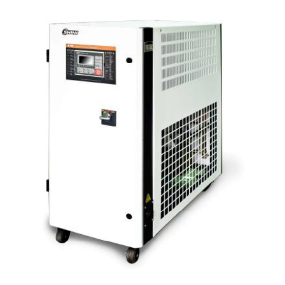
- Page 1 STM-F "Large Flow" Oil Heater Date: Jul. 2014 Version: Ver.B (English)
-
Page 3: Table Of Contents
Contents General Description .................. 7 1.1 Coding Principle ................... 8 1.2 Feature....................8 1.3 Technical Specifications..............10 1.3.1 Specification ................10 1.3.2 Pump Performance..............10 1.3.3 Reference Formula of Mould Controllers Model Selection..11 1.4 Safety Regulations ................12 1.4.1 Safety Signs and Labels ............12 1.4.2 Signs and Labels .............. - Page 4 2.3.7 Electrical Components Layout (STM-4575F) (230V) ....34 2.3.8 Electrical Components List (STM-4575F) (230V) ....35 2.4 Main Electrical Components Description..........36 2.4.1 Overload Relay................ 36 Installation and Debugging..............37 3.1 Installation Space................37 3.2 Pipeline Connection ................38 3.3 Power Connection................39 Operation Guide ..................
- Page 5 Table 1-2: Standard Water Quality ..............15 Table 2-1:Parts List (STM-4575F)..............19 Table 2-3: Heat Exchanger Parts List ............... 20 Table 2-4: Water Inlet Contector Parts List............21 Table 2-5: Oil pipe from pump parts list ............22 Table 2-6: Heating Hopper Parts List..............24 Table 2-7: Oil tank Parts List ................
- Page 6 Picture 3-2:Ball Valve..................38 Picture 3-3:Pipeline Connection ..............38 Picture 4-1:Control Panel ................40 Picture 4-2:Menu Outline ................43 Picture 4-3:Main Power Switch ..............44 Picture 4-4:Initial Menu .................. 44 Picture 4-5:Control Setting ................45 Picture 4-6:Alarm Setting ................46 Picture 4-7:Output Setting................
-
Page 7: General Description
Read this manual carefully before operation to prevent damage of the machine or personal injuries. STM-F series ''Large Flow'' oil heater mainly applied in extruder and rubber injection molding or other occasion requires large flow, strong cooling capability. Besides, it’s also applicable to the fields with same requirements. This series of heaters adopt indirect cooling method after return oil from the mould passed through the cooler. -
Page 8: Coding Principle
STM – xxxx F Oil “ Large Flow” First Two Codes: Heater Power (kW) Last Two Codes: Pump Power (×10 Shini Mold Temp. Controller 1.2 Feature Standard Configuration 1) It’s easy for dismantlement and maintenance. 2) P.I.D. full-digital temperature control system can reach maximum temperature at 200℃... - Page 9 Chapter 6, which contains service instructions intended for service engineers. Other chapters contain instructions for the daily operator. Any modifications of the machine must be approved by SHINI in order to avoid personal injury and damage to machine. We shall not be liable for any damage caused by unauthorized change of the machine.
-
Page 10: Technical Specifications
Technical Specifications 1.3.1 Specification Table 1-1:Specification Cooling Max. Max. Heating Main / Inlet/Outle Water Dimensions Pump pump Cooling Heater pump Mould Tank Sub. Inlet/Out (mm) Weight power Model Power Flow Coupling* pressure Method (HP) Number Oil Tank (inch) (H×W×D) (kg) (L / min) (kW) (inch) -
Page 11: Reference Formula Of Mould Controllers Model Selection
1.3.3 Reference Formula of Mould Controllers Model Selection Heater Power (kW) = mould weight (kg) × mould specific heat (kcal/kg ) × ℃ temperature difference between mould and environment ( ) × safety coefficient ℃ / heating duration / 860 Note: safety coefficient can select a value from 1.3 to 1.5. -
Page 12: Safety Regulations
Safety Regulations Strictly abide by the following safety regulations to prevent damage of the machine or personal injuries. 1.4.1 Safety Signs and Labels Danger! The unit is designed to endure high temp, and high pressure. For safe operation, do not remove the covers or switches. Attention! The unit should be operated by qualified personnel only. -
Page 13: Signs And Labels
1.4.2 Signs and Labels Please according to schedule to make regular maintenance. This is to indicate motor rotating direction. When phase reversal happens, the alarm sounds and indicator on control panel will indicate. Please exchange the place of (Attached on motor cover) two of the electrical wires to solve this problem. -
Page 14: Operation Regulations
From mould: connector for circulating water/oil of coming from mould Pump pressure meter: indicating actual pressure of system. To mold: connector for circulating water/ oil to go to mould. Oil inlet: Machine oil inlet 1. To maintain temperature stability, cooling water pressure must be higher than 2 bar at all time, but should never exceed 5 bar in any case. - Page 15 heater will stop working. At this moment, it needs to check overload reasons (phase shortage, pipe obstruction, broken bearing, etc.) After the system runs normally, press RESET on overload relay to rest the operation. 6) Before turn off the pump, wait until oil temperature falls blow 50℃. Or the service life of the unit would be affected.
-
Page 16: Exemption Clause
Shini (including employees and agents). Shini is exempted from liability for any costs, fees, claims and losses caused by reasons below: 1. Before use of the machine, careless or man-made installations, operation and maintenances upon machine without referring to the Manual. -
Page 17: Structure Charateristics And Working Principle
Structure Charateristics and Working Principle 2.1 Working Principle Picture 2-1:Working Principle The high temperature oil returns to the machine and then be pressured by pump to the heaters. After being heated, oil will be forced to the mould and continue the circle. In the process, if the oil temperature is too high, system will activate the solenoid valve to let cooling water cool down high temperature oil indirectly until the temperature is down to the system requirement. -
Page 18: Assembly Drawing
2.2 Assembly Drawing 2.2.1 Assembly Drawing (STM-4575F) Remarks: Please refer to material list 2.2.2 for specific explanation of the Arabic numbers in parts drawing. Picture 2-2:Assembly Drawing (STM-4575F) 18(62) -
Page 19: Parts List (Stm-4575F)
2.2.2 Parts List (STM-4575F) Table 2-1:Parts List (STM-4575F) Part No. Name STM-4575F Movable castor 3"* YW03000300200 Long door lock YW00000000100 Breaker interlock* YE41161500000 Big hinge-left CL203-1 YW06203100400 Controller MT100-01* YE81100010000 Oil inlet pipe of plate heat exchanger STM-4575F-ALL-16 Castor with brake 3" YW03000300000 Water inlet connector assembly STM-4575F-F-ALL... -
Page 20: Heat Exchanger Drawing
2.2.3 Heat Exchanger Drawing Picture 2-3:Heat Exchanger Drawing Table 2-3: Heat Exchanger Parts List Name Part No. Tonflon tube connector 1/2"PT×1/2"H(L) YW04121200000 Plate heat exchanger (BL20-78D) YW87957800000 Tonflon tube connector 3/4"PT×3/4"H BH12030400310 Copper pipe coupler 3/4"PT×3/4"PT BH12030400010 Solenoid valve 3/4"( KL 5231020S) * YE32312200000 * means possible broken parts. -
Page 21: Water Inlet Contector Assembly
2.2.4 Water Inlet Contector Assembly Picture 2-4:Water Inlet Contector Assembly Table 2-4: Water Inlet Contector Parts List Name Part No. General Copper nut BH12060703910 The 9th set of copper connector Tonflon tube connector 1/4H×1/4PT BH12010400410 Pipe coupler 1/2"PT×1/2"PT BH12010230110 Solenoid valve 1/2" (Airtac 2L15015A)* YE32501500000 Tonflon tube connector 1/2"PT×1/2"H BH12010200210... -
Page 22: Oil Pipe From Pump Assembly
2.2.5 Oil pipe from pump Assembly Picture 2-5:Oil pipe from pump Assembly Table 2-5: Oil pipe from pump parts list Name Part No. Oil pipe from pump BH12060703910 LOK-fitting 12mm×1/2''PT YW05121200000 * means possible broken parts. ** means easy broken part. and spare backup is suggested. Please confirm the version of manual before placing the purchase order to guarantee that the item number of the spare part is in accordance with the real object. -
Page 23: Heating Hopper Assembly
2.2.6 Heating Hopper Assembly Picture 2-6:Heating Hopper Assembly 23(62) - Page 24 Table 2-6: Heating Hopper Parts List Name Part No. Pipe coupler 1/2"PT×1/2"PT BH12010230110 Stainless steel ball valve 1/2"* YW50010200200 LOK-fitting connector 12mm×1/2''PT YW05121200000 Heating tank insulation cotton 5 Heating tank insulation cotton 6 Heating tank insulation cotton 3 Heating tank Heating tank insulation cotton 2 Copper pipe coupler 1/4×1/4(S-08) BH12010400110...
-
Page 25: Oil Tank Assembly
2.2.7 Oil Tank Assembly Picture 2-7:Oil tank drawing Table 2-7: Oil tank Parts List Name Part No. Oil tank LOK-fitting connector 12mm×1/2''PT YW05121200000 Tonflon tube connector 1/4H×1/4PT BH12010400410 Tonflon tube connector 3/8H×3/8PT(L) YW04030800300 Microswitch LXW5-1124 rod length 120mm* YE14152400000 Nut M5 YW64000600000 Flat head screw M5×30 YW60530000000... -
Page 26: Oil Discharge Connector Assembly
2.2.8 Oil Discharge Connector Assembly Picture 2-8:Oil Discharge Connector Assembly Table 2-8: Oil Discharge Connector Parts List Name Part No. 3/8"PT×∅13 Copper joint General copper nut BH12060703910 Water filling copper joint 1/4" Hopper bottom screw BH12010400710 Tonflon tube connector 3/8"PT×3/8"H(L) YW04030800300 * means possible broken parts. -
Page 27: Water Drainage Connector
2.2.9 Water Drainage Connector Picture 2-9:Water drainage connector drawing Table 2-9: Water Drainage Connector Parts List Name Part No. The 2 set of copper connector General copper nut BH12060703910 Tonflon tube connector 1/4H×1/4PT BH12010400410 Tonflon tube male thread connector 1/2H×3/8PT BH12010200310 * means possible broken parts. -
Page 28: Electrical Diagram
2.3 Electrical Diagram 2.3.1 Main Circuit (STM-4575F) (400V) Picture 2-10:Main Circuit 28(62) -
Page 29: Control Circuit (Stm-4575F) (400V)
2.3.2 Control Circuit (STM-4575F) (400V) Picture 2-11:Control Circuit (STM-4575F) (400V) 29(62) -
Page 30: Electrical Components Layout (Stm-4575F) (400V)
2.3.3 Electrical Components Layout (STM-4575F) (400V) Picture 2-12:Electrical Components Layout (STM-4575F) (400V) 30(62) -
Page 31: Electrical Components List (Stm-4575F) (400V)
2.3.4 Electrical Components List (STM-4575F) (400V) Table 2-10: Parts List (STM-4575F) (400V) Symbol Name Specification Part No. Breaker interlock 100A YE41110200000 Breaker YE40302503000 Q3 Q4 Q5 Breaker YE40303203000 Excitation Tripper YE40023560000 Contactor * 220V 50/60Hz YE00601800000 K2 K3 K4 Contactor ** 220V 50/60Hz YE00602822000 Heat overload relay... -
Page 32: Main Circuit (Stm-4575F) (230V)
2.3.5 Main Circuit (STM-4575F) (230V) Picture 2-13:Main Circuit ( STM-4575F)(230V) 32(62) -
Page 33: Control Circuit (Stm-4575F) (230V)
2.3.6 Control Circuit (STM-4575F) (230V) Picture 2-14:Control Circuit (STM-4575F)(230V) 33(62) -
Page 34: Electrical Components Layout (Stm-4575F) (230V)
2.3.7 Electrical Components Layout (STM-4575F) (230V) Picture 2-15:Electrical Components Layout (STM-4575) (230V) 34(62) -
Page 35: Electrical Components List (Stm-4575F) (230V)
2.3.8 Electrical Components List (STM-4575F) (230V) Table 2-11: Parts List (STM-4575F) (230V) No. Symbol Name Specification Part No. Breaker interlock 160A YE41161500000 Q2 Q3 Breaker YE40305003000 Q4 Q5 Excitation tripper YE40023560000 Contactor* 220V 50/60Hz YE00602722000 K2 K3 K4 Contactor** 220V 50/60Hz YE00503600000 Overload relay 20-25A... -
Page 36: Main Electrical Components Description
2.4 Main Electrical Components Description 2.4.1 Overload Relay At delivery, the overload relay is set for mannual reset. When motor overload occurs, stop the machine, then check and solve the problem. After that open the door of control box, press down the reset button of overload relay (if you can not press down the reset button, wait for one minute). -
Page 37: Installation And Debugging
3. Installation and Debugging 3.1 Installation Space During installation of the machine, keep at least 500mm installation space around the machine as following picture. Don’t install the machine in a narrow or crowded place with other objects. This would cause inconvenience to operation, maintenance and repair. -
Page 38: Pipeline Connection
3.2 Pipeline Connection 1) Open the ball valve when machine is filling the oil. After the mould is filled with oil, close the valve and start up the machine. Picture 3-2:Ball Valve 2) After connect the cooling water outlet to drainage port, turn on the water source switch. -
Page 39: Power Connection
3.3 Power Connection Make sure the power match the specification, then connect the power supply. Please check the voltage specification signs on machine’s nameplate carefully. The power supply must match the specification indicated on nameplate. The cable must match the section specification indicated in circuit diagram. 39(62) -
Page 40: Operation Guide
Operation Guide Control Panel Picture 4-1:Control Panel Table 4-1: Control Panel Name Functions Remarks Display showing LCD. After connect power, press “POWER ON/OFF”, initial POWER ON/OFF Power ON, OFF shift key screen is displayed and starts. Pls note that electrci shock may happen if power is on. - Page 41 Name Functions Remarks Auto-tuning can run during operation. AUTO-TUNING switch start and stop Auto-tuning cannot work under SUCTION and COOL operation. SUCTION remove medium (watre/oil) from molds. Can not start during SUCTION SUCTION relay switch start /stop key operation or cooling. After SUCTION turns “SUCTION relay”...
- Page 42 Table:4-2: Error Type Error display Reasons Alarm Temp.control Board error Activated Stop Calib error Activated Stop Controller error ADC error Activated Stop RJC error Activated Stop Eeprom error Activated Maintain its status Phase error Phase disconnect or phase reverse Activated Stop Over temp.
-
Page 43: Structure Of The Unit
Structure of the Unit Picture 4-2:Menu Outline 43(62) -
Page 44: Machine Startup
Machine Startup 1) Conenct pipeline from STM water in/outlet to the mold. (Refer to chapter 3.2 for pipeline connection) 2) Connect cooling water port and water backup port. (Refer to chapter 3.2 for pipeline connection) 3) Open all ball valves of the pipeline 4) Turn on main power switch. -
Page 45: Picture 4-5:Control Setting
Picture 4-5:Control Setting 7) Press MENU key to retuen to menu screen, press ◄/► key to select alarm setting then press SET to enter setting menu, see picture below. Here is parameter setting: • PHASE——used • DEV1 ALARM——0 (without temp. sensor) 5 (with temp. -
Page 46: Picture 4-6:Alarm Setting
• TURB ALARM——control temp.-10 • HEATER ALARM——based on auctual set value. If factory default value is 0, the heater alarm is not available. If there’s 7.5℃ difference compared with set temp. it will alarm. Picture 4-6:Alarm Setting 8) Press MENU key to return to menu screen, then press ◄/► key to select output setting and press SET key to enter setting screen, see picture below. -
Page 47: Picture 4-7:Output Setting
• OUTPUT MODE——heating or cooling control • SUB HEATING——0 (only 1 group of heater) • 5 (two or more groups of heaters) • COOLING TEMP——35 (When forced cooling starts, control temp. is lower than the set value, the forced cooling will stop automatically). -
Page 48: Picture 4-8:Temperature Setting
Picture 4-8:Temperature Setting 10) Press MENU key to return to menu screen, press ◄/► key to select time setting, press SET key to enter setting screen, see picture below. Time has been set before delivery; customers can set appointment time based on actual needs. -
Page 49: Picture 4-9:Time Setting
Picture 4-9:Time Setting 11) Press MENU key to return to menu screen, press ◄/► key to select communication setting, press SET key to enter setting screen, see picture below. If communication function is selected as an option, customers should set communication parameters based on actual needs. 49(62) -
Page 50: Picture 4-10:Communication Setting
Picture 4-10:Communication Setting 12) Press MENU key to return to menu screen, press ◄/► key to select device setting, press SET key to enter setting screen, see picture below. Before delivery, parameters have been set and customers can modify them based on actual needs. -
Page 51: Picture 4-11:Equipment Setting
Picture 4-11:Equipment Setting 13) Set mold temperature (if temp. has been set, this step can be ignored). Press SV key and control target value column will be flashing, press ◄/► key to move cursor then press ▲/▼ key to change values. Finally press SET key to confirm them. -
Page 52: Stop The Machine
control, Auto-tuning is needed if deviation of control is a little bit large. Press AT key and LED light begins flashing to start Auto-tuning. When flashing ends, Auto-tuning finishes and parameters will be automatically saved. During Auto-tuning, pressing AT key will exit Auto-tuning process; controller will conduct temperature control based on parameters set before Auto-tuning. -
Page 53: Trouble-Shooting
Trouble-shooting Failures Possible reasons Solutions Did not connect through power Connect through power supply. LCD displays nothing supply. Replace main switch. after switch on power Main switch broken. Check electrical wires. press ON/OFF Power supply wires problems. Fix the fuse. key. - Page 54 Problems of circuit breaker. Circuit breaker trips off Pump motor coil short circuit. Check pump motor. when pump running for Problems of circuit breaker. Replace circuit breaker. a while. Circuit breaker trips off Heater pipe short circuit or shell after heater output for Replace heater pipe.
-
Page 55: Maintenance And Repair
Maintenance and Repair Pay attention to the following rules during maintenance: 1) Need at least two persons present when checking the machine. Let the machine cool down, turn off power supply, drain out the oil and water. Make sure checking and maintenance space then start operation. 2) It’s dangerous that machine works in high temperature. -
Page 56: Y Type Strainer Cleaning
6.1 Y Type Strainer Cleaning Clean soft water should be used as cooling water. Filter screen is used in the strainer to stop impurities and pollutants entering into water pipe. Impurities or pollutants may cause errors and bad temperature control. It needs to clean the Y type strainer periodly. -
Page 57: Heater Pipe Cleaning
6.3 Heater Pipe Cleaning After long use of the machine and with high temperature, there will be clingage and limscale accumulated on heater pipe which lower the heating efficiency. At this time, it needs to clean the clingage and limscale accumulated on heater pipe. -
Page 58: Printed Circuit Board
6.4 Printed Circuit Board MAIN terminal board drawing (refer to next page for terminal position and number). ① SENSOR TERMINAL1 (sensor terminal) 2, 3 : control temp. sensor termnal 5, 6 : return water temp. sensor terminal 8, 9 : water outlet temp. sensor terminal 11, 12 : 1~5V input terminal ②... - Page 59 ⑥ DISPLAY CN (connect terminal for dispaly) Connect stub cable with STM100. ⑦ POWER TERMINAL (power supply terminal) 1 : FG terminal 2, 3 : power supply terminal (100~240VAC) 59(62)
-
Page 60: Display Terminal Connecting Diagram
6.5 Display Terminal Connecting Diagram ① DI TERMINAL (contactor input terminal) 1,2:RUN/STOP contactor input terminal ② COMM TERMINAL ( comm terminal) 1, 2, 3, 4: rs485 comm terminal 5:Earth terminal ③MAIN CN (MAIN earth terminal) Connet to the electric cables which also connected with stm100 ④... -
Page 61: Maintenance Schedule
Maintenance Schedule 6.6.1 About the Machine Model Manufacture date Ф Voltage V Frequency Hz Power 6.6.2 Installation & Inspection Check the installation space is enough as required. Check the pipes are correctly connected. Electrical installation Voltage: Fuse melting current: 1 Phase A 3 Phase Check phase sequence of power supply. -
Page 62: Yearly Checking
Check indicator and buzzer. Replace the hot kerosene with a using temperature above 120~160 degree 6.6.7 Yearly Checking Replace the hot kerosene with a using temperature above 120 degree 6.6.8 3 year Checking PCB board replacement No fuse switch replacement Note: (1) Y-type strainer has the function of filling water cooling protection effect, be sure the waterway are clear to avoid cooling failure.
Need help?
Do you have a question about the STM-F Series and is the answer not in the manual?
Questions and answers