Table of Contents
Advertisement
Quick Links
Advertisement
Table of Contents

Related Manuals for Shini STM-EB


Summary of Contents for Shini STM-EB
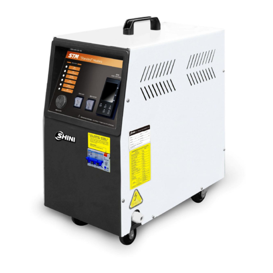
- Page 1 STM-EB "Budget" Heater Date: Apr, 2017 Version: Ver.A (English)
-
Page 3: Table Of Contents
Contents General Description ..................9 1.1 Coding Principle ..................10 1.2 Feature....................10 1.3 Option ....................10 1.4 Technical Specifications................ 12 1.4.1 Specification ................12 1.4.2 Pump Performance..............13 1.4.3 Reference Formula of Mould Controllers Model Selection..13 1.5 Safety Regulations ................14 1.5.1 Safety Signs and Labels ............. - Page 4 2.2.14 Heating Tank Parts List (STM-910-EB) ........29 2.2.15 Heating Tank Assembly Drawing (STM-910-EB)......30 2.2.16 Heating Tank Parts List (STM-910-EB) ........31 2.2.17 System Structure Drawing (STM-910W-EB)....... 32 2.2.18 Parts List (STM-910W-EB) ............33 2.2.19 Heating Tank Drawing (STM-910W-EB)........34 2.2.20 Parts List of Heating Tank (STM-910W-EB) .......
- Page 5 3.2 Power Supply ..................60 3.3 Operation Procedures ................61 3.3.1 Installation Steps for Options Water Manifold (Dewaxing)..61 3.3.2 Installation Steps for Options Water Manifold (Welding)..... 62 3.4 Mould and Water Coupling..............62 3.4.1 Add Heat Transfer Oil ..............64 Operation Guide ..................
- Page 6 Table 2-1: Parts List (STM-607-EB)..............20 Table 2-2: Heating Tank Parts List (STM-607-EB) ........... 22 Table 2-5: Parts List (STM-607W-EB) .............. 25 Table 2-6: Parts List (STM-910-EB)..............27 Table 2-11: Electrical Components List (STM-607-EB 400V)......39 Table 2-12: Electrical Components List (STM-607W-EB 400V) ....... 43 Table 2-13: Electrical Components List (STM-910-EB 400V)......
- Page 7 Picture 2-20: Control Circuit Dia. (STM-910-EB 400V) ........45 Picture 2-21: Electrical Components Layout (STM-910-EB 400V) ....46 Picture 2-22: Main Circuit Dia. (STM-910W-EB 400V) ........48 Picture 2-23: Control Circuit Dia. (STM-910W-EB 400V)........49 Picture 2-24: Electrical Components Layout (STM-910W-EB 400V) ....50 Picture 2-25: Main Circuit Dia.
- Page 8 8(76)
-
Page 9: General Description
Read this manual carefully before operation to prevent damage of the machine or personal injuries. STM-EB (W-EB) series are applicable for heating up the moulds and maintaining temperature, and they also can be used in other similar applications. Firstly, these... -
Page 10: Coding Principle
● STM-EB is equipped with low level protection. ● STM-W-EB is equipped with water inlet low pressure protection, system high pressure protection, automatic air exhaust and water supplying. - Page 11 Chapter 6, which contains service instructions intended for service engineers. Other chapters contain instructions for the daily operator. Any modifications of the machine must be approved by SHINI in order to avoid personal injury and damage to machine. We shall not be liable for any damage caused by unauthorized change of the machine.
-
Page 12: Technical Specifications
1.4 Technical Specifications 1.4.1 Specification Table 1-1: Specification Model STM-607EB STM-607W-EB STM-910-EB STM-910W-EB ℃ ℉ ℃ ℉ ℃ ℉ ℃ ℉ Max. Temp. 200S /392 120 /248 200 /248 120 /248 Pipe Heate (kW) Pump Power (kW) 0.55 0.75/0.92 0.75x2/0.92x2 Max. -
Page 13: Pump Performance
1.4.2 Pump Performance Picture 1-1: Pump Performance 1.4.3 Reference Formula of Mould Controllers Model Selection Heater Power (kW) = mould weight (kg) × mould specific heat (kcal/kg ) × ℃ temperature difference between mould and environment ( ) × safety coefficient ℃... -
Page 14: Safety Regulations
1.5 Safety Regulations Strictly abide by the following safety regulations to prevent damage of the machine or personal injuries. 1.5.1 Safety Signs and Labels Danger! The unit is designed to endure high temp, and high pressure. For safe operation, do not remove the covers or switches. Attention! The unit should be operated by qualified personnel only. -
Page 15: Signs And Labels
1.5.2 Signs and Labels From mould: connector for circulating water/oil coming from mould. To mold: connector for circulating water/ oil to go to mould. Water outlet: cooling water outlet. Water inlet: inlet for replenishing water and cooling water. 1.5.3 Operation Regulations 1) Before operation, make sure that cooling water is clean soft water without pollutants. -
Page 16: Exemption Clause
Shini (including employees and agents). Shini is exempted from liability for any costs, fees, claims and losses caused by reasons below: 1. Any careless or man-made installations, operation and maintenances upon machines without referring to the Manual prior to machine using. -
Page 17: Structure Characteristics And Working Principle
Structure Characteristics and Working Principle 2.1 Working Principle 2.1.1 System Flow for STM-607-EB (Indirect Cooling) Picture 2-1: STM-607-EB Working Principle The high temperature oil returns to the machine and then be pressured by pump to the heater. After being heated, oil will be forced to the mould and continue the circle. -
Page 18: System Flow For Stm-607W-Eb (Direct Cooling)
2.1.2 System Flow for STM-607W-EB (Direct Cooling) Picture 2-2: STM-607W-EB Working Principle The high temperature water returns from the mould to the temperature controller machine is pressurized by pump and conveyed to the heater. After being heated, it will be again flow to the mould to maintain the temperature, and this circle repeats. -
Page 19: Assembly Drawing
2.2 Assembly Drawing 2.2.1 System Structure Drawing (STM-607-EB) Remarks: Please refer to material list 2.2.2 for specific explanation of the Arabic numbers in parts drawing. Picture 2-3: System Structure Drawing (STM-607-EB) 19(76) -
Page 20: Parts List (Stm-607-Eb)
2.2.2 Parts List (STM-607-EB) Table 2-1: Parts List (STM-607-EB) Name Parts No. Black rubber caster 2” YW03000200000 Thick head screw M4×6 YW63040600000 Flat head screw M6×15 YW63061700000 Electrical supporting plate Cover plate Plastic operation panel YR40009500000 Flat head screw M6×10 YW62061000000 Oil exhast coupling Copper female connector For set No.1234... -
Page 21: Heating Tank Assembly (Stm-607-Eb)
2.2.3 Heating Tank Assembly (STM-607-EB) Remarks: Please refer to material list 2.2.4 for specific explanation of the Arabic numbers in parts drawing. Picture 2-4: Heating Tank Assembly (STM-607-EB) 21(76) -
Page 22: Heating Tank Parts List (Stm-607-Eb)
2.2.4 Heating Tank Parts List (STM-607-EB) Table 2-2: Heating Tank Parts List (STM-607-EB) Name Parts No. Copper Teflon pipe coupling 1/4H x 1/4PT BH12010400410 Screw M6 YW64000600300 Heater cover BL80091000120 inner hexagon screw M10 x 25 YW61102500000 Flat washer 10×25 YW66102500000 Spring washer 10 YW65010000000... -
Page 23: Cooling Water Inlet Connecting Assembly (Stm-607-Eb)
2.2.5 Cooling Water Inlet Connecting Assembly (STM-607-EB) Remarks: Please refer to material list 2.2.6 for specific explanation of the Arabic numbers in parts drawing. Picture 2-5: Cooling Water Inlet Connecting Assembly (STM-607-EB) 2.2.6 Parts List (STM-607-EB) Table 2-3: Parts List (STM-607-EB) Name Parts No. -
Page 24: System Structure Drawing (Stm-607W-Eb)
2.2.9 System Structure Drawing (STM-607W-EB) Remarks: Please refer to material list 2.2.10 for specific explanation of the Arabic numbers in parts drawing. Picture 2-7: System Structure Drawing (STM-607W-EB) 24(76) -
Page 25: Parts List (Stm-607W-Eb)
2.2.10 Parts List (STM-607W-EB) Table 2-5: Parts List (STM-607W-EB) Name Parts No. Thick head screw M4×6 YW63040600000 Flat washer 6 YW66061600000 Flat head screw M6×10 YW62061000000 Front plate Platen Operation panel YR40009500000 Temp. controller V200 YE81020024000 Electrical mounting plate EGO assembly (without plastic box) BH90115000150 High and low pressure switch HLP830HMW YE90832500000... -
Page 26: System Structure Drawing (Stm-910-Eb)
2.2.11 System Structure Drawing (STM-910-EB) Remarks: Please refer to material list 2.2.12 for specific explanation of the Arabic numbers in parts drawing. Picture 2-8: System Structure Drawing(STM-910-EB) 26(76) -
Page 27: Parts List (Stm-910-Eb)
2.2.12 Parts List (STM-910-EB) Table 2-6: Parts List (STM-910-EB) Name Parts No. Black rubber caster 2'' YW03000200000 Thick head screw M4x6 YW63040600000 Flat head screw M6x15 YW63061700000 Elestrical supporting plate STM-910E-ALL-02 Cover plate STM-910E-ALL-03 Plastic operation panel YR40009500000 Cooling water outlet coupling STM-607E-D-ALL Cooling water intlet coupling STM-607E-C-ALL... -
Page 28: Heating Tank Structure (Stm-910-Eb)
2.2.13 Heating Tank Structure (STM-910-EB) Remarks: Please refer to material list 2.2.14 for specific explanation of the Arabic numbers in parts drawing. Picture 2-9: Heating Tank Structure (STM-910-EB) 28(76) -
Page 29: Heating Tank Parts List (Stm-910-Eb)
2.2.14 Heating Tank Parts List (STM-910-EB) Table 2-7: Heating Tank Parts List (STM-910-EB) Name Parts No. Stainless steel elbow 3/4" PT YW53273000100 33/4"x3t PT pipe s picture 1/4" female pipe S-100 Heating tank flange 1 S-37 Tank body (seamless steel pipe) As picture (∅102"x4t) Iron trumpet nut 6’’... -
Page 30: Heating Tank Assembly Drawing (Stm-910-Eb)
2.2.15 Heating Tank Assembly Drawing (STM-910-EB) Remarks: Please refer to material list 2.2.16 for specific explanation of the Arabic numbers in parts drawing. Picture 2-10: Heating Tank Assembly (STM-910-EB) 30(76) -
Page 31: Heating Tank Parts List (Stm-910-Eb)
2.2.16 Heating Tank Parts List (STM-910-EB) Table 2-8: Heating Tank Parts List (STM-910-EB) Name Parts No. BH12010400410 Copper Teflon pipe coupling 1/4H x 1/4PT YW64000600300 Screw M6 BL80091000120 Heater cover YW61102500000 Inner hexagon screw M10 x 25 YW66102500000 Flat washer 10×25 YW65010000000 Spring washer 10 YR20121200000... -
Page 32: System Structure Drawing (Stm-910W-Eb)
2.2.17 System Structure Drawing (STM-910W-EB) Remarks: Please refer to material list 2.2.18 for specific explanation of the Arabic numbers in parts drawing. Picture 2-11: System Structure Drawing (STM-910W-EB) 32(76) -
Page 33: Parts List (Stm-910W-Eb)
2.2.18 Parts List (STM-910W-EB) Table 2-9: Parts List (STM-910W-EB) Name Parts No. Flat head screw M4x10 YW62041000000 Hexagon screw M5 YW64000600000 Flat washer 5 YW66061300000 Pressing plate STM-607N-WE-ALL-02 Front plate STM-910WE-ALL-01 Tonflon connector 3/4"Hx3/4"PTx1/4 middle hole BH12030400610 Tonflon connector 3/8"Hx1/4"PT (L) BH12010400510 Tonflon connector 3/4"Hx3/4"PT BH12030400310... -
Page 34: Heating Tank Drawing (Stm-910W-Eb)
2.2.19 Heating Tank Drawing (STM-910W-EB) Remarks: Please refer to material list 2.2.20 for specific explanation of the Arabic numbers in parts drawing. Picture 2-12: Heating Tank Drawing (STM-910W-EB) 34(76) -
Page 35: Parts List Of Heating Tank (Stm-910W-Eb)
2.2.20 Parts List of Heating Tank (STM-910W-EB) Table 2-10: Parts List of Heating Tank (STM-910W-EB) Name Parts No. Heating tank STM-607N-WE-B-01 Heating tank wrapper sheet 1 STM-607N-WE-B-02 Heating tank wrapper sheet 2 STM-607N-WE-B-03 Copper Teflon pipe coupling 3/8H*3/8PT(L) YW04030800300 Flexible graphite 120x120x2.0 YR20121200000 Heater set BH70091000850... -
Page 36: Electrical Diagram
2.3 Electrical Diagram 2.3.1 Main Circuit Dia. (STM-607-EB 400V) Picture 2-13: Main Circuit Dia. (STM-607-EB 400V) 36(76) -
Page 37: Control Circuit Dia. (Stm-607-Eb 400V)
2.3.2 Control Circuit Dia. (STM-607-EB 400V) Picture 2-14: Control Circuit Dia. (STM-607-EB 400V) 37(76) -
Page 38: Electrical Components Layout (Stm-607-Eb 400V)
2.3.3 Electrical Components Layout (STM-607-EB 400V) Picture 2-15: Electrical Components Layout (STM-607-EB 400V) 38(76) -
Page 39: Electrical Components List (Stm-607-Eb 400V)
2.3.4 Electrical Components List (STM-607-EB 400V) Table 2-11: Electrical Components List (STM-607-EB 400V) Symbol Name Specification Material NO. Circuit breakers* YE40301603000 Excitation release YE40023560000 Contactors 220V 50/60Hz YE00601521000 Contactors 220V 50/60Hz YE00601800000 Temperature controller 220VAC 50Hz YE85020000000 Middle relay 230VAC 50Hz YE03270700000 Thermo overload relays 1.8~2.5A... -
Page 40: Main Circuit Dia. (Stm-607W-Eb 400V)
2.3.5 Main Circuit Dia. (STM-607W-EB 400V) Picture 2-16: Main Circuit Dia. (STM-607W-EB 400V) 40(76) -
Page 41: Control Circuit Dia. (Stm-607W-Eb 400V)
2.3.6 Control Circuit Dia. (STM-607W-EB 400V) Picture 2-17: Control Circuit Dia. (STM-607W-EB 400V) 41(76) -
Page 42: Electrical Components Layout (Stm-607W-Eb 400V)
2.3.7 Electrical Components Layout (STM-607W-EB 400V) Picture 2-18: Electrical Components Layout (STM-607W-EB 400V) 42(76) -
Page 43: Electrical Components List (Stm-607W-Eb 400V)
2.3.8 Electrical Components List (STM-607W-EB 400V) Table 2-12: Electrical Components List (STM-607W-EB 400V) Symbol Name Specification Material NO. Circuit breakers * YE40301603000 Excitation release YE40023560000 Contactors 220V 50/60Hz YE00601521000 Contactors 220V 50/60Hz YE00601800000 Thermo overload relays 1.8~2.5A YE01160180000 Transformer 300mA YE70040000200 Fuse base 32A 2P... -
Page 44: Main Circuit Dia. (Stm-910-Eb 400V)
2.3.9 Main Circuit Dia. (STM-910-EB 400V) Picture 2-19: Main Circuit Dia. (STM-910-EB 400V) 44(76) -
Page 45: Control Circuit Dia. (Stm-910-Eb 400V)
2.3.10 Control Circuit Dia. (STM-910-EB 400V) Picture 2-20: Control Circuit Dia. (STM-910-EB 400V) 45(76) -
Page 46: Electrical Components Layout (Stm-910-Eb 400V)
2.3.11 Electrical Components Layout (STM-910-EB 400V) Picture 2-21: Electrical Components Layout (STM-910-EB 400V) 46(76) -
Page 47: Electrical Components List (Stm-910-Eb 400V)
2.3.12 Electrical Components List (STM-910-EB 400V) Table 2-13: Electrical Components List (STM-910-EB 400V) Symbol Name Specification Material NO. Circuit breakers * YE40301603000 Excitation release YE40023560000 Contactors 220V 50/60Hz YE00601521000 Contactors 220V 50/60Hz YE00601800000 Temperature controller 220VAC 50Hz YE85020000000 Middle relay 230VAC 50Hz YE03270700000 Thermo overload relays... -
Page 48: Main Circuit Dia. (Stm-910W-Eb 400V)
2.3.13 Main Circuit Dia. (STM-910W-EB 400V) Picture 2-22: Main Circuit Dia. (STM-910W-EB 400V) 48(76) -
Page 49: Control Circuit Dia. (Stm-910W-Eb 400V)
2.3.14 Control Circuit Dia. (STM-910W-EB 400V) Picture 2-23: Control Circuit Dia. (STM-910W-EB 400V) 49(76) -
Page 50: Electrical Components Layout (Stm-910W-Eb 400V)
2.3.15 Electrical Components Layout (STM-910W-EB 400V) Picture 2-24: Electrical Components Layout (STM-910W-EB 400V) 50(76) -
Page 51: Electrical Components List (Stm-910W-Eb 400V)
2.3.16 Electrical Components List (STM-910W-EB 400V) Table 2-14: Electrical Components List (STM-910W-EB 400V) Symbol Name Specification Material NO. Circuit breakers * YE40301603000 Excitation release YE40023560000 Contactors 220V 50/60Hz YE00601521000 Contactors 220V 50/60Hz YE00601800000 Thermo overload relays 1.8~2.5A YE01160180000 Transformer 300mA YE70040000200 Fuse base 32A 2P... -
Page 52: Main Circuit Dia. (Stm-607-Eb 230V)
2.3.17 Main Circuit Dia. (STM-607-EB 230V) Picture 2-25: Main Circuit Dia. (STM-607-EB 230V) 52(76) -
Page 53: Control Circuit Dia. (Stm-607-Eb 230V)
2.3.18 Control Circuit Dia. (STM-607-EB 230V) Picture 2-26: Control Circuit Dia. (STM-607-EB 230V) 53(76) -
Page 54: Electrical Components Layout (Stm-607-Eb 230V)
2.3.19 Electrical Components Layout (STM-607-EB 230V) Picture 2-27: Electrical Components Layout (STM-607-EB 230V) 54(76) -
Page 55: Electrical Components List (Stm-607-Eb 230V)
2.3.20 Electrical Components List (STM-607-EB 230V) Table 2-15: Electrical Components List (STM-607-EB 230V) Symbol Name Specification Material NO. Circuit breakers * YE40302503000 Excitation release YE40023560000 Contactors 220V 50/60Hz YE00601521000 Contactors 220V 50/60Hz YE00602622000 Temperature controller 220VAC 50/60HZ YE85020000000 Middle relay 230VAC 50/60HZ YE03270700000 Thermo overload relays... -
Page 56: Main Circuit Dia. (Stm-607W-Eb 230V)
2.3.21 Main Circuit Dia. (STM-607W-EB 230V) Picture 2-28: Main Circuit Dia. (STM-607W-EB 230V) 56(76) -
Page 57: Control Circuit Dia. (Stm-607W-Eb 230V)
2.3.22 Control Circuit Dia. (STM-607W-EB 230V) Picture 2-29: Control Circuit Dia. (STM-607W-EB 230V) 57(76) -
Page 58: Electrical Components Layout (Stm-607W-Eb 230V)
2.3.23 Electrical Components Layout (STM-607W-EB 230V) Picture 2-30: Electrical Components Layout (STM-607W-EB 230V) 58(76) -
Page 59: Electrical Components List (Stm-607W-Eb 230V)
2.3.24 Electrical Components List (STM-607W-EB 230V) Table 2-16: Electrical Components List (STM-607W-EB 230V) Symbol Name Specification Material NO. Circuit breakers* YE40302503000 Excitation release YE40023560000 Contactors 220V 50/60Hz YE00601521000 Contactors 220V 50/60Hz YE00602622000 Thermo overload relays 2.8~4A YE01160280000 Fuse base 32A 2P YE41032200000 Fuse core ** YE46002000100... -
Page 60: Installation And Debugging
3. Installation and Debugging 3.1 Installation Space During installation of the machine, keep at least 500mm installation space around the machine as shown by the picture. Do not install the machine in a position crowded with other objects. This would cause inconvenience to operation, maintenance and repair. -
Page 61: Operation Procedures
3.3 Operation Procedures Table 3-1: Main Pipe Simension Main Inlet/Outlet Model Water Flow Regulator Parts No. Dimension 3/4"PT Female 3/8" 2-in-2-out BY40382034050 STM-607-EB 3/4"PT Female 3/8" 4-in-4-out BY40384034050 3/4"PT Female 3/8" 2-in-2-out BY40382034050 STM-607W-EB 3/4"PT Female 3/8" 4-in-4-out BY40384034050 3.3.1 Installation Steps for Options Water Manifold (Dewaxing) 1) Install copper joint to the level valve. -
Page 62: Installation Steps For Options Water Manifold (Welding)
3.3.2 Installation Steps for Options Water Manifold (Welding) 1) Install copper joint to the level valve. 2) Install level valve with copper joint to the welding water manifold. 3) Install water manifold to the machine. 4) Connect water manifold with manifold joint via screws. 5) Install Teflon to copper joint. -
Page 63: Picture 3-3: Mould And Water Coupling 2
2) Unused mould couplings can be connected with each other by a teflon pipe, as shown in picture. Picture 3-3: Mould and Water Coupling 2 3) Connect cooling water inlet with water supply and cooling water outlet with a drainage pipe. After that, turn on water supply. It is suggested that cooling water pressure is not less than 2 bar, external diameter of inlet/outlet pagoda connector is Ø13. -
Page 64: Add Heat Transfer Oil
3.4.1 Add Heat Transfer Oil 1) Fill the oil tank Picture 3-5: Heat Transfer Oil Filling 1 2) When float ball floats up, stop oil filling. At this moment, turn the pump on and off several times to exhaust the air in the pipeline; After the air is exhausted, oil passes through the pipeline, float ball drops down. -
Page 65: Operation Guide
Operation Guide Control Panel Picture 4-1: Control Panel Table 4-1: Control Panel Name Functions Remarks Connect the machine with power Warning! Do not remove any Power indicator supply and turn on main switch. This electrical parts or touch any indicator will become green. terminals after the power is on. -
Page 66: Machine Startup
4) Set mould temperature (If the temperature has been set, omit this step).The temperature controller is able to increase/decrease the set temperature. The ℃ ℃ STM controllable max.temperature : STM-EB is 200 , STM -W-EB is 120 . lowest temperature is related to cooling water temperature. 4.3 Machine Shutdown 1) Swicth Off heater. -
Page 67: Temperature Controller
Note! Pump motor rotating direction should be the same as indicated. Note! In order to prolong machine lifespan, please do as above steps to turn on and off the machine. 4.4 Temperature Controller Picture 4-3: Control Panel Table 4-2: Control Panel Description Name Functions ℃... -
Page 68: Setting Confirmation
Name Functions Menu key Press the key to select setting menu No.1 display Display actual temp. or value type ( about 1 sec. to light on after start) No.2 display Set value, set read value or modify set value No.3 display ( Except E5EC-PR: no display when setting) MV, usually in SP Press the key, No.2 display value would decrease or modify temp.control Down key... -
Page 69: Trouble-Shooting
Trouble-shooting Faults Resons Solutions Did not connect through power Main power indicator Connect through power supply. supply. does not become Replace main switch. Main switch broken. bright after circuit Check electrical wires. Power supply wires problems. breaker switch is Fix the fuse. Control circuit fuse melt. - Page 70 Faults Resons Solutions Replace the contactor. Heater contactor problems. Replace pipe heater. Heater problems. Replace thermocouple. Temperature can't rise Thermocouple problems. Set temperature controller to working Temperature controller operation mode. mode set to STOP. Replace or repair temperature Temperature output problems. parameters.
-
Page 71: Maintenance And Repair
Maintenance and Repair Pay attention to the following rules during maintenance: 1) Need at least two persons present when checking the machine. Let the machine cool down, turn off power supply, drain out the oil and water. Make sure enough place before checking and maintenance. 2) The machine works in high temperature. -
Page 72: Open The Covers
6.1 Open the Covers Open the top cover (as picture, firstly loosen the side-plate screws, slightly lift up the cover, then take it out). Picture 6-1: Open the Machine 6.2 Y Type Strainer 1) Clean soft water should be used as cooling water. Filter screen is used in the strainer to stop impurities and pollutants entering into water pipe. -
Page 73: Solenoid Valve
6.3 Solenoid Valve Replace solenoid valve: 1) Open the cover of machine (as 6.1 Chapter). 2) Dismantle the solenoid valve or replace it. 3) Assemble it back as reverse order. Picture 6-3: Solenoid Valve Pipe Heater 1) Take out pipe heater cover (as picture, loosen the screw and wire clamp; take out the cover and pipe heater. -
Page 74: Heat Transfer Oil
6.6 Heat Transfer Oil Because the heat transfer oil may become carbonized agglutination after a long time heating, which will shorten the lifespan of the pump, so it is suggested to replace every three monthes. Service time of high temperature oil: ≤120 ℃... -
Page 75: Maintenance Schedule
6.7 Maintenance Schedule 6.7.1 About the Machine Model Manufacture date Ф Voltage Frequency Power 6.7.2 Installation & Inspection Check the installation space is enough as required. Check the pipes are correctly connected. Electrical installation Voltage: Fuse melting current: 1 Phase 3 Phase Check phase sequence of power supply. -
Page 76: Yearly Checking
Replace the hot kerosene with a using temperature above 120~160 degree 6.7.7 Yearly Checking Replace the hot kerosene with a using temperature above 120 degree 6.7.8 3 year Checking PC board renewal. No fuse breaker renewal. Note: 1. Y-type filter has the function of filling water cooling protection effect, be sure the waterway are clear to avoid cooling failure.
Need help?
Do you have a question about the STM-EB and is the answer not in the manual?
Questions and answers