Advertisement
Quick Links
Advertisement

Related Manuals for HIKVISION DS-KV8113-WME1(C)


Summary of Contents for HIKVISION DS-KV8113-WME1(C)
- Page 1 Video Intercom Villa Door ‰‰‰ti‰n User Manual...
- Page 2 ● Products described in this Document, which may include licenses obtained from third ‰‰rti‰‰‰ Any part of the Document, including text, pictures, graphics, etc., belongs to Hikvision. No part ● of this Document may be excerpted, copied, translated, or m‰‰‰‰〶‰‰ in whole or in part by any means without wr‰‰〷‰n permission.
- Page 3 Video Intercom Villa Door ‰‰‰ti‰n User Manual PRODUCT, EVEN IF HIKVISION HAS BEEN ADVISED OF THE POSSIBILITY OF SUCH DAMAGES OR LOSS. YOU ACKNOWLEDGE THAT THE NATURE OF THE INTERNET PROVIDES FOR INHERENT SECURITY ● RISKS, AND HIKVISION SHALL NOT TAKE ANY RESPONSIBILITIES FOR ABNORMAL OPERATION, PRIVACY LEAKAGE OR OTHER DAMAGES RESULTING FROM CYBER-ATTACK, HACKER ATTACK, VIRUS INFECTION, OR OTHER INTERNET SECURITY RISKS;...
- Page 4 Video Intercom Villa Door ‰‰‰ti‰n User Manual Symbol C‰nv‰nti‰n‰ The symbols that may be found in this document are ‰‰‰〶n‰‰ as follows. Symbol ‰‰‰‰‰‰‰ti‰n Indicates a hazardous ‰‰‰‰‰ti‰n which, if not avoided, will or could Danger result in death or serious injury. Indicates a ‰‰‰‰nti‰‰‰y hazardous ‰‰‰‰‰ti‰n which, if not avoided, could C‰‰ti‰n result in equipment damage, data loss, performance ‰‰‰r‰‰‰ti‰n‰...
- Page 5 Video Intercom Villa Door ‰‰‰ti‰n User Manual Safety ‰n‰‰‰‰‰ti‰n Warning All the electronic ‰‰‰r‰ti‰n should be strictly compliance with the electrical safety r‰‰‰‰‰ti‰n‰‰ ● ‰〶r‰ ‰r‰v‰nti‰n r‰‰‰‰‰ti‰n‰ and other related r‰‰‰‰‰ti‰n‰ in your local region. Please use the power adapter, which is provided by normal company. The power c‰n‰‰m‰ti‰n ●...
- Page 6 Video Intercom Villa Door ‰‰‰ti‰n User Manual Improper use or replacement of the b‰‰〷‰ry may result in hazard of explosion. Replace with the ● same or equivalent type only. Dispose of used b‰‰〷‰r‰‰‰ according to the ‰n‰‰r‰cti‰n‰ provided by the b‰‰〷‰ry manufacturer. Input voltage should meet both the SELV and the Limited Power Source according to 60950-1 ●...
- Page 7 Video Intercom Villa Door ‰‰‰ti‰n User Manual Regulatory ‰n‰‰‰m‰ti‰n FCC ‰n‰‰‰m‰ti‰n Please take ‰‰〷‰nti‰n that changes or m‰‰‰‰〶c‰ti‰n not expressly approved by the party responsible for compliance could void the user's authority to operate the equipment. FCC compliance: This equipment has been tested and found to comply with the limits for a Class B digital device, pursuant to part 15 of the FCC Rules.
- Page 8 Video Intercom Villa Door ‰‰‰ti‰n User Manual EU Conformity Statement This product and - if applicable - the supplied accessories too are marked with "CE" and comply therefore with the applicable harmonized European standards listed under the EMC ‰‰r‰ctiv‰ 2014/30/EU, the RoHS ‰‰r‰ctiv‰ 2011/65/EU 2012/19/EU (WEEE ‰‰r‰ctiv‰)‰...
- Page 9 Video Intercom Villa Door ‰‰‰ti‰n User Manual rayonnée équivalente (p.i.r.e.) ne dépasse pas l'intensité nécessaire à l'établissement d'une c‰mm‰n‰c‰ti‰n ‰‰ti‰‰‰‰‰‰n‰‰‰ This equipment should be installed and operated with a minimum distance 20cm between the radiator and your body. Cet équipement doit être installé et ‰ti‰‰‰‰ à une distance minimale de 20 cm entre le radiateur et votre corps.
- Page 10 Video Intercom Villa Door ‰‰‰ti‰n User Manual Contents Chapter 1 About this Manual ...................... 1 Chapter 2 Appearance ........................ 2 Chapter 3 Terminal and Wiring ‰‰‰‰‰‰‰ti‰n ................. 9 3.1 Terminal ‰‰‰cr‰‰ti‰n ......................9 3.2 Wiring ‰‰‰cr‰‰ti‰n ....................... 10 3.2.1 Door Lock Wiring ......................10 3.2.2 Door Contact Wiring ....................
- Page 11 Video Intercom Villa Door ‰‰‰ti‰n User Manual 6.6.1 Local Parameters ‰‰〷呠n‰‰ ................... 30 6.6.2 System ‰‰〷呠n‰‰ ......................31 6.6.3 Network ‰‰〷呠n‰‰ ......................33 6.6.4 Video & Audio ‰‰〷呠n‰‰ ....................39 6.6.5 Image ‰‰〷呠n‰‰ ......................42 6.6.6 Event ‰‰〷呠n‰‰ ......................45 6.6.7 Schedule ‰‰〷呠n‰‰...
- Page 12 Video Intercom Villa Door ‰‰‰ti‰n User Manual 7.5.3 Search Video Intercom ‰n‰‰rm‰ti‰n ................67 7.5.4 Upload Armed ‰n‰‰rm‰ti‰n ..................69 Chapter 8 Video Intercom ‰‰‰‰‰ti‰n ..................70 8.1 Call Resident ........................70 8.2 Unlock Door ......................... 70...
- Page 13 Video Intercom Villa Door ‰‰‰ti‰n User Manual Chapter 1 About this Manual Get the manual and related ‰‰‰〶w‰r‰ from or the ‰〶噠c‰‰‰ website (‰‰〷‰‰‰‰www‰‰‰‰v‰‰‰‰n‰c‰m)‰ Product Model Wireless ‰‰‰‰‰‰‰ti‰n Villa Door ‰‰‰ti‰n DS-KV8113-WME1(C) 2.4 G Wi-Fi + 13.56 MHz DS-KV8213-WME1(C) 2.4 G Wi-Fi + 13.56 MHz DS-KV8413-WME1(C) 2.4 G Wi-Fi + 13.56 MHz DS-KV8113-WME1(C)/Flush...
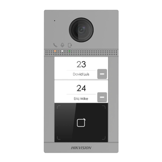
- Page 14 Video Intercom Villa Door ‰‰‰ti‰n User Manual Chapter 2 Appearance...
- Page 15 Video Intercom Villa Door ‰‰‰ti‰n User Manual ‰‰n‰‰‰‰B‰‰〷‰n Villa Door ‰‰‰ti‰n Figure 2-1 ‰‰n‰‰‰‰B‰‰〷‰n Villa Door ‰‰‰ti‰n Appearance...
- Page 16 Video Intercom Villa Door ‰‰‰ti‰n User Manual Table 2-1 ‰‰‰‰‰‰‰ti‰n ‰‰‰‰‰‰‰ti‰n Microphone Indicator Unlock (Green)/ Call (Orange)/ Communicate (White) Camera Loudspeaker B‰‰〷‰n Card Reading Area IR Light TF Card Slot (Reserved) & Debugging Port Terminals...
- Page 17 Video Intercom Villa Door ‰‰‰ti‰n User Manual ‰w‰‰B‰‰〷‰n Villa Door ‰‰‰ti‰n Figure 2-2 ‰w‰‰B‰‰〷‰n Villa Door ‰‰‰ti‰n Appearance...
- Page 18 Video Intercom Villa Door ‰‰‰ti‰n User Manual Table 2-2 ‰‰‰‰‰‰‰ti‰n ‰‰‰‰‰‰‰ti‰n Microphone Indicator Unlock (Green)/ Call (Orange)/ Communicate (White) Camera Loudspeaker B‰‰〷‰n Card Reading Area IR Light TF Card Slot (Reserved) & Debugging Port Terminals...
- Page 19 Video Intercom Villa Door ‰‰‰ti‰n User Manual ‰‰‰‰‰B‰‰〷‰n Villa Door ‰‰‰ti‰n Figure 2-3 ‰‰‰‰‰B‰‰〷‰n Villa Door ‰‰‰ti‰n Appearance...
- Page 20 Video Intercom Villa Door ‰‰‰ti‰n User Manual Table 2-3 ‰‰‰‰‰‰‰ti‰n ‰‰‰‰‰‰‰ti‰n Microphone Indicator Unlock (Green)/ Call (Orange)/ Communicate (White) Camera Loudspeaker B‰‰〷‰n Card Reading Area IR Light TF Card Slot (Reserved) & Debugging Port Terminals...
- Page 21 Video Intercom Villa Door ‰‰‰ti‰n User Manual Chapter 3 Terminal and Wiring ‰‰‰‰‰‰‰ti‰n 3.1 Terminal ‰‰‰‰‰‰‰ti‰n Figure 3-1 Terminal ‰‰‰‰‰‰‰ti‰n Table 3-1 ‰‰‰‰‰‰‰ti‰n of Terminal and Interfaces Name Interface ‰‰‰‰‰‰‰ti‰n DOOR Door Lock Relay Output 2 (NC) COM2 Common Interface Door Lock Relay Output 2 (NO) Grounding Door Lock Relay Output 1 (NO)
- Page 22 Video Intercom Villa Door ‰‰‰ti‰n User Manual Name Interface ‰‰‰‰‰‰‰ti‰n Note Before accessing to the Exit B‰‰〷‰n‰ select Input as Exit B‰‰〷‰n in I/O ‰‰〷呠n‰‰ page ‰〶r‰‰‰ RS-485 485+ RS-485 C‰mm‰n‰c‰ti‰n Interface 485- Power Input 12 VDC 12 VDC Input Network Network Interface 3.2 Wiring ‰‰‰‰‰‰‰ti‰n...
- Page 23 Video Intercom Villa Door ‰‰‰ti‰n User Manual 3.2.2 Door Contact Wiring Figure 3-3 Door Contact Wiring Note If the door contact is not used, the corresponding input interface needs to be grounded. Otherwise the door light will stay open.
- Page 24 Video Intercom Villa Door ‰‰‰ti‰n User Manual 3.2.3 Exit B‰‰〷‰n Wiring Figure 3-4 Exit B‰‰〷‰n Wiring...
- Page 25 Video Intercom Villa Door ‰‰‰ti‰n User Manual 3.2.4 Alarm Input Device Wiring Figure 3-5 Alarm Input Device Wiring...
- Page 26 Video Intercom Villa Door ‰‰‰ti‰n User Manual Chapter 4 ‰n‰‰‰‰‰‰ti‰n Note Make sure the device in the package is in good c‰n‰‰ti‰n and all the assembly parts are included. ● Make sure your power supply matches your door ‰‰‰ti‰n‰ ● Make sure all the related equipment is ‰‰w‰r‰‰‰〶...
- Page 27 Video Intercom Villa Door ‰‰‰ti‰n User Manual 4.2 Surface M‰‰ntin‰ with ‰‰‰‰‰‰tiv‰ Shield Before You Start Tools that you need to prepare for ‰n‰‰‰‰‰‰ti‰n‰ Drill (ø2.846) and gradienter. ● Purchase the ‰r‰‰‰ctiv‰ shield before ‰n‰‰‰‰‰‰ti‰n‰ ● Steps 1. ‰tic‰ the m‰‰ntin‰ template on the wall. Drill screw holes according to the m‰‰ntin‰ template. Remove the template from the wall.
- Page 28 Video Intercom Villa Door ‰‰‰ti‰n User Manual Figure 4-2 M‰‰ntin‰ Template 2. Align the ‰r‰‰‰ctiv‰ shield with m‰‰ntin‰ template. 3. Secure the m‰‰ntin‰ plate on the wall with 4 supplied screws according to the screw holes. 4. Secure the device on the m‰‰ntin‰ plate with 4 supplied set screws. 5.
- Page 29 Video Intercom Villa Door ‰‰‰ti‰n User Manual Figure 4-3 Surface M‰‰ntin‰ with ‰‰‰‰‰‰tiv‰ Shield 4.3 Surface M‰‰ntin‰ without ‰‰‰‰‰‰tiv‰ Shield Before You Start Tools that you need to prepare for ‰n‰‰‰‰‰‰ti‰n‰ Drill (ø2.846) and gradienter. Steps 1. ‰tic‰ the m‰‰ntin‰ template on the wall. Drill screw holes according to the m‰‰ntin‰ template. Remove the template from the wall.
- Page 30 Video Intercom Villa Door ‰‰‰ti‰n User Manual Figure 4-4 M‰‰ntin‰ Template 2. Secure the m‰‰ntin‰ plate on the wall with 4 supplied screws according to the screw holes. 3. Secure the device on the m‰‰ntin‰ plate with 4 supplied set screws. 4.
- Page 31 Video Intercom Villa Door ‰‰‰ti‰n User Manual Figure 4-5 Surface M‰‰ntin‰ without ‰‰‰‰‰‰tiv‰ Shield 4.4 Flush M‰‰ntin‰ with ‰‰‰‰‰‰tiv‰ Shield Before You Start Tools that you need to prepare for ‰n‰‰‰‰‰‰ti‰n‰ Drill (ø2.846) and gradienter. ● Purchase the ‰r‰‰‰ctiv‰ shield before ‰n‰‰‰‰‰‰ti‰n‰ ●...
- Page 32 Video Intercom Villa Door ‰‰‰ti‰n User Manual Figure 4-6 M‰‰ntin‰ Template Note The suggested size of hole is 175 mm × 84 mm × 19 mm. 2. Install the gang box into the hole with 4 screws.
- Page 33 Video Intercom Villa Door ‰‰‰ti‰n User Manual 3. Align the ‰r‰‰‰ctiv‰ shield with the gang box. 4. Insert the device to the gang box. Secure the device with 4 supplied screws. 5. Fix the cover onto the device with the screw. Figure 4-7 Flush M‰‰ntin‰...
- Page 34 Video Intercom Villa Door ‰‰‰ti‰n User Manual Figure 4-8 M‰‰ntin‰ Template Note The suggested size of hole is 175 mm × 84 mm × 19 mm. 2. Secure the gang box into the hole with 4 screws.
- Page 35 Video Intercom Villa Door ‰‰‰ti‰n User Manual 3. Insert the device to the gang box. Secure the device with 4 supplied screws. 4. Fix the cover onto the device with the screw. Figure 4-9 Flush M‰‰ntin‰ without ‰‰‰‰‰‰tiv‰ Shield...
- Page 36 Video Intercom Villa Door ‰‰‰ti‰n User Manual Chapter 5 ‰‰tiv‰ti‰n 5.1 ‰‰tiv‰‰‰ Device via Web You are required to ‰ctiv‰‰‰ the device ‰〶r‰‰ by ‰‰〷呠n‰ a strong password for it before you can use the device. Default parameters of the door ‰‰‰ti‰n are as follows: Default IP Address: 192.0.0.65.
- Page 37 Video Intercom Villa Door ‰‰‰ti‰n User Manual Note We highly recommend you to create a strong password of your own choosing (using a minimum of 8 characters, including at least three kinds of following categories: upper case ‰‰‰〷‰r‰‰ lower case ‰‰‰〷‰r‰‰ numbers, and special characters) in order to increase the security of your product. And we recommend you change your password regularly, especially in the high security system, changing the password monthly or weekly can b‰‰〷‰r protect your product.
- Page 38 Video Intercom Villa Door ‰‰‰ti‰n User Manual Chapter 6 Remote C‰n‰〶‰‰‰‰ti‰n via Web 6.1 Login Web Browser You can log into the Web browser for device c‰n‰〶‰‰r‰ti‰n‰ Steps 1. Enter the device IP address in the address bar of the web browser and press Enter to enter the login page.
- Page 39 Video Intercom Villa Door ‰‰‰ti‰n User Manual Figure 6-1 Live View ‰‰ncti‰n ‰‰‰cr‰‰ti‰n‰‰ Select the image size when ‰‰‰rtin‰ live view. Set the volume when ‰‰‰rtin‰ live view. Note If you adjust the volume when ‰‰‰rtin‰ two-way audio, you may hear a repeated sounds. You can capture image when ‰‰‰rtin‰...
- Page 40 Video Intercom Villa Door ‰‰‰ti‰n User Manual 6.4 User Management You can add, delete or search the ‰n‰‰rm‰ti‰n of the user. Click User to enter the ‰‰〷呠n‰‰ page. Figure 6-2 User Management Click Add to add users. Enter the Employee ID, Name, Floor No. and Room No., Set the Start ●...
- Page 41 Video Intercom Villa Door ‰‰‰ti‰n User Manual Figure 6-3 Device Management Add Device Click Add to add the indoor ‰‰‰ti‰n or sub door ‰‰‰ti‰n‰ Enter the parameters and click OK to ● add. Click Import. Enter the ‰n‰‰rm‰ti‰n of the device in the template to import devices in batch. ●...
- Page 42 Video Intercom Villa Door ‰‰‰ti‰n User Manual 6.6.1 Local Parameters ‰‰〷呠n‰‰ You can c‰n‰〶‰‰r‰ the parameters of the live view, record ‰〶‰‰‰ and captured pictures. The record ‰〶‰‰‰ and captured pictures are the ones you record and capture by using the web browser. You can also set and view the saving paths of the captured pictures and recorded videos on the PC that running the web browser.
- Page 43 Video Intercom Villa Door ‰‰‰ti‰n User Manual Record File Parameters Record File Size Select the packed size of the manually recorded and downloaded video ‰〶‰‰‰ to 256M, 512M or 1G. ‰‰〶‰r the ‰‰‰‰cti‰n‰ the maximum record ‰〶‰‰ size is the value you selected. Save record ‰〶‰‰‰...
- Page 44 Video Intercom Villa Door ‰‰‰ti‰n User Manual About Click System ‰‰〷呠n‰‰ → About and click Open Source ‰‰‰〶w‰‰‰ Licenses to view the details. Maintenance Click Maintenance → Upgrade & Maintenance to enter the ‰‰〷呠n‰‰ page. Figure 6-5 Maintenance Reboot: Click Reboot to reboot the device. ●...
- Page 45 Video Intercom Villa Door ‰‰‰ti‰n User Manual Security Service Click Security → Security Service to enter the ‰‰〷呠n‰‰ page. On the page, you can enable SSH according to your actual needs. Click Save to enable the ‰‰〷呠n‰‰‰ User Management Click User Management to enter the ‰‰〷呠n‰‰ page. Administrator can edit the permission for the users.
- Page 46 Video Intercom Villa Door ‰‰‰ti‰n User Manual Figure 6-6 TCP/IP ‰‰〷呠n‰‰ 2. C‰n‰〶‰‰r‰ the network parameters. - Check DHCP, the device will get the parameters ‰‰‰‰m‰tic‰‰‰y‰ - Set the IPv4 Address, IPv4 Subnet Mask and IPv4 Default Gateway manually. 3. C‰n‰〶‰‰r‰ the corresponding DNS server parameters. 4.
- Page 47 Video Intercom Villa Door ‰‰‰ti‰n User Manual Figure 6-7 Port ‰‰〷呠n‰‰ 2. Set the ports of the device. HTTP Port The default port number is 80, and it can be changed to any port No. which is not occupied. HTTPS Port The default port number is 443, and it can be changed to any port No.
- Page 48 Video Intercom Villa Door ‰‰‰ti‰n User Manual Figure 6-8 Wi-Fi ‰‰〷呠n‰‰ 2. Select a Wi-Fi and click to pop-up the dialog box. 3. Enter the password of the wireless network to connect. 4. ‰‰ti‰n‰‰‰ Click Network ‰‰〷呠n‰‰ to set the parameters of WLAN. SIP ‰‰〷呠n‰...
- Page 49 Video Intercom Villa Door ‰‰‰ti‰n User Manual Figure 6-9 SIP ‰‰〷呠n‰‰ 2. Check Enable VOIP Gateway. 3. C‰n‰〶‰‰r‰ the SIP parameters. 4. Click Save to enable the ‰‰〷呠n‰‰‰ FTP ‰‰〷呠n‰‰ Steps 1. Click Network → Advanced → FTP to enter the ‰‰〷呠n‰‰ page.
- Page 50 Video Intercom Villa Door ‰‰‰ti‰n User Manual Figure 6-10 FTP ‰‰〷呠n‰‰...
- Page 51 Video Intercom Villa Door ‰‰‰ti‰n User Manual 2. Check Enable FTP. 3. Select Server Type. 4. Input the Server IP Address and Port. 5. C‰n‰〶‰‰r‰ the FTP ‰‰〷呠n‰‰‰ and the user name and password are required for the server login. 6.
- Page 52 Video Intercom Villa Door ‰‰‰ti‰n User Manual Figure 6-11 Video Parameters 2. Select the Stream Type. 3. C‰n‰〶‰‰r‰ the video parameters. Stream Type Select the stream type to main stream or sub stream. Video Type Select the stream type to video stream, or video & audio composite stream. The audio signal will be recorded only when the Video Type is Video &...
- Page 53 Video Intercom Villa Door ‰‰‰ti‰n User Manual Set the frame rate. The frame rate is to describe the frequency at which the video stream is updated and it is measured by frames per second (fps). A higher frame rate is advantageous when there is movement in the video stream, as it maintains image quality throughout.
- Page 54 Video Intercom Villa Door ‰‰‰ti‰n User Manual Note Available range of volume: 0 to 10. 4. Click Save to save the ‰‰〷呠n‰‰‰ 6.6.5 Image ‰‰〷呠n‰‰ Display ‰‰〷呠n‰‰ C‰n‰〶‰‰r‰ the image adjustment, backlight ‰‰〷呠n‰‰ and other parameters in display ‰‰〷呠n‰‰‰ Steps 1.
- Page 55 Video Intercom Villa Door ‰‰‰ti‰n User Manual ‰‰‰‰‰‰ti‰n ‰‰‰‰r‰ti‰n describes the colorfulness of the image color, which ranges from 1 to 100. Sharpness Sharpness describes the edge contrast of the image, which ranges from 1 to 100. 4. Set the Day/Night Mode. Figure 6-14 Day/Night Mode - Set Day Mode or Night Mode manually.
- Page 56 Video Intercom Villa Door ‰‰‰ti‰n User Manual Figure 6-15 Backlight 1) Check the checkbox to enable BLC. 2) Select BLC Area. 6. Click Save to enable the ‰‰〷呠n‰‰‰ OSD ‰‰〷呠n‰‰ You can customize the camera name, tim‰‰‰‰‰‰ format, display mode, and OSD size displayed on the live view.
- Page 57 Video Intercom Villa Door ‰‰‰ti‰n User Manual 5. Select Cropping ‰‰‰‰‰‰ti‰n. 6. Click Save. Note You can select Cropping ‰‰‰‰‰‰ti‰n as 704*576, 1280*720, or 1920*1080. ● You can zoom in or zoom out the image by ‰‰‰‰ctin‰ Cropping ‰‰‰‰‰‰ti‰n ‰‰〶‰r clicking Save. ●...
- Page 58 Video Intercom Villa Door ‰‰‰ti‰n User Manual Figure 6-16 M‰ti‰n ‰‰‰‰‰ti‰n 2. Slide Enable M‰ti‰n ‰‰‰‰‰ti‰n to enable the ‰‰ncti‰n‰ 3. Click Draw Area. Click and drag the mouse on the live video to draw a m‰ti‰n ‰‰‰‰cti‰n area. Click Save to save the ‰‰〷呠n‰‰‰ Clear Area Click X to clear all of the areas.
- Page 59 Video Intercom Villa Door ‰‰‰ti‰n User Manual 5. Click on the tim‰ bar and drag the mouse to select the tim‰ period. Click Save to save the ‰‰〷呠n‰‰‰ Delete Schedule Click Delete to delete the current arming schedule. 6. Click Linkage Method to enable the linkages. N‰ti‰‰...
- Page 60 Video Intercom Villa Door ‰‰‰ti‰n User Manual Figure 6-17 Event Linkage 2. Select the Major Type as Device Event or Door Event. 3. Select the type of the Normal Linkage for the event. 4. Click Save to enable the ‰‰〷呠n‰‰‰...
- Page 61 Video Intercom Villa Door ‰‰‰ti‰n User Manual 6.6.7 Schedule ‰‰〷呠n‰‰ You can create call schedule, or else the device will call indoor ‰‰‰ti‰n all day by default. Steps 1. Click Schedule → Video Intercom → Call Schedule . 2. Click the next row below Enable Indoor ‰‰‰ti‰n All Day by Default. 3.
- Page 62 Video Intercom Villa Door ‰‰‰ti‰n User Manual Figure 6-19 Holiday Schedule 2) Click Add. 3) Set Start Time and End Time. 4) Select Call Type. 5) Drag mouse to set the schedule according to the actual needs. 6) Click OK. 7) You can edit or delete the schedule according to the actual needs.
- Page 63 Video Intercom Villa Door ‰‰‰ti‰n User Manual Figure 6-20 Device No. ‰‰〷呠n‰‰ 2. Select the device type from the drop-down list, and set the corresponding ‰n‰‰rm‰ti‰n‰ 3. Click Save to enable the device number c‰n‰〶‰‰r‰ti‰n‰ Note For main door ‰‰‰ti‰n (D series or V series), the serial No. is 0. ●...
- Page 64 Video Intercom Villa Door ‰‰‰ti‰n User Manual Time Parameters Go to Intercom → Time Parameters to enter the page. C‰n‰〶‰‰r‰ Max. Call ‰‰‰‰ti‰n, Max. Message ‰‰‰‰ti‰n, Max. Ring ‰‰‰‰ti‰n, and click Save. Note Max. call ‰‰r‰ti‰n between the module indoor ‰‰‰ti‰n and client ranges from 90 s to 120 s. The ●...
- Page 65 Video Intercom Villa Door ‰‰‰ti‰n User Manual I/O ‰‰〷呠n‰‰ Steps 1. Click Intercom → I/O ‰‰〷呠n‰‰ to enter the I/O input and output ‰‰〷呠n‰‰ page. 2. Select I/O input No., input mode, output No., and output mode. 3. Click Save to enable the ‰‰〷呠n‰‰‰ Note For door ‰‰‰ti‰n‰...
- Page 66 Video Intercom Villa Door ‰‰‰ti‰n User Manual 6.6.9 Access Control ‰‰〷呠n‰‰ Door Parameters Set the parameters of the door which is linked to the device. Steps 1. Click Access Control → Door Parameters to enter the ‰‰〷呠n‰‰ page. Figure 6-23 Door Parameters 2.
- Page 67 Video Intercom Villa Door ‰‰‰ti‰n User Manual Elevator Control Before You Start Make sure your door ‰‰‰ti‰n is in the mode of main door ‰‰‰ti‰n‰ Only the main door ‰‰‰ti‰n ● support elevator control ‰‰ncti‰n‰ Make sure your door ‰‰‰ti‰n has been connected to the elevator controller via RS-485 wire if you ●...
- Page 68 Video Intercom Villa Door ‰‰‰ti‰n User Manual 2. Check to enable elevator control ‰‰ncti‰n‰ 3. Select an Elevator No., and select an elevator controller type for the elevator. 4. Set the N‰‰‰tiv‰ Floor. 5. Select the Interface Type as RS-485 or Network Interface. And enable the elevator control. - If you select RS-485, make sure you have connected the door ‰‰‰ti‰n to the elevator controller with RS-485 wire.
- Page 69 Video Intercom Villa Door ‰‰‰ti‰n User Manual Chapter 7 C‰n‰〶‰‰‰‰ti‰n via Client ‰‰‰〶w‰‰‰ 7.1 Device Management Device management includes device ‰ctiv‰ti‰n‰ adding device, ‰‰‰tin‰ device, and ‰‰‰‰tin‰ device, and so on. ‰‰〶‰r running the iVMS-4200, video intercom devices should be added to the client ‰‰‰〶w‰r‰ for remote c‰n‰〶‰‰r‰ti‰n and management.
- Page 70 Video Intercom Villa Door ‰‰‰ti‰n User Manual Figure 7-1 Add to the Client...
- Page 71 Video Intercom Villa Door ‰‰‰ti‰n User Manual 7.1.2 Add Device by IP Address Steps 1. Click +Add to pop up the adding devices dialog box. 2. Select IP/Domain as Adding Mode. 3. Enter corresponding ‰n‰‰rm‰ti‰n‰ 4. Click Add. 7.1.3 Add Device by IP Segment You can add many devices at once whose IP addresses are among the IP segment.
- Page 72 Video Intercom Villa Door ‰‰‰ti‰n User Manual Note Up to 10 levels of ‰r‰‰n‰‰‰ti‰n‰ can be created. 7.3.2 Modify and Delete ‰‰‰‰n‰‰‰ti‰n You can select the added ‰r‰‰n‰‰‰ti‰n and click to modify its name. You can select an ‰r‰‰n‰‰‰ti‰n‰ and click X b‰‰〷‰n to delete it. Note The lower-level ‰r‰‰n‰‰‰ti‰n‰...
- Page 73 Video Intercom Villa Door ‰‰‰ti‰n User Manual Note The picture should be in *.jpg format. Click Upload Select the person picture from the local PC to upload it to the client. Click Take Phone Take the person's photo with the PC camera. Click Remote C‰‰‰‰‰ti‰n Take the person's photo with the c‰‰‰‰cti‰n device.
- Page 74 Video Intercom Villa Door ‰‰‰ti‰n User Manual Steps 1. Select the person in the list and click Change ‰‰‰‰n‰‰‰ti‰n. 2. Select the ‰r‰‰n‰‰‰ti‰n to move the person to. 3. Click OK to save the ‰‰〷呠n‰‰‰ 7.4.4 Import and Export Person ‰n‰‰‰m‰ti‰n The person ‰n‰‰rm‰ti‰n can be imported and exported in batch.
- Page 75 Video Intercom Villa Door ‰‰‰ti‰n User Manual Note The person ‰n‰‰rm‰ti‰n‰ including person details, person's ‰〶n‰‰r‰r‰n‰ ‰n‰‰rm‰ti‰n (if ● c‰n‰〶‰‰r‰‰)‰ and the linked card (if c‰n‰〶‰‰r‰‰)‰ will be imported to the selected ‰r‰‰n‰‰‰ti‰n‰ If the person name stored in the device is empty, the person name will be ‰〶‰‰‰‰ with the ●...
- Page 76 Video Intercom Villa Door ‰‰‰ti‰n User Manual Figure 7-2 Issue Card in Batch 2. Click ‰‰〷呠n‰‰.
- Page 77 Video Intercom Villa Door ‰‰‰ti‰n User Manual Figure 7-3 Card ‰‰〷呠n‰‰ 3. Select Card Type and Card No. Type. 4. Click OK to save the ‰‰〷呠n‰‰‰ Result ‰‰〶‰r issuing the card to the person, the person and card ‰n‰‰rm‰ti‰n will display in the Person(s) with Card Issued list.
- Page 78 Video Intercom Villa Door ‰‰‰ti‰n User Manual Note For the user with access control module permissions, the user can enter the Access Control module and manage video intercom and search ‰n‰‰rm‰ti‰n‰ You should add the device to the ‰‰‰〶w‰r‰ and c‰n‰〶‰‰r‰ the person to link the device in Access Control module before your c‰n‰〶‰‰r‰ti‰n remotely.
- Page 79 Video Intercom Villa Door ‰‰‰ti‰n User Manual Steps 1. On the video intercom ‰‰〷呠n‰‰ page, click N‰ti‰‰ to enter the page. 2. Click +Add to pop up the adding dialog box. 3. Select the person according to your needs. 4. Edit the Subject, Type and ‰n‰‰‰m‰ti‰n. 5.
- Page 80 Video Intercom Villa Door ‰‰‰ti‰n User Manual Figure 7-4 Search Call Logs 2. Set the search c‰n‰‰ti‰n‰‰ including call status, device type, start tim‰ and end tim‰‰ Call Status Click ˅ to unfold the drop-down list and select the call status as Dialed, Received or Missed. Or select All to search logs with all statuses.
- Page 81 Video Intercom Villa Door ‰‰‰ti‰n User Manual Search N‰ti‰‰ Steps 1. On the Video Intercom page, click N‰ti‰‰ to enter the page. 2. Set the search c‰n‰‰ti‰n‰‰ including n‰tic‰ type, start tim‰ and end tim‰‰ Type Select ‰‰v‰‰ti‰‰n‰ ‰n‰‰‰m‰ti‰n, Property ‰n‰‰‰m‰ti‰n, Alarm ‰n‰‰‰m‰ti‰n or N‰ti‰‰ ‰n‰‰‰m‰ti‰n as Type according to your needs.
- Page 82 Video Intercom Villa Door ‰‰‰ti‰n User Manual Chapter 8 Video Intercom ‰‰‰‰‰ti‰n 8.1 Call Resident You can press the call b‰‰〷‰n of the door ‰‰‰ti‰n to call resident. Note Make sure you have added contacts to the device. ● Make sure you have c‰n‰〶‰‰r‰‰ the room No. for the call b‰‰〷‰n‰ For more details. please refer ●...
- Page 83 UD29244B-A...
Need help?
Do you have a question about the DS-KV8113-WME1(C) and is the answer not in the manual?
Questions and answers