Table of Contents
Advertisement
Advertisement
Table of Contents

Related Manuals for HIKVISION DS-KV8102-1A


Summary of Contents for HIKVISION DS-KV8102-1A
- Page 1 Video Intercom Door Station (V Series) User Manual UD.6L0206D1033A01...
- Page 2 Trademarks and other Hikvision marks are the property of Hikvision and are registered trademarks or the subject of applications for the same by Hikvision and/or its affiliates. Other trademarks mentioned in this manual are the properties of their respective owners. No right of license is given to use such trademarks without express permission.
- Page 3 FOR LOSS OF BUSINESS PROFITS, BUSINESS INTERRUPTION, SECURITY BREACHES, OR LOSS OF DATA OR DOCUMENTATION, IN CONNECTION WITH THE USE OF OR RELIANCE ON THIS MANUAL, EVEN IF HIKVISION HAS BEEN ADVISED OF THE POSSIBILITY OF SUCH DAMAGES. SOME JURISDICTIONS DO NOT ALLOW THE EXCLUSION OR LIMITATION OF LIABILITY OR CERTAIN DAMAGES, SO SOME OR ALL OF THE ABOVE EXCLUSIONS OR LIMITATIONS MAY NOT APPLY TO YOU.
-
Page 4: Regulatory Information
Video Intercom Door Station·User Manual Regulatory Information FCC Information compliance: This equipment has been tested and found to comply with the limits for a digital device, pursuant to part 15 of the FCC Rules. These limits are designed to provide reasonable protection against harmful interference when the equipment is operated in a commercial environment. - Page 5 Video Intercom Door Station·User Manual Safety Instruction These instructions are intended to ensure that user can use the product correctly to avoid danger or property loss. The precaution measure is divided into Warnings and Cautions: Warnings: Neglecting any of the warnings may cause serious injury or death. Cautions: Neglecting any of the cautions may cause injury or equipment damage.
- Page 6 Video Intercom Door Station·User Manual Exposing the equipment to direct sun light, low ventilation or heat source such as heater or radiator is forbidden (ignorance can cause fire danger). Do not aim the device at the sun or extra bright places. A blooming or smear may occur otherwise (which is not a malfunction however), and affecting the endurance of sensor at the same time.
-
Page 7: Table Of Contents
Video Intercom Door Station·User Manual Table of Contents 1 Overview ...................... 1 1.1 Introduction ......................1 1.2 Main Features ......................1 2 Appearance ....................2 2.1 Appearance of Door Station (DS-KV8X02-1A) ............2 2.2 Appearance of Door Station (DS-KV8102-XC) ............3 3 Typical Application .................. - Page 8 Video Intercom Door Station·User Manual 8.4 Picture Storage ...................... 37 8.5 Group Management ....................37 8.5.1 Assigning Devices to Group ................37 8.5.2 Card Management ..................41 8.6 Notice Management ....................48 8.6.1 Query Unlocking Log ..................48 8.7 Device Arming Control ................... 48 9 Basic Operation ..................
-
Page 9: Overview
Video Intercom Door Station·User Manual 1 Overview 1.1 Introduction The video intercom system can realize functions such as video intercom, resident-to- resident video call, live view of HD video, access control, one-card system, elevator linkage, zone alarm, public notice and visitor messages to form a complete smart community video intercom solution. -
Page 10: Appearance
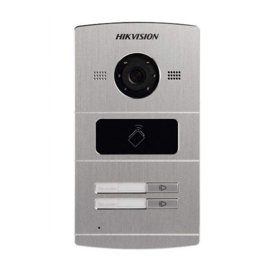
2 Appearance 2.1 Appearance of Door Station (DS-KV8X02-1A) Figure 2-1 Appearance of Door Station Description of Door Station Models Description Low Illumination Supplement Light Built-in Camera Swiping-card Area DS-KV8102-1A Calling Button DS-KV8202-1A DS-KV8402-1A Loudspeaker Room Number (Customized) Microphone Tamper-proof Button... -
Page 11: Appearance Of Door Station (Ds-Kv8102-Xc)
Video Intercom Door Station·User Manual 2.2 Appearance of Door Station (DS-KV8102-XC) Figure 2-2 Appearance of Door Station Description of Door Station Models Description Microphone Low Illumination Supplement Light DS-KV8102-1C Built-in Camera DS-KV8102-2C Swiping-card Area Calling Button Loudspeaker... -
Page 12: Typical Application
Video Intercom Door Station·User Manual 3 Typical Application 3.1 Typical Application of Door Station (DS-KV8X02-1A) Please refer to the following figure for typical application of DS-KV8102-1A/ DS-KV8202- 1A/ DS-KV8402-1A door station. Indoor Stations Resident 2 Resident 1 Door Station Connect to the LAN of... - Page 13 Video Intercom Door Station·User Manual Indoor Station Resident Door Station Connect to the LAN of Community via Optical Fiber Network Cable Optical Fiber Figure 3-2 Typical Application (1) Indoor Stations Doorphones Resident 1 Resident 2 Resident 1 Resident 2 Resident 1 Resident 2 Resident 1 Resident 2...
-
Page 14: Terminals And Interfaces Of Wiring
Video Intercom Door Station·User Manual 4 Terminals and Interfaces of Wiring Please refer to the following figure for terminals and interfaces of door station. ①-⑤ ⑥-⑦ ⑧-⑨ ⑬ ⑩-⑫ Figure 4-1 Terminals and Interfaces Table 4-1 Descriptions of Terminals and Interfaces Terminals and Interfaces Name Description... -
Page 15: Installation And Wiring
To install the door station onto the wall, you are required to utilize a matched gang box. 5.1.1 Gang Box for DS-KV8X02-1A Model Please refer to the following figures for the dimensions of gang box for DS-KV8102-1A/ DS-KV8202-1A/ DS-KV8402-1A door station. -
Page 16: Wall Mounting With Gang Box Of Ds-Kv8X02-1A Model
Video Intercom Door Station·User Manual The dimensions above are theoretical. The actual size can be slightly different from the theoretical dimension. 5.1.2 Wall Mounting with Gang Box of DS-KV8X02-1A Model Steps: 1. Take the gang box and screws from the packing box. 2. -
Page 17: Installation Of Ds-Kv8102-Xc Model
Video Intercom Door Station·User Manual 5. After inserting the door station into the gang box, pull the device downwards to hook the door station with the gang box. 6. Secure the door station by inserting the fixing screw according to the direction of the arrow of the figure below. -
Page 18: Wall Mounting With Gang Box Of Ds-Kv8102-Xc Model
Video Intercom Door Station·User Manual Hollow Area 41.48 72.7 Figure 5-5 Dimensions of Installation Plate The dimension of gang box for model DS-KV8102-1C/ DS-KV8102-2C door station is: 75 (width) × 75 (length) × 50 (depth) mm. The dimensions above are theoretical. The actual size can be slightly different from the theoretical dimension. - Page 19 Video Intercom Door Station·User Manual 4. Attach the installation plate to the gang box and align the screw holes of the installation plate with the screw holes of the gang box. 5. Insert 2 PA4 screws and a KA4 screw into the screw holes to fix the installation plate onto the gang box.(The KA4 screw is optional.) PA4 Screws KA4 Screw...
-
Page 20: Wiring
Video Intercom Door Station·User Manual 7. Secure the door station by inserting the fixing screw according to the direction of the arrow of the figure below. Figure 5-9 Secure the Door Station 5.3 Wiring 5.3.1 Door Lock Wiring Please refer to the following figure for door lock wiring. Magnetic Lock / Electric Electric Bolt... -
Page 21: Door Magnetic Wiring
Video Intercom Door Station·User Manual Terminal DR_NC/DR_COM is set as default for accessing magnetic lock/electric bolt; terminal DR_NO/DR_COM is set as default for accessing electric strike. To connect electric lock in terminal DR_NC/DR_COM/DR_NO, it is required to set the output of terminal DR_NC/DR_COM/DR_NO to be electric lock with video intercom configuring tool software or iVMS-4200 client software. -
Page 22: Wiring Of Alarm Device Input
Video Intercom Door Station·User Manual Figure 5-12 Door Switch Wiring To connect door switch button in terminal ALARM_n(ALARM_1~ALARM_4) /ALARM_GND, it is required to set the input of terminal ALARM_n (ALARM_1~ALARM_4)/ALARM_GND to be door switch button with video intercom configuring tool software or iVMS-4200 client software. 5.3.4 Wiring of Alarm Device Input Please refer to the following figure for NO detector wiring. -
Page 23: Before You Start
Video Intercom Door Station·User Manual To connect other alarm devices in terminal ALARM_n(ALARM_1~ALARM_4) /ALARM_GND, it is required to set the input of terminal ALARM_n (ALARM_1~ALARM_4)/ALARM_GND to be custom with video intercom configuring tool software or iVMS-4200 client software. 6 Before You Start To access to the device via internet with Batch Configuration Tool, iVMS- 4200 or other client software, you should firstly activate the device and set the device password. -
Page 24: Adding Device
Video Intercom Door Station·User Manual 2. Create a password and input the password into the password field. STRONG PASSWORD RECOMMENDED– We highly recommend you create a strong password of your own choosing (Using a minimum of 8 characters, including at least three of the following categories: upper case letters, lower case letters, numbers, and special characters.) in order to increase the security of your product. - Page 25 Video Intercom Door Station·User Manual Figure 7-2 Main Interface of Batch Configuration Software 2. On the Batch Configuration interface, the active online devices within your subnet display in the Online Devices list in the lower part of the interface. Figure 7-3 Online Devices Interface 3.
-
Page 26: Adding Device By Ip Address
Video Intercom Door Station·User Manual 4. Enter the user name and password, and click OK to save the settings. Only the devices that are successfully logged in will be added to the device list for configuration. 7.2.2 Adding Device by IP Address Click and the adding devices dialog box pops up. - Page 27 Video Intercom Door Station·User Manual Figure 7-6 Adding by IP Segment Click OK to search and add the devices whose IP addresses are within the range of the defined IP segment to the device list. Task 3: Add by Port No. Purpose: When you want to add multiple devices which access to the network via port mapping, you can simultaneously add them by this method.
- Page 28 Video Intercom Door Station·User Manual Click OK to search and add the devices of which port numbers are within the defined port No. range to the device list. The user name and password of the devices added by IP segment should be identical.
-
Page 29: Edit Network Parameters
Video Intercom Door Station·User Manual 7.3 Edit Network Parameters Purpose: You can edit the network parameters of online devices. Steps: 1. In the online devices area, the online devices of same segment are listed. Select the device to edit network parameters and click Edit NET Parameters. Figure 7-8 Edit NET Parameters 2. -
Page 30: System
Video Intercom Door Station·User Manual Figure 7-10 Remote Configuration 7.4.1 System Click on the remote configuration interface to display the device information: Device Information, General, Time, System Maintenance, User, RS485. Device Information Click to enter device basic information interface. You can view the device type, serial No. - Page 31 Video Intercom Door Station·User Manual Time Steps: 1. Click to enter the time setting interface. 2. Check the checkbox to enable NTP. Input the server address, NTP Port and synchronization interval. Click Apply to accomplish the time setting. Figure 7-13 Time Setting Interface The default Port No.
- Page 32 Video Intercom Door Station·User Manual Figure 7-14 System Maintenance Interface 2. Click and the system reboot dialog box pops up. Click Yes to reboot the system. 3. Click to restore the default parameters. 4. Click to restore all parameters of device and reset the device to inactive status.
- Page 33 Video Intercom Door Station·User Manual Figure 7-16 Importing Remote Configuration File Note 7. Click and the export file window pops up. Select the save path of remote configuration files and click Save to export the configuration file. Figure 7-17 Export Configuration File Window 8.
- Page 34 Video Intercom Door Station·User Manual User Purpose: You can edit the password to log in the device. Steps: 1. Click to enter the delete, add or edit user interface. Figure 7-19 Delete, Add or Edit User Interface 2. Select the user to edit and click to enter the user parameter interface.
-
Page 35: Video Intercom
Video Intercom Door Station·User Manual Figure 7-21 RS485 Parameters 7.4.2 Video Intercom Device Number Configuration Steps: 1. Click to enter the room number configuration interface. 2. Input the Room No. of indoor station. Figure 7-22 Configure Device Number (Door Station(V Series)) 3. - Page 36 Select doorphone as device type, and the serial No. is not necessary to configure. Please utilize the doorphone along with the main door station (V Series or D Series). The models DS-KV8102-1C, DS-KV8102-2C and DS-KV8102-1A are supported for using as doorphone and door station (V Series). The models DS-KV8202-1A, DS-KV8402-1A are supported for using only as door station (V Series).
- Page 37 Video Intercom Door Station·User Manual Figure 7-24 Change Password Interface Access Control and Elevator Click to enter the interface of setting parameters of access control and elevator. You can configure the parameters of access control and elevator. Figure 7-25 Interface of Access Control and Elevator Configuration IO In and Out Click to enter the IO in and out interface.
- Page 38 Video Intercom Door Station·User Manual There are 4 IO Input Terminals, Terminal 1~4 correspond to ALARM_1~ALARM_4 interfaces of door station. You can enable/disable IO In or set IO In as door magnetic or door switch by selecting from the dropdown list. ...
-
Page 39: Network
Video Intercom Door Station·User Manual 7.4.3 Network Local Network Configuration Steps: 1. Click to enter the local network configuration interface (the local network configuration interface is shown in the Figure 7-29). 2. Set the new IP Address, Subnet Mask, Gateway Address and Port No., and click Apply to accomplish the local network configuration setting. - Page 40 Video Intercom Door Station·User Manual Figure 7-30 Linked Devices Network Configuration Interface After adding master station IP Address, the linkage between indoor station and master station can be realized. After adding the door station IP Address, the video intercom between indoor stations of same building can be realized.
-
Page 41: Video Display
Video Intercom Door Station·User Manual Figure 7-31 FTP Parameters Interface 7.4.4 Video Display Steps: 1. Click menu to enter the video parameters interface (the video parameter interface is shown in the Figure 7-32). 2. Select the Camera No. and configure the format, hue, brightness, contrastness, saturation, sharpness and denoising or click to restore default settings. - Page 42 Video Intercom Door Station·User Manual Figure 7-32 Video Parameters Interface...
-
Page 43: Setting The Door Station Via Ivms-4200
Video Intercom Door Station·User Manual 8 Setting the Door Station via iVMS-4200 8.1 System Configuration After running the iVMS-4200, enter Control Panel -> Maintenance and Management -> System Configuration -> Video Intercom to configure the video intercom parameters accordingly. You can configure the ringtone, Max. ring duration, Max. speaking time with indoor station and Max. -
Page 44: Live View Of Device
Video Intercom Door Station·User Manual 8.3 Live View of Device Steps: 1. Enter the main view interface of iVMS-4200 client software to display the live view of door station (V Series). Figure 8-2 Live View of Door Station (V Series) 2. -
Page 45: Picture Storage
Video Intercom Door Station·User Manual Figure 8-3 Menu of Live View Interface 8.4 Picture Storage When the device is under armed status, it will auto capture after unlocking the door. If the storage server is installed together with iVMS-4200 client software, the captured picture will be uploaded to the storage server. - Page 46 Video Intercom Door Station·User Manual Figure 8-4 Group of Community 3. Select the group type and click to add group, input the corresponding information accordingly. 1). Select group type as Community and then Input the Project No., Community No., and Building No. to set the community structure, as shown in Figure 8-5 Add Building.
- Page 47 Video Intercom Door Station·User Manual Figure 8-6 Add Outer Door Station 3). Select organization type as Other and then input the group name. For example, you can set organizations as administrator, entrance guard and cleaning staff, etc., You can add group to Other Group and set different groups to assign cards to staff other than residents, such as administrator, security guard and cleaning staff, etc.,.
- Page 48 Video Intercom Door Station·User Manual 5. Check the checkboxes of devices and input the Room No. of indoor stations and door station No. to assign the devices to the community. 6. Click OK to save the setting. Figure 8-8 Assigned Residents 7.
-
Page 49: Card Management
Video Intercom Door Station·User Manual 8. To add person in other groups, you should select a sub group from Group Other and then click to add a person. Figure 8-10 Add Person 9. Input the name of the added person, and click OK to save the settings. 10. - Page 50 Video Intercom Door Station·User Manual Figure 8-11 Card Management Interface 2. Select Unauthorized Card and click Add Card to add unauthorized cards. Figure 8-12 Add Card Interface 3. Select adding mode to add cards in batch, add single card or with card reader. You can select card type as resident card or other card.
- Page 51 Video Intercom Door Station·User Manual Select Community on the left and the indoor stations of the community will be listed in the resident list. Figure 8-14 Issue Card Interface Click to assign cards to the indoor station. You can assign multiple cards to one indoor station.
- Page 52 Video Intercom Door Station·User Manual Figure 8-15 Card Selection Interface To Assign Other Cards: Select Other from the group list and the added persons of the community will be listed in the resident list. Figure 8-16 Issue Card Interface Click to assign cards to the organization.
- Page 53 Video Intercom Door Station·User Manual Figure 8-17 Card Selection Interface To Delete Cards: Click to enter the card issuing interface. Figure 8-18 Issue Card Interface Select the Community from groups to delete normal cards, and select Other from groups to delete other cards. To cancel certain cards or single card, click the button to enter the card selection interface.
- Page 54 Video Intercom Door Station·User Manual Figure 8-19 Card Selection Cancel the checkbox(es) of assigned cards and check the checkbox(es) of door station(s) to cancel the card(s). Click Issue Card to accomplish the operation. To Batch Import Unauthorized Cards: Click to enter the batch import interface, as shown in the figure below.
- Page 55 Video Intercom Door Station·User Manual Select the saving file path and click Save. After batch exporting the unauthorized cards, the excel will be generated in the saving directory. You can cancel card from single or certain door stations by cancelling the checkboxes from the device list.
-
Page 56: Notice Management
Video Intercom Door Station·User Manual 8.6 Notice Management 8.6.1 Query Unlocking Log Steps: 1. Click Query Unlocking Logs to enter query unlocking logs interface. 2. Select the unlocking type, device type, and set the start time and end time. Figure 8-21 Query Unlocking Logs 3. - Page 57 Video Intercom Door Station·User Manual Figure 8-22 Tool Menu Set the arming status of the device as armed, and the alarm information will be auto uploaded to the client software when alarm occurs. Figure 8-23 Device Arming Control Figure 8-24 Alarm Events...
- Page 58 Video Intercom Door Station·User Manual After adding the device to the client software, it will be armed automatically.
-
Page 59: Basic Operation
Here we take the figure of device DS-KV8402-1A as an example. For device DS-KV8102-1A, there is only 1 calling button. For device DS-KV8202-1A, there are 2 calling buttons. For device DS-KV8402-1A, there are 4 calling buttons. -
Page 60: Calling Resident (Device Ds-Kv8102-Xc)
Video Intercom Door Station·User Manual 9.1.2 Calling Resident (Device DS-KV8102-XC) You can call the resident by pressing the calling button. For device DS-KV8102-1C/2C, there is only 1 calling button. Calling Button Figure 9-2 Calling Button of DS-KV8102-XC Steps: 1. Press the calling button of the resident you need to call. 2. -
Page 61: Issuing Card
Video Intercom Door Station·User Manual 9.2 Issuing Card Purpose: You can assign the card to the door station or doorphone by issuing cards. You can issue cards by swiping the main card with the door station, or issue the card with iVMS-4200 client software. -
Page 62: Appendix
Door Lock Wiring (With Door Magnetic) RVV 4*1.0 Door Lock Wiring (Without Door Magnetic) RVV 2*1.0 Door Switch Button Wiring RVV 2*0.5 Specification Model DS-KV8102-1A/ DS-KV8202-1A/ DS-KV8402-1A Parameters System Parameters Processor High-performance Embedded SOC Processor Operation System Embedded Linux OS Video Parameters Camera CMOS Low Illumination 1.3 MP HD Colorful Camera... - Page 63 Video Intercom Door Station·User Manual Model DS-KV8102-1A/ DS-KV8202-1A/ DS-KV8402-1A Parameters Resolution 1280×720 Video Frame PAL: 25fps Audio Parameters Audio Input Built-in Omnidirectional Microphone Audio Output Built-in Loudspeaker Audio Compression G.711U Standard Audio Compression 64Kbps Rate Audio Quality Support Noise Suppression and Echo Cancellation...
- Page 64 Video Intercom Door Station·User Manual Model DS-KV8102-1A/ DS-KV8202-1A/ DS-KV8402-1A Parameters Power Supply 12V DC / Private POE Consumption ≤15W Working -40°C~+70°C (-40°F~158°F) Temperature Working Humidity 10%-90% IP Grade IP65 Dimension 182×100×32.5mm (7.17×3.94×1.28") Model DS-KV8102-1C/ DS-KV8102-2C Parameters System Parameters Processor High-performance Embedded SOC Processor...
- Page 65 Video Intercom Door Station·User Manual Model DS-KV8102-1C/ DS-KV8102-2C Parameters Door Switch Equip Door Switch Button to Open the Door NO/NC Supports NO/NC Status Setting Door Magnetic Detecting Door Magnetic Status Detection Network Parameters Ethernet 10M/100M Self-adaptive Ethernet Network Protocol TCP/IP, SNMP, SIP, RTSP Alarm Parameters Alarm Input Door Magnetic Alarm, Tamper Alarm...
- Page 66 Video Intercom Door Station·User Manual...
Need help?
Do you have a question about the DS-KV8102-1A and is the answer not in the manual?
Questions and answers