Table of Contents
Advertisement
Advertisement
Table of Contents

Related Manuals for HIKVISION DS-KV8202-IM


Summary of Contents for HIKVISION DS-KV8202-IM
- Page 1 Video Intercom Door Station (V Series) User Manual UD06175B...
- Page 2 Trademarks and other Hikvision marks are the property of Hikvision and are registered trademarks or the subject of applications for the same by Hikvision and/or its affiliates. Other trademarks mentioned in this manual are the properties of their respective owners. No right of license is given to use such trademarks without express permission.
- Page 3 FOR LOSS OF BUSINESS PROFITS, BUSINESS INTERRUPTION, SECURITY BREACHES, OR LOSS OF DATA OR DOCUMENTATION, IN CONNECTION WITH THE USE OF OR RELIANCE ON THIS MANUAL, EVEN IF HIKVISION HAS BEEN ADVISED OF THE POSSIBILITY OF SUCH DAMAGES. SOME JURISDICTIONS DO NOT ALLOW THE EXCLUSION OR LIMITATION OF LIABILITY OR CERTAIN DAMAGES, SO SOME OR ALL OF THE ABOVE EXCLUSIONS OR LIMITATIONS MAY NOT APPLY TO YOU.
- Page 4 Video Intercom Door Station·User Manual Regulatory Information FCC Information Please take attention that changes or modification not expressly approved by the party responsible for compliance could void the user’s authority to operate the equipment. FCC compliance: This equipment has been tested and found to comply with the limits for a Class B digital device, pursuant to part 15 of the FCC Rules.
- Page 5 Video Intercom Door Station·User Manual 2006/66/EC (battery directive): This product contains a battery that cannot be disposed of as unsorted municipal waste in the European Union. See the product documentation for specific battery information. The battery is marked with this symbol, which may include lettering to indicate cadmium (Cd), lead (Pb), or mercury (Hg).
- Page 6 Video Intercom Door Station·User Manual Safety Instruction These instructions are intended to ensure that user can use the product correctly to avoid danger or property loss. The precaution measure is divided into Warnings and Cautions: Warnings: Neglecting any of the warnings may cause serious injury or death. Cautions: Neglecting any of the cautions may cause injury or equipment damage.
- Page 7 Video Intercom Door Station·User Manual Model Manufacturer Standard DSA-12PFG-12 FUK 120100 Dee Van Electronics Co., Ltd. DSA-12PFG-12 FAU 120100 Dee Van Electronics Co., Ltd. Cautions Do not drop the device or subject it to physical shock, and do not expose it to high electromagnetism radiation.
-
Page 8: Table Of Contents
Video Intercom Door Station·User Manual Table of Contents 1 Overview ...................... 1 1.1 Introduction ......................1 1.2 Main Features ..................... 1 2 Appearance ....................2 2.1 Appearance of DS-KV8X02-IM ................2 2.2 Appearance of DS-KV8102-XP ................3 3 Typical Application ..................5 3.1 Typical Application of DS-KV8X02-IM .............. - Page 9 Video Intercom Door Station·User Manual 7.4.4 Video Display ....................34 7.5 Video Intercom Device Set-up Tool ..............35 7.5.1 Setting a Community Structure ..............36 7.5.2 Setting Main/Sub Door Station ..............36 7.6 Batch Upgrading ....................39 7.6.1 Adding Devices for Upgrading ..............39 7.6.2 Upgrading Devices ..................
-
Page 10: Overview
Video Intercom Door Station·User Manual 1 Overview 1.1 Introduction The door station (V series) can realize functions such as video intercom, access control, one-card system, zone alarm, and visitor messages to form a complete smart community video intercom solution. The door station (V series) is mainly applied in the villa, and can works as door station, outer door station, and doorphone. -
Page 11: Appearance
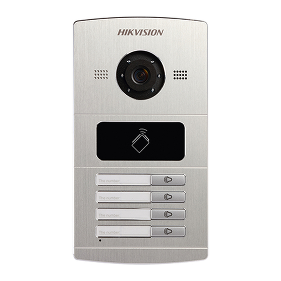
DS-KV8402-IM as an example. For device DS-KV8102-IM, there is only 1 call button. For device DS-KV8202-IM, there are 2 call buttons. For device DS-KV8402-IM, there are 4 call buttons. Figure 2-1 Appearance of DS-KV8402-IM... -
Page 12: Appearance Of Ds-Kv8102-Xp
Video Intercom Door Station·User Manual You need not customize the Room No. for device DS-KV8102-IM. Default settings of call button: when you press the call button, it calls the resident; and when you hold down the call button, it calls the center. ... - Page 13 Video Intercom Door Station·User Manual Default settings of call button: when you press the call button, it calls the resident; and when you hold down the call button, it calls the center. You can change the calling mode of the call button via Batch Configuration Tool or iVMS-4200 client software.
-
Page 14: Typical Application
Video Intercom Door Station·User Manual 3 Typical Application 3.1 Typical Application of DS-KV8X02-IM Please refer to the following figure for typical application of DS-KV8102-IM/ DS-KV8202-IM/ DS-KV8402-IM door station. House Wi-Fi/3G/4G Client Software Internet Indoor Indoor Wi-Fi Extension 2 Extension 2... -
Page 15: Typical Application Of Ds-Kv8102-Xp
Video Intercom Door Station·User Manual 3.2 Typical Application of DS-KV8102-XP Please refer to the following figures for typical applications of DS-KV8102-IP/ DS-KV8102-VP door station. House Client Software Indoor Indoor Extension 1 Video/Audio Extension 2 Master Station Distributor Wi-Fi/ 3G/4G Internet Wi-Fi Resident 1 Switch... -
Page 16: Terminal And Wiring
Video Intercom Door Station·User Manual 4 Terminal and Wiring 4.1 Terminal Description Please refer to the following figure for terminals and interfaces of door station. ①-⑤ ⑥-⑦ ⑧-⑨ ⑬ ⑩-⑫ Figure 4-1 Terminals and Interfaces Table 4-1 Descriptions of Terminals and Interfaces Terminals and Interfaces Name Color... -
Page 17: Wiring Description
Video Intercom Door Station·User Manual 4 I/O Input terminals (ALARM_1~ALARM_4) can be set as door magnetic input or door switch key input, and terminal ALARM_GND is for grounding connection. 1 I/O Output terminal can be enabled for controlling electric lock or disabled. 4.2 Wiring Description 4.2.1 Door Lock Wiring Figure 4-2 Door Lock Wiring... -
Page 18: Door Magnetic Wiring
Video Intercom Door Station·User Manual 4.2.2 Door Magnetic Wiring Figure 4-3 Door Magnetic Wiring To connect door magnetic, it is required to set the input of one alarm in terminal (ALARM_1, ALARM_2, ALARM_3, or ALARM_4) to be door magnetic with Batch Configuration Tool or iVMS-4200 client software. -
Page 19: Alarm Device Input Wiring
Video Intercom Door Station·User Manual To connect exit button, it is required to set the input of one alarm in terminal (ALARM_1, ALARM_2, ALARM_3, or ALARM_4) to be exit button with Batch Configuration Tool or iVMS-4200 client software. 4.2.4 Alarm Device Input Wiring Figure 4-5 Alarm Device Input Wiring To connect other alarm devices, it is required to set the input of one alarm in terminal (ALARM_1, ALARM_2, ALARM_3, or ALARM_4) to be custom with Batch Configuration... -
Page 20: Rs-485 Card Reader Wiring
Video Intercom Door Station·User Manual 4.2.5 RS-485 Card Reader Wiring Figure 4-6 RS-485 Card Reader Wiring 4.2.6 External Elevator Controller Wiring You can connect the door station to the elevator controller via RS-485 wire. There are 4 groups of RS-485 interfaces on the elevator controller: group A, group B, Group C, and Group D. -
Page 21: Installation
73.92 Figure 5-1 Front View & Rear View (DS-KV8X02-IM) The dimension of gang box for model DS-KV8102-IM/ DS-KV8202-IM/ DS-KV8402-IM door station is: 89 (width) × 168 (length) ×38 (depth) mm. The dimensions above are theoretical. The actual size can be slightly different... -
Page 22: Wall Mounting With Gang Box Of Ds-Kv8X02-Im
Video Intercom Door Station·User Manual 5.1.2 Wall Mounting with Gang Box of DS-KV8X02-IM Steps: 1. Take the gang box and screws from the packing box. 2. Chisel a hole in the wall for inserting the gang box. The size of the hole should be 90 (width) ×170 (length) ×... -
Page 23: Installation Of Ds-Kv8102-Xp
Video Intercom Door Station·User Manual M4 Screw Figure 5-4 Secure the Door Station (DS-KV8X02-IM) 5.2 Installation of DS-KV8102-XP 5.2.1 Installation Plate for DS-KV8102-XP To install the DS-KV8102-XP model onto the wall, an installation plate and a gang box are required. Hollow Area 41.48 72.7... -
Page 24: Wall Mounting With Gang Box Of Ds-Kv8102-Xp
Video Intercom Door Station·User Manual The dimension of gang box for model DS-KV8102-IP/ DS-KV8102-VP door station is: 75 (width) × 75 (length) × 50 (depth) mm. The dimensions above are theoretical. The actual size can be slightly different from the theoretical dimension. - Page 25 Video Intercom Door Station·User Manual 6. After installing the installation plate, install the door station by inserting the rear component into the hollow area of the installation plate. While inserting the door station into the installation plate, incline the device by 5~10°, as shown in the figure below.
-
Page 26: Before You Start
Video Intercom Door Station·User Manual 6 Before You Start For the first time use of the device, you are required to activate the device. You can activate the device and set the device password via internet with Batch Configuration Tool, or with iVMS-4200 client software, or with Video Intercom Set-up Tool. To activate the device with Batch Configuration Tool or iVMS-4200, refer to 7 Remote Operation via Batch Configuration Tool and 8 Remote Operation via iVMS-4200. -
Page 27: Remote Operation Via Batch Configuration Tool
Video Intercom Door Station·User Manual 7 Remote Operation via Batch Configuration Tool 7.1 Activating Device Remotely Purpose: You are required to activate the device first by setting a strong password for it before you can use the device. Activation via Batch Configuration Tool, and Activation via iVMS-4200 are supported. Here take activation via Batch Configuration Tool as example to introduce the device activation. -
Page 28: Editing Network Parameters
Video Intercom Door Station·User Manual STRONG PASSWORD RECOMMENDED– We highly recommend you create a strong password of your own choosing (Using a minimum of 8 characters, including at least three of the following categories: upper case letters, lower case letters, numbers, and special characters.) in order to increase the security of your product. -
Page 29: Adding Device
Video Intercom Door Station·User Manual Figure 7-4 Editing Network Parameters The default port No. is 8000. After editing the network parameters of device, you should add the devices to the device list again. 7.3 Adding Device Before you start: Make sure the device to be added has been activated. -
Page 30: Adding By Ip Address
Video Intercom Door Station·User Manual 2. Click the button to pop up the login dialog box. Figure 7-6 Login Dialog Box 3. Enter the user name and password. 4. Click the OK button to save the settings. Only devices successfully logged in will be added to the device list for configuration. -
Page 31: Adding By Ip Segment
Video Intercom Door Station·User Manual Figure 7-8 Adding by IP Address 4. Click the OK button to add the device to the device list. You cannot add the device(s) to the device list if the user name and password are not identical. -
Page 32: Configuring Devices Remotely
Video Intercom Door Station·User Manual Figure 7-10 Adding by IP Segment 5. Click the OK button to search and add the devices whose IP addresses are within the range of the defined IP segment to the device list. 7.4 Configuring Devices Remotely In the device list area, select a device and click to enter the remote configuration interface. - Page 33 Video Intercom Door Station·User Manual General Click the General button to enter device general parameters settings interface. You can view and edit the device name and device ID. Figure 7-13 General Time Steps: 1. Click the Time button to enter the device time settings interface. Figure 7-14 Time Settings 2.
- Page 34 Video Intercom Door Station·User Manual The default port No. is 123. System Maintenance Purpose: You can operate the system management and remote upgrading on the system maintenance interface. Steps: 1. Click the System Maintenance button to enter the system maintenance interface. Figure 7-15 System Maintenance 2.
- Page 35 Video Intercom Door Station·User Manual Figure 7-16 Import File 6. Click Export Configuration File and the export file window pops up. Select the saving path of remote configuration files and click Save to export the configuration file. Figure 7-17 Export File 7.
- Page 36 Video Intercom Door Station·User Manual Click Restore Default Settings button, all default settings, excluding network parameters, will be restored. Click Restore All button, all default settings, including network parameters, will be restored. The device will be reset to inactivated status. User Purpose: You can edit the password for logging in the device.
-
Page 37: Video Intercom
Video Intercom Door Station·User Manual After editing the password of device, click button from the device list, the added device will not be there. You should add the device again with new password to operate the remote configuration. RS485 Click the RS485 button to enter the RS485 setting interface. - Page 38 Video Intercom Door Station·User Manual Figure 7-22 ID Configuration (Villa Door Station and Doorphone) 2. Select the device type from the drop-down list, and set the corresponding information. 3. Click the Save button to enable the device number configuration. For main door station (D series or V series), the serial No. is 0. ...
- Page 39 Video Intercom Door Station·User Manual Figure 7-24 Access Control and Elevator Configuration Access Control 1. Select the door No. 2. Set the door-unlocked duration. 3. (Optional) Enable Delay Door Alarm. 4. Click Save to enable the settings. The door-unlocked duration ranges from 1s to 225s. ...
- Page 40 Video Intercom Door Station·User Manual 2. Set the negative floor. 3. Select the interface type: RS-485 or Network Interface. If you select RS-485, please make sure you have connected the door station to the elevator controller with RS-485 wire. If you select Network Interface, please enter the elevator controller’s IP address, port No., user name, and password.
-
Page 41: Network
Video Intercom Door Station·User Manual Volume Input and Output Step: 1. Click Volume Input/Output button to enter the volume input and output interface. Figure 7-26 Volume Configuration 2. Slide the slider to adjust the volume input and volume output. 3. Click the Save button to enable the settings. Call Button 1. - Page 42 Video Intercom Door Station·User Manual 1. Click the Local Network Configuration button to enter local network configuration interface. Figure 7-28 Local Network Parameters 2. Enter the local IP address, subnet mask, gateway address, and port No.. 3. Click the Save button to enable the settings. ...
-
Page 43: Video Display
Video Intercom Door Station·User Manual After adding master station IP Address, the linkage between indoor station and master station can be realized. After adding the door station IP Address, the video intercom between indoor stations of same building can be realized. ... -
Page 44: Video Intercom Device Set-Up Tool
Video Intercom Door Station·User Manual Figure 7-31 Video Display 2. Select the camera No.. 3. Select the video standard (PAL and NTSC can be selected). 4. Set the brightness, contrast, and saturation of the video. 5. Click the Save button to enable the settings. ... -
Page 45: Setting A Community Structure
Video Intercom Door Station·User Manual Figure 7-32 Video Device Set-up Tool Setting a Community Structure 7.5.1 Set a community structure in the video intercom device set-up tool first, based on the real community situation, and then assign devices to the community accordingly. Figure 7-33 Setting a Community Structure Setting Main/Sub Door Station 7.5.2... - Page 46 Video Intercom Door Station·User Manual Figure 7-34 Setting Main Door Station 2. Select the door station type from the drop-down list menu: Door Station for Unit, or Door Station for Villa. 3. Enter the main door station start IP address, set the main door station floor No., and then click the Calculate button to generate the main door station end IP address and main door station No.
- Page 47 Video Intercom Door Station·User Manual Setting Sub Door Station Steps: 1. Select the community, and press the Sub Door Station tab to switch to the sub door station configuration interface. Figure 7-35 Setting Sub Door Station 2. Select the door station type from the drop-down list menu: Door Station for Unit, or Door Station for Villa.
-
Page 48: Batch Upgrading
Video Intercom Door Station·User Manual For the login password, if the sub door station has been activated, enter the activation password here. If the sub door station is not activated, create a login password here, and the sub door station will be activated simultaneously. ... - Page 49 Video Intercom Door Station·User Manual Figure 7-37 Login 2. Select a device, enter the user name and password, and click the Login Device button. 3. Click the Add Device button, and the device is added to the batch upgrading tool. Figure 7-38 Online Devices...
-
Page 50: Upgrading Devices
Video Intercom Door Station·User Manual Adding by IP Address/IP Segment Steps: 1. Click the Manual button to open the device adding window. 2. Enter the corresponding information (IP address, user name, password, start IP address, end IP address). 3. Click the Add button. Figure 7-39 Adding by IP Address/IP Segment Upgrading Devices 7.6.2... - Page 51 Video Intercom Door Station·User Manual Figure 7-40 Upgrade by File 3. Open the upgrading file, and click the Upgrade button.
-
Page 52: Remote Operation Via Ivms-4200
Video Intercom Door Station·User Manual 8 Remote Operation via iVMS-4200 The Video Intercom module provides remote control and configuration on video intercom products via the iVMS-4200 client software. Before remote configure and control the video intercom, you are required to add the device to the software first. -
Page 53: Device Management
Video Intercom Door Station·User Manual Figure 8-1 System Configuration Interface 8.2 Device Management Purpose: Device management includes device activation, adding device, editing device, and deleting device, and so on. After running the iVMS-4200, video intercom devices should be added to the client software for remote configuration and management. - Page 54 Video Intercom Door Station·User Manual 1. Click the icon on the control panel, or click Tools->Device Management to open the Device Management page. 2. Click the Server tab. To add indoor station or master station: Click Add New Device Type to enter add new device type interface. Select Indoor Station/Master Station and click OK.
- Page 55 Video Intercom Door Station·User Manual 5. Click Add to Client to open the device adding dialog box. 6. Input the required information. Nickname: Edit a name for the device as you want. Address: Input the device’s IP address. The IP address of the device is obtained automatically in this adding mode.
-
Page 56: Modifying Network Information
Video Intercom Door Station·User Manual In the pop-up message box, enter the user name and password for the devices to be added. Add All the Online Devices If you want to add all the online devices to the client software, click Add All and click OK in the pop-up message box. - Page 57 Video Intercom Door Station·User Manual This option is available to door stations. Figure 8-6 Resetting Password (Option 1) 1. Click Export to save the device file on your computer. 2. Send the file to our technical engineers. 3. Our technical engineer will send you a file to you. After receiving a file from the technical engineer, select Import File from Key Importing Mode drop-down list and click to import the file.
-
Page 58: Configuring Devices Remotely Via Ivms-4200
Video Intercom Door Station·User Manual Figure 8-7 Resetting Password (Option 2) 1. Click Export to save the device file on your computer. 2. Send the file to our technical engineers. 3. Click Import and select the file received from the technical engineer. 4. -
Page 59: Adding Storage Server
Video Intercom Door Station·User Manual When starting the live view of door station via iVMS-4200, you can capture the live view picture. The captured picture can be uploaded and stored in the storage server. This function is only available to door stations. ... -
Page 60: Formatting The Hdds
Video Intercom Door Station·User Manual 8.4.2 Formatting the HDDs The HDDs of the storage server need to be formatted for the captured picture storage. Steps: 1. Select the added storage server from the list and click Remote Config. 2. Click Storage->General to enter the HDD Formatting interface. 3. - Page 61 Video Intercom Door Station·User Manual Steps: 1. Open the Record Schedule page. 2. Select the camera from the Camera Group list. 3. Select the storage server from the Storage Server drop-down list. You can click Storage Server Management to add, edit or delete the storage server. 4.
-
Page 62: Video Intercom Configuration
Video Intercom Door Station·User Manual Figure 8-11 Setting Quota Example: If you set the picture quota as 60%, then the 60% of the storage space can be used for storing the captured pictures. 6. Click Save to save the settings. 8.5 Video Intercom Configuration Click the icon on the control panel of iVMS-4200 or click View ->... -
Page 63: Group Management
Video Intercom Door Station·User Manual Card Management: Add unauthorized cards to the iVMS-4200, and issue card to the door station via the iVMS-4200. Refer 8.5.2 Card Management for detail steps. Once you issue cards via the iVMS-4200, the card issuing function of the corresponding door station will be disabled automatically. - Page 64 Video Intercom Door Station·User Manual Figure 8-13 Adding Group 2. Click to pop up group adding window, and input the corresponding information accordingly. Select Community as group type, and then Input the Community No., building No., and Unit No. to set the community structure, as shown in the figure below.
- Page 65 Video Intercom Door Station·User Manual Figure 8-15 Adding Outer Door Station Select Other as group type, and then input the group name. Figure 8-16 Adding Other For example: You can name the group as administrator, entrance guard and cleaning staff, etc.
- Page 66 Video Intercom Door Station·User Manual Assigning IP Devices to Group After adding groups to Community, Outer Door Station, or Other, you should assign devices to the group. For example: You should assign indoor stations and door stations to the group 1-1-1 in Community.
- Page 67 Video Intercom Door Station·User Manual Adding Devices in Batch: Enter the start floor and end floor, and set the room numbers. Figure 8-18 Adding Devices in Batch Room Numbers here refers to the room numbers in each floor. Adding Devices Singlly: Enter the room No..
-
Page 68: Card Management
Video Intercom Door Station·User Manual Modifying Device Information 1. Select an added device. 2. Click Modify to enter the device modifying interface. Figure 8-20 Modifying Device Information 3. Click OK to complete the device modifying operation. Deleting Device 1. Select an added device. 2. - Page 69 Video Intercom Door Station·User Manual Before you start: Make sure the indoor station and door station have been added to the iVMS-4200 client software. Steps: Click Video Intercom -> Card Management to enter the card management page. Figure 8-22 Card Management Interface Adding Card Steps: 1.
- Page 70 Video Intercom Door Station·User Manual Figure 8-23 Adding Cards in Batch 2. Select card adding mode and card type. Two types of card are available. Resident Card is used by residents living in the community, and Other Card is used by visitors (guest, serviceman, etc.) in the community.
- Page 71 Video Intercom Door Station·User Manual Figure 8-24 Issuing Card Issuing Resident Cards Steps: 1. Select Community from the organization list (like 1-1-1) and the indoor stations of the community will be listed in the resident list. Figure 8-25 Clicking Card Selection...
- Page 72 Video Intercom Door Station·User Manual 2. Click Card Selection to pop up card selection window where unauthorized resident cards are listed. Figure 8-26 Selecting Cards 3. Check the checkboxes of the cards or enter the card No. in the filter textbox you need to assign to the indoor station, and check the checkbox of door stations, doorphones and outer door stations.
- Page 73 Video Intercom Door Station·User Manual Figure 8-27 Displaying Card Issued After issuing resident cards to the indoor station, the card No. will also be listed in the resident list. Issuing Other Cards Steps: 1. Select Other from the group list (like Cleaning Staff). Figure 8-28 Issuing Other Card...
- Page 74 Video Intercom Door Station·User Manual 2. Click Card Selection to pop up card selection window where unauthorized other cards are listed. Figure 8-29 Selecting Cards 3. Check the checkboxes of the cards or enter the card No. in the filter textbox you need to assign to the person, and check the checkbox of door stations, doorphones and outer door stations.
- Page 75 Video Intercom Door Station·User Manual Figure 8-30 Displaying Card Issued After issuing other cards to the person, the card No. will also be listed in the resident list page. Canceling Cards When canceling cards, cards that have been issued will be reset to authorized ones. Via iVMS-4200, there are two ways to cancel the cards which have been issued.
- Page 76 Video Intercom Door Station·User Manual Figure 8-31 Card Selection Interface 2. Click Card Selection to pop up card selection window where normal cards and unauthorized resident cards are listed. Figure 8-32 Selecting Cards 3. Check the checkboxes of the cards that has been issued (normal cards). 4.
- Page 77 Video Intercom Door Station·User Manual On the card issuing interface, check the checkboxes of Room No. (for resident card) or Name (for other card), click Cancel Card to cancel all card issued to the device. Through Option 1, you can cancel card from single or certain door stations. ...
-
Page 78: Notice Management
Video Intercom Door Station·User Manual Figure 8-34 Importing File 2. Click Export Template to export the template of the batch import file. 3. Fill in the template of the batch import file and save it. 4. Click to select the batch import file and click Open. 5. - Page 79 Video Intercom Door Station·User Manual Figure 8-35 Call Log Interface 3. Click Export to export the call logs as an excel file. Querying Unlocking Log Steps: 1. Click Query Unlocking Logs to enter the unlocking log querying page. 2. Select the unlocking type, device type, and set the start time and end time, and click Query.
-
Page 80: Device Arming Control
Video Intercom Door Station·User Manual Figure 8-36 Unlocking Log Interface 3. Click Export to export the unlocking logs as an excel file. 8.6 Device Arming Control Steps: 1. Select Tool->Device Arming Control to pop up device arming control window. Figure 8-37 Tool Bar... - Page 81 Video Intercom Door Station·User Manual 2. Set the arming status of the device as armed, and the alarm information will be auto uploaded to the client software when alarm occurs. Figure 8-38 Device Arming Control Figure 8-39 Alarm Events After adding the device to the client software, it will be armed automatically.
-
Page 82: Local Operation
Take the figure of device DS-KV8402-IM as an example. For device DS-KV8102-IM, there is only 1 call button. For device DS-KV8202-IM, there are 2 call buttons. For device DS-KV8402-IM, there are 4 call buttons. Default settings of call button: when you press the call button, it calls the resident;... -
Page 83: Calling Resident (Ds-Kv8102-Xp)
Video Intercom Door Station·User Manual When the video intercom between you and the resident is realized, you can speak to the resident, and the live view of door station will be displayed on the connected indoor station. When the door station is calling resident, the door station will detect the brightness of video. -
Page 84: Issuing Card
Video Intercom Door Station·User Manual 4. The resident can receive/decline the video call, unlock the door, call the elevator, etc. When the video intercom between you and the resident is realized, you can speak to the resident, and the live view of door station will be displayed on the connected indoor station. -
Page 85: Unlocking Door
Video Intercom Door Station·User Manual 9.3 Unlocking Door Purpose: After issuing cards, you can unlock the door by swiping the issued card. Step: 1. Swipe the card on the card induction area. 2. Hear a voice prompt of the device: Door is open. You cannot unlock the door by swiping the main card. -
Page 86: Appendix
Video Intercom Door Station·User Manual Appendix Installation Notice While installing the door station, please make sure that the distance between any two devices is far as possible to avoid the howling and echo. The distance between two devices is recommended to be longer than 10 meters. Devices here refer to indoor station, door station, doorphone and master station. - Page 87 Video Intercom Door Station·User Manual...
Need help?
Do you have a question about the DS-KV8202-IM and is the answer not in the manual?
Questions and answers