Advertisement
Quick Links
Advertisement

Related Manuals for Triplett PCAL100


Summary of Contents for Triplett PCAL100
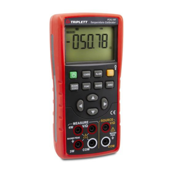
- Page 1 User Manual PCAL100 Temperature Calibrator...
- Page 2 Safety Information User should use the calibrator in accordance with the instructions of the manual, or the protective measures provided by the calibrator may be damaged. The Company is not responsible for any damage caused by failure to follow the safety warning information provided. WARNING “...
- Page 3 • Please follow all safety steps of the instrument. • Do not use a damaged calibrator. Check the housing of the calibrator for cracks or missing plastic parts before use. Pay special attention to the insulation around the connector. • Select the proper function and range according to the measurement requirements. •...
- Page 4 Get to Know the Calibrator...
- Page 5 Figure 1. Overall diagram Figure 2. Input/output terminals Input and output terminals 5.2 Buttons Figure 2 shows the input and output terminals of the calibrator. Table 2 explains their purposes. Figure 3 shows the calibrator buttons. Table 3 explains their functions. 2.
- Page 6 Table 3. Button functions Button name Description Power button Power on/off CONFIG button Configuration button: Set the wire system when inputting resistance; Set the excitation when outputting resistance; Set the compensation in TC function MEASURE/SOURCE Input/output state switching button FUNC button Input/output function switching 5,7 Output setting button...
- Page 7 5.3 Display screen a: Mark for instrument output working mode b: Mark for instrument measurement working mode c: On/off function mark d: Input/output value polarity mark e: Input/output value f: Output bit indicator g: Cold-end compensation temperature value h: Cold-end compensation temperature unit i: Voltage/resistance value corresponding to thermocouple/thermal resistance function j: Voltage/resistance unit corresponding to...
- Page 8 Preparations ◼ Operating precautions Safe use for the calibrator ⚫ When using the calibrator for the first time, be sure to read the safety information listed in Section IV. ⚫ Do not open the instrument housing. To inspect or repair the instrument’s internal components, please contact the seller from whom you purchased the product. ⚫...
- Page 9 Ambient humidity: 20%-80%; use the instrument under non-condensing conditions ⚫ Use the instrument in a flat and horizontal area ◼ Do not use the instrument in the following environment ⚫ Places directly exposed to sunlight or close to heat sources ⚫...
- Page 10 WARNING ⚫ To avoid electric shock, the test lead must be removed from the calibrator before opening the battery door. The battery door must be closed tightly before using the calibrator. Caution ⚫ To prevent the risk of liquid leakage or battery explosion, install the positive and negative poles of the battery correctly. ⚫...
- Page 11 ◼ Power on/off Press the Power button to turn on the calibrator when the power is off; Press the Power button for 2 seconds to turn off the calibrator when it is on. ◼ Automatic shutdown The calibrator automatically shuts down when there is no button operation within the factory default of 5 minutes. The automatic shutdown time can be set in the factory settings.
- Page 12 Utilize the Output Mode Warning Do not apply voltage exceeding the rated voltage between the terminals of the calibrator or between any terminal and the ground indicated on the calibrator or use the calibrator in any case where the terminal to ground voltage should not exceed the peak value of 30V in order to avoid electric shock.
- Page 13 7.3 Analog output resistance Step 1: Press 〔 FUNC〕 button to switch the function to the analog resistance function and the character Ω on the right of the main display area of the LCD display screen will light up. Step 2: Press〔RANGE〕button to switch to the required measurement range (400 Ω / 4K Ω). Measurement range of 400 Ω...
- Page 14 temperature indicates the temperature set by the user. The method of setting the cold end compensation: Press〔CONFIG〕button to enter the cold end compensation setting interface and RJST is displayed in the secondary display area at the lower right corner of the display screen at this moment, indicating the compensation mode setting;...
- Page 15 in the secondary display area at the lower right corner of the display screen at this moment and the characters (I-H stands for 1mA and I-L stands for 0.1mA) corresponding to excitation current are displayed in the main display area. Press〔〕/〔〕 button to change the excitation and press〔ZERO〕button to save the settings;...
- Page 16 8.1 Connect leads to input terminals Connection method of DC voltage, thermocouple, thermal resistance, resistance (2W) measurement (Figure 7) Step1: Connect the black lead to the ‘COM’ end of the input and the red lead to the ‘VΩ’ end of the input. Step2: Connect the other end of the two leads to the measurement end of the device under test and ensure that the terminal polarity is correct.
- Page 17 Connection method of resistance (4W) and thermal resistance measurement (4W) (Figure 9) Step 1: Connect the black lead to the ‘COM’ end of the input, the red lead to the ‘VΩ’ end of the input, the 3W lead to the ‘3W’ end of the input and the 4W lead to the ‘4W’...
- Page 18 8.3 Measurement of resistance Step 1: Ensure the measurement lead is disconnected from the device under test. Step 2: Press〔FUNC〕button to switch to the resistance function and the Ω character on the display screen will light up. Step 3: Press〔RANGE〕button to switch the required measurement range (500Ω / 5KΩ). Step 4: Set the resistance wire system: Press 〔CONFIG〕...
- Page 19 change the setting; Press 〔 ZERO〕 button to save the settings and switch to the manual temperature compensation temperature setting interface. The secondary display area at the lower right corner of the display screen displays RJVA at this time. The main display area displays the temperature to be set.
- Page 20 Factory Settings The calibrator can have changes of the default factory settings. To enter: Press and hold the Backlight button, and then press the Power button to turn on the instrument. After the instrument enters the settings interface, release the Backlight button. 9.1 Automatic shutdown time setting Step 1: After entering the settings interface, you will find “APOF”...
- Page 21 9.3 Flashlight time setting Step 1: Press〔CONFIG〕button to make the display screen show “LTOF”, which indicates the flashlight time setting. Step 2: Use〔〕/〔〕/〔〕/〔〕to set the required parameters. The display unit of flashlight time is minute. Setting range: 0-30 minutes; 0 represents canceling the automatic backlight shutdown, other values represent the corresponding time after which the instrument backlight will shut down.
- Page 22 9.6 Factory default setting Step 1: Press〔CONFIG〕button to make the display screen show “FACT”, which indicates the factory default setting. Step 2: Use〔〕/〔〕to set the required parameters; NO indicates that all settings are not restored to factory parameters, while YES indicates that all settings are restored to factory parameters.
- Page 23 10 Replace the Battery WARNING To avoid electric shock, the test lead must be removed from the calibrator before opening the battery door. The battery door must be closed tightly before using the calibrator. Caution ◼ To prevent the risk of liquid leakage or battery explosion, install the positive and negative poles of the battery correctly. ◼...
- Page 24 11 Maintenance 11.1 Clean the calibrator WARNING Designated replacement parts should be used to avoid personal injury or damage to the calibrator. Do not allow water to enter the housing. Caution Do not use solvent or abrasive cleaner to avoid damage to the plastic lens and housing. Clean the calibrator with a soft cloth dampened with a little water or mild soapy water.
- Page 25 12 Index Input measurement function [Used within one year after calibration, 23℃±5℃, 20-70% RH, accuracy = ± (% set value + reading)] Measurement Range Measurement range Resolution Accuracy Remarks function 100mV -110.000mV~110.000mV 0.01mV 0.05%+0.03mV DC voltage Input resistance: -1.1000V~1.1000V 0.0001V 0.05%+0.3mV approximately 1MΩ...
- Page 26 less 0.05%+3℃( Use ITS-90 temperature than or equals scale 0C~1767C The accuracy does not include the error of 1C 100C) cold-end compensation more 0.05%+2℃( 0C~1767C The accuracy does not than include sensor inaccuracy 100C) accuracy does include the influence of -100.0~1372.0C thermoelectric potential Thermocouple...
- Page 27 copper nickel (constantan) -200.0~1300.0C J: Iron - copper nickel (constantan) T: Copper - copper nickel 600C~1820C 1C (constantan) N: Nickel chromium silicon - nickel silicon 0C~2500C 1C B: Platinum Rhodium 30 - Platinum 0.05%+3℃ A: Tungsten rhenium 5- Tungsten rhenium 20 0C~2310C 1C C: Tungsten rhenium 5-...
- Page 28 (3W) 2W/3W/4W measurement Pt200 500Ω approximately 1mA -200.0C~630.0C excitation 5KΩ approximately 0.1mA excitation Pt500 Open circuit voltage: -200.0C~630.0C approximately 2.5V The accuracy does not include the error caused Pt1000 by the mismatch of the 2 -200.0C~630.0C W/3 W measurement lead resistance The accuracy does not include sensor inaccuracy...
- Page 29 Other characteristics: ⚫ Uncertainty includes standard uncertainty, hysteresis, nonlinearity, repeatability, and typical long-term stability over the period mentioned (K = 2). ⚫ Display refresh rate: 2-3 times / second. ⚫ Maximum applied voltage at input terminal: 60 Vpk. ⚫ Input common-mode rejection: 50Hz /60 Hz > 80 db; Input serial-mode rejection: 50Hz /60 Hz > 40 db ⚫...
- Page 30 Analog output function [Used within one year after calibration, 23℃±5℃, 20-70% RH, accuracy = ± (% set value + reading)] Output Range Output range Resolution Accuracy Remarks function 100mV -10.000mV~110.00mV 0.01mV 0.05%+0.03mV Maximum output current: 0.5mA DC voltage -0.1000V~1.1000V 0.0001V 0.05%+0.3mV Maximum output current 2mA The excitation current is...
- Page 31 compensation 100C) The accuracy does not include more 0.05%+2( 0C~1767C sensor inaccuracy than The accuracy does not include 100C) influence thermoelectric potential -200.0C~1372.0C The materials corresponding to the calibrations on the left are as follows: R: Platinum Rhodium 13- -200.0C~1000.0C less 0.05%+20(...
- Page 32 N: Nickel chromium silicon - nickel silicon 600C~1820C 1C B: Platinum Rhodium 30 - Platinum A: Tungsten rhenium 5- 0C~2500C 1C Tungsten rhenium 20 C: Tungsten rhenium 5- 0.05%+3 Tungsten rhenium 26 0C~2310C 1C Tungsten rhenium Tungsten rhenium 25 0C~2310C 1C Pt100 Use Pt (385) temperature...
- Page 33 error of 0.3Ω is added Pt1000 -200.0C~630.0C The accuracy does not include lead resistance The accuracy does not include Cu50 -50.0C~150.0C influence thermoelectric potential Other characteristics: ⚫ Uncertainty includes standard uncertainty, hysteresis, nonlinearity, repeatability, and typical long-term stability over the period mentioned (K = 2).
Need help?
Do you have a question about the PCAL100 and is the answer not in the manual?
Questions and answers