Advertisement
Quick Links
Advertisement

Related Manuals for Triplett PR600


Summary of Contents for Triplett PR600
- Page 1 User Manual PR600 Non-Contact Phase Sequence Detector...
-
Page 2: Table Of Contents
INDEX PAGE 1. INTRODUCTION......2. SAFETY NOTES....... 3. FEATURES........4. SPECIFICATIONS......5. INSTRUMENT LAYOUT....6. MEASUREMENT......7. LIVE WIRE CHECK......8. MAINTENANCE........ 11-12 Due to our policy of constant improvement and development, we reserve the right to change specifications without notice. -
Page 3: Introduction
1. INTRODUCTION This Non-Contact PHASE DETECTOR has been designed and tested According to CE Safety Requirements for Electronic Measuring Apparatus, IEC/EN 61010-1 and other safety standards. Follow all warnings to ensure safe operation. WARNING READ "SAFETY NOTES" (NEXT PAGE) BEFORE USING THE NON-CONTACT DETECTOR. -
Page 4: Safety Notes
2. SAFETY NOTES 1. Read the following safety information carefully before attempting to operate or service the detector. 2. Use the detector only as specified in this manual. Otherwise, the protection provided by the detector may be impaired. 3. This instrument cannot find the missing line of earth line (S line). - Page 5 (6) Ambient temperature 0~40 ℃ . 11. Observe the International Electrical Symbols listed below: Detector is protected throughout by double insulation or reinforced insulation. Warning ! Risk of electric shock. Caution ! Refer to this manual before using the detector. AC..Alternating current.
-
Page 6: Features
3. FEATURES ● Protection class: IP40 ● 895 PR is a phase detector with LED display lights and beeping buzzer to inform the detection of AC 3-phase sequence. ● Two functions in one unit: open phase and phase sequence. ● Auto-off. (5 min Approx.) ●... -
Page 7: Specifications
4. SPECIFICATIONS Measurement Principle Static induction Input Voltage 75~1000Vac Frequency Range 45-65Hz 5 min. after power on without Auto-Off detection Power LED flashes at Low Battery Warning 7.0±0.2V or less Current consumption 20mA Operating Temperature -10 ºC~50 ºC Max. 80% R.H. &... -
Page 8: Instrument Layout
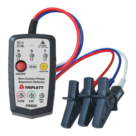
5. INSTRUMENT LAYOUT Buzzer Open phase indicator Power Button IP40 BRIGHTER Brightness Button ON/OFF Non-Contact Phase Sequence Detector Battery LED BAT. PR600 Phase sequence LEDs... - Page 9 Magnet Warning label Battery cover Magnet Magnets for mounting is equipped on the back of this product allow for hands-free use.
-
Page 10: Measurement
6. MEASUREMENT Before proceeding with measurement, read the safety notes. 1. Press the power button to turn on the instrument. All of the LEDS will flash during the 2 seconds. Only the power LED stays on at the self demonstration later. - Page 11 Lines connecting the apexes of "▼" marks should pass through the center of the conductor. 3. Measure a covered conductor AC75V or more first to confirm each live LED lights up. 4. Presence of live wires and phase sequence are informed by LED indication and buzzer beeping as soon as complete detection.
-
Page 12: Live Wire Check
7. LIVE WIRE CHECK State Indication Phase with R, S, T ON is Live live state LED does not light up for Missing line of Earth line missing line of earth line Earth line Phase with flashing LED is (Delta connection) an earth phase When the Green CW LED ON, the circuit is forward... -
Page 13: Maintenance
8. MAINTENANCE ● Battery replacement: When low battery LED flashes, replace with new battery. Follow these steps for battery replacement: (1) Remove all the clips from the conductors and power off the instrument. (2) Loosen the screw that secures the battery compartment cover and open cover. - Page 14 ● Cleaning and storage Periodically wipe the case deterged with a damp cloth; do not use abrasives or solvents. After the instrument has been turned off, the standby current is below 40uA. If the meter is not to be used for periods of longer than 60 days, remove the batteries and store them separately.
- Page 16 Warranty Triplett / Jewell Instruments extends the following warranty to the original purchaser of these goods for use. Triplett warrants to the original purchaser for use that the products sold by it will be free from defects in workmanship and material for a period of (1) one year from the date of purchase.
Need help?
Do you have a question about the PR600 and is the answer not in the manual?
Questions and answers