
Subscribe to Our Youtube Channel
Related Manuals for Triplett hotwire fox


Summary of Contents for Triplett hotwire fox
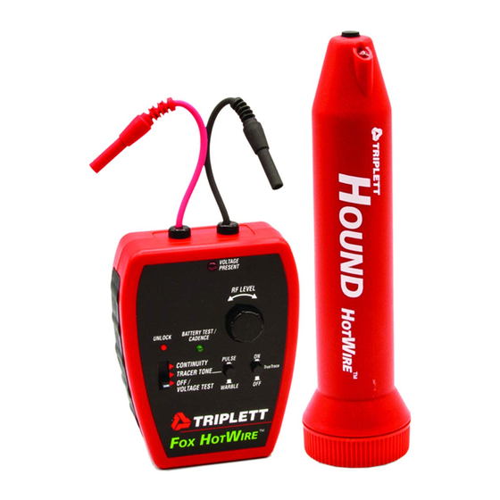
- Page 1 TRIPLETT HotWire Fox & Hound Live Wire Circuit Tracing Kit Instruction Manual 84-877 7-10...
-
Page 2: Table Of Contents
Warnings and Cautions ........... Specifications for HotWire Fox ........ Specifications for HotWire Hound ......General Characteristics ........... Control Location for HotWire Hound ....... Control Location for HotWire Fox ......Getting Started ............Detailed Operation ..........Internal Settings ............. Included Items ............ -
Page 3: Features
* White LED Headlights * Auto-Muting Earphone Jack * Easy Battery Replacement HotWire Fox Features * Generates Warble or Pulsed Tracing Tones with User Selectable Pitch * LED and Beeper ‘Voltage Present’ Indicators * Audible Continuity Test with 120/220 VAC Line Cross Protection... -
Page 4: Introduction
Fox, in addition to generating RF signals, also generates Audio Frequency (AF) signals which can be sensed with the Triplett Hound, Hound 2, Hound 3, or Hound Jr. In some cases, tracing a wire using the AF signal is advantageous. -
Page 5: Warnings And Cautions
AC power to the circuit. * If connecting to a live circuit, always wear eye protection, insulating gloves, and non-flammable clothing. Connect one lead of the HotWire Fox to the Neutral wire first, and then connect the other lead to the HotWire. -
Page 6: Specifications For Hotwire Fox
4: Specifications for HotWire Fox * Operating Frequency (RF): 400KHz to 500KHz * Operating Frequency (AF): 800Hz to 2400Hz * Output Voltage (RF): adjustable from approx. 5Vpp to 30Vpp (open circuit) * Output Voltage (AF): fixed, approx 10Vpp (open circuit) * Tracer Tone: Warble or Pulsed, High or Low Pitch * TrueTrace: Tracer Tone changes Cadence (from approx 2Hz to approx 7Hz) when leads are ‘shorted’... -
Page 7: Specifications For Hotwire Hound
5: Specifications for HotWire Hound * Operating Frequency (RF): 400KHz to 500KHz * Signal Indicators: Speaker outputs Tracer Signal and LED indicates signal strength * Earphone Jack: Accepts 1/8” mono or stereo earphone plug, 8 Ohms to 50 Ohms. Automatically mutes speaker. -
Page 8: General Characteristics
2, Hound 3, and Hound Jr) use a different technology (AF) than the HotWire (RF). AF works better for identifying specific wires in a group of wires. The HotWire Fox does have an AF feature built into it, but the HotWire Hound does not work with AF. Most of the HotWire’s circuits are used to support its RF fea- tures. - Page 9 LAN cables. HotWire Technology The Triplett HotWire is a Radio Frequency (RF) Wire Tracer. RF tracers like the Triplett HotWire share certain characteristics that can be perplexing to an inexperienced user. While the RF signal provides the HotWire with the ability to trace AC power wires that are ‘live’, a disadvantage to using the RF signal is its...
- Page 10 The ground wire from the HotWire Fox is connected to a metal rod driven into the earth (not a ‘ground’ in a wall outlet, or other electrical ground).
- Page 11 Simply connecting a wire from the HotWire Fox to the wire we want to trace doesn’t necessarily produce a ‘circuit’ that the HotWire Hound will locate and trace.
- Page 12 7: HotWire Hound Control Locations A: ANTENNA B: LED HEADLITES C: SIGNAL STRENGTH INDICATOR D: POWER BUTTON E: VOLUME / SENSITIVITY CONTROL F: EARPHONE JACK G: BATTERY CONNECTOR H: BATTERY STRAP I: BATTERY COVER J: 9V BATTERY K: SPEAKER A) Antenna This area contains the RF sensing antenna.
- Page 13 LED to light. The user will note that the HotWire Hound will “pick up” signals from electrical de- vices other than the HotWire Fox. Equipment with motors and electronic displays often produce RF noises that can be heard with the HotWire Hound. The Signal Strength LED can’t differentiate between these sig- nals……...
- Page 14 G) Battery Connector Observing proper polarity, attach to 9V alkaline battery H) Battery Strap Slip over battery before installing in Hound. Position tab so it can be grabbed with fingers. This allows bat- tery to be removed easily when it needs to be replaced. I) Battery Cover Removed and replaced easily using snap tab.
- Page 15 8: HotWire Fox Control Locations 1) FUNCTION SWITCH 2) UNLOCK BUTTON 3) BATTERY TEST / CADENCE LED (GREEN) 4) VOLTAGE PRESENT LED (RED) 5) PULSE / WARBLE BUTTON 6) TRUETRACE ON/OFF BUTTON 7) RF LEVEL CONTROL 8) TEST LEADS (PIGTAILS)
- Page 16 BEEPER. a) In the OFF / VOLTAGE TEST setting, the HotWire Fox is turned off (not using any battery power) and is configured to test for AC or DC voltage on its Test Leads. If AC or DC voltage is detected (see Specifica- tions for details), the beeper sounds and the VOLTAGE LED flashes.
- Page 17 8) Test Leads The short ‘pigtail’ Test Leads connected to the HotWire Fox are designed to connect to the 2’ or 5’ leads. Either of these leads can be used to connect to any of the supplied probes. 9) Magnets Magnets on the rear of the HotWire Fox allow it to be temporarily attached to steel surfaces, like electrical panels, appliances, junction boxes, etc.
-
Page 18: Getting Started
Earphone Jack (F) first, and snapping the opposite end of the Cover to the case. To install or replace the 9 volt battery in the HotWire Fox, remove the Battery Cover (10) by inserting a fingernail or small screwdriver into the slot below the bottom magnet. The Cover will snap loose. Remove the Cover completely by sliding it straight down. -
Page 19: Detailed Operation
Using the Test Leads Any test performed with the HotWire Fox requires the use of test leads. The HotWire kit includes a set of Modular Test Leads that can be configured for various test scenarios. Included is a set of short (2’) and long (5’) leads, Flat and Pointed Probes, and modular and screw-on Alligator Clips. - Page 20 OFF / VOLTAGE TEST Function The HotWire Fox has a built-in Voltage Detector. It is intended to warn the user that voltage is present, and the proper precautions should be taken. To use the Voltage Detector, set the Function switch on the HotWire Fox to the OFF / VOLTAGE TEST position.
- Page 21 TRACER TONE Test Function Several different methods can be and should be employed to trace wires. Set the Function switch to the TRACER TONE position. The BATTERY TEST / CADENCE LED must flash. If it does not flash, replace the battery. Select the PULSE or WARBLE mode as desired.
- Page 22 HotWire Fox to the target circuit and see if it nulls by itself. For example, connect the HotWire Fox to a wall outlet (the polarity is not important), trace the wire through the wall by finding the null, and locate the target circuit breaker by finding the null over the breaker.
- Page 23 HotWire Fox connected to wall outlet Tracing wire in wall Identifying breaker by locating the “null”. Page 22...
- Page 24 Helpful Hints It is usually best to start with the RF Level control all the way up on the HotWire Fox, adjusting the Sen- sitivity on the HotWire Hound so the tracer signal produces a comfortable loudness. If it is found that the Sensitivity of the HotWire Hound is turned almost all the way down, it may be hard to detect the peak or null of the target wire.
- Page 25 When the actual earth is available, lay the HotWire Fox on the earth and connect the 5’ black lead to the HotWire Fox’s black pigtail, and string the black lead out on the surface of the earth. In the following photo, the black lead is coiled up.
- Page 26 HotWire Fox on ‘Earth’ Connect the red pigtail to either the 2’ or 5’ red test lead (use the shortest one you can), and connect the other end of the test lead to the wire to be traced. In the following photo, the target wire is connected to a wall outlet.
- Page 27 If the wall outlet is ‘live’, the black test lead will be live also. Use ap- propriate caution. Failure to do so could result in user injury. When using ‘single wire’ connection, the HotWire Fox will not indicate if the target wire is ‘live’. If you do not know if the target wire is ‘live’, use appropriate caution.
- Page 28 Peak signal pick up usually happens when short wires are being traced, and the wires have no predomi- nant RF path to earth ground. On a long wire run, the signal near the HotWire Fox may display null characteristics, and gradually change to peak characteristics towards the far end of the wire.
- Page 29 When the HotWire Fox is initially set to the TRACER TONE mode, it may come on with either fast or slow cadence.
- Page 30 If possible, use the AF mode to identify specific wires in a group of wires. The Triplett Hound 3 is a good inductive amplifier for AF tracing. Keep in mind that AF can only be used on unenergized wires.
-
Page 31: Internal Settings
Noise Pickup: The HotWire Hound is tuned to the frequency of the HotWire Fox. RF noise is also found in this same frequency range. Noise comes from Light Dimmers, Motor speed controls, Power Paks (Wall Warts), Computers, etc. The HotWire Hound may also pick up radio or TV stations. Because electrical wiring often acts like an antenna, the HotWire Hound may pick up radio or TV stations as the Hound is brought close to these electrical wires. -
Page 32: Included Items
DOING SO MAY DAMAGE THE PRODUCT OR INJURE THE USER. To test the fuses, set the HotWire Fox to it’s CONTINUITY function and short the test leads. The beeper should sound. If the beeper does not sound, the fuses maybe blown. - Page 33 Triplett Product Return Instructions In the unlikely event that you must return your Triplett equipment for repair, the following steps must be taken. 1) Call 1-800-TRIPLETT to obtain a Return Material Authorization (RMA) number from Customer Service. 2) Enclose a copy of the original sales receipt showing date of purchase.
-
Page 34: Warranty
No representative of Triplett / Jewell Instru- ments or any other person is authorized to extend the liability of Triplett in connection with the sale of its products beyond the terms hereof. - Page 35 TRIPLETT Test Equipment & Tools 850 Perimeter Road, Manchester, NH 03103 PHONE: 800-TRIPLETT FAX: 603-622-2960 www.triplett.com...
Need help?
Do you have a question about the hotwire fox and is the answer not in the manual?
Questions and answers