
Related Manuals for Triplett PQC300


Summary of Contents for Triplett PQC300
- Page 1 User Manual PQC300 AC/DC True RMS Power Analysis Clamp MeterOperating Instruction for AC/DC TRMS H&W ANALYSIS CLAMP METER safety...
- Page 2 AC/DC TRMS H&W ANALYSIS CLAMP METER Features • AC TRMS voltage • DC voltage and AC+CD TRMS voltage • Phase sequence • Active, reactive, apparent power and power factor on single-phase • Active, reactive, apparent energy on single-phase systems • AC voltage harmonics (1-25) and THD% up to 75Hz (1-8 above 75Hz) •...
- Page 3 2-4.CAUTIONS • Read and understand this user manual before operating the meter. • Improper use of this meter can cause damage, shock, injury or death. • Always remove the test leads before replacing the battery . • If the test leads need to be replaced, you must use a new one which should meet EN 61010-031 standard.
-
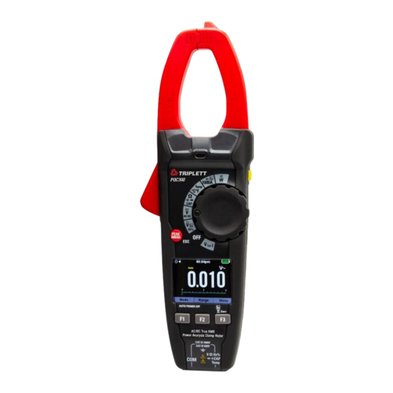
Page 4: 3-1.Meter Description
AC/DC TRMS H&W ANALYSIS CLAMP METER 3.Description 3-1.Meter Description NCV Test 9-F1 Button Current Clamp 10-F2 Button Non-Contact AC Voltage Indicator Light 11-F3 Button 4-Clamp Trigger 12-Flashlight 5-Data Hold/Flashlight Button 13-Battery Cover 6-Rotary Function Swith 14-COM Input Jack 15-Positive Input Jack 7-Peak/Inrush/ESC Button 8-LCD Display 1000A... - Page 5 3-2.Display Icons Description Measuring Unit 1-Auto Power Off Measuring Result 2-Key Beeper Analogue Bar Graph 3-Automatic/Manual Mode Indications Associated with Function Keys 4-System’s Time Battery Capacity 3-3.Description of Function Keys 3-3-1.Peak/Inrush/ESC Button • PEAK Function Note: Only ACV functions can do the peak value measurement. 1.PEAK Key is the peak value measurement key that acts with trigger.
- Page 6 AC/DC TRMS H&W ANALYSIS CLAMP METER 3-3-2.Data Hold/Flashlight Button • To freeze the LCD reading, press the Data Hold/Flashlight Button. • While data hold is active, the HOLD icon appears on the LCD, press the Data Hold/Flashlight Button again to return to normal operation. •...
- Page 7 3-4.Description of Internal Functions 3-4-1.Save Function Press the Data Hold/Flashlight Button to freeze the result, the message “Hold” appears on the display. Press the F1 (Save) Key to save the data in the instrument’s memory. 3-4-2.Relative Values To activate the relative mode, press and hold the F3 Key for more than 2 second to enter the selection interface.
- Page 8 AC/DC TRMS H&W ANALYSIS CLAMP METER 3-5.Individual Harmonic Measurement Function 3-5-1.Voltage Measurement Mode Press and hold the F3 Button for more than 2 second to enter the selection interface. Press the F2 (Har) Button to enter Harmonic Measurement, press the F2 Button again to go back.
- Page 9 Press the F2 Button to enter the DC Power test interface, which measures DC Power, DC Current, DC Voltage. Press and hold the F3 Button to enter the Harmonic Voltage Current Analysis interface of power, including Voltage Harmonic Analysis Maps, Harmonic Current Analysis Maps and Electrical Energy Testing.
- Page 10 AC/DC TRMS H&W ANALYSIS CLAMP METER 3-7.SETUP Press the F3 Button to enter the Installation Settings interface, you can set the Key Sound, Automatic Shutdown Time, Time Format Switch. • Key Sound: Allows activating/deactivating the tone of the function keys. •...
- Page 11 3-9-3.Recall Harmonics • Press the F1 Button to enter the data view, F1 to delete the data, F2 to turn the page up, F3 to enter the TREND Menu. • Press the ESC Button to exit the view. 3-9-4.Delete Harmonics •...
- Page 12 AC/DC TRMS H&W ANALYSIS CLAMP METER Delete Recordings • Press the F1 Button to enter the Data View, F1 delete the data, F3 returns to the Previous Menu. • Press the ESC Button to exit the view. 3-11.Meter Info • Press the F3 Button to enter the Instrument Information Interface, F1 returns to the Previous Menu.
-
Page 13: Operation
4.Operation Notes: Read and understand all WARNING and CAUTION statements in this operation manual prior to using this meter. 4-1.Individual Harmonic Voltage Measurement Set the function switch to the VAC Hz% Position. Insert the black test lead banana into the COM Input Jack; Insert the red test lead banana into the Positive Input Jack. - Page 14 AC/DC TRMS H&W ANALYSIS CLAMP METER 4-2.Individual Harmonic Current Measurement WARNING: Ensure that the test leads are disconnected from the meter before making current clamp measurements. Set the function switch to the 1000AAC/DC Position. Press and hold the F3 Button for more than 2 second to enter the selection interface and press the F2 (Har) Button to enter Harmonic Measurement.
- Page 15 4-3.Measuring AC Power (Active, Apparent, Reactive)/Power Factor (PF)/ Displace Power Factor Set the rotary switch to the W Position. Insert the black test lead banana into the COM Input Jack; Insert the red test lead banana into the Positive Input Jack. Press the trigger to open the transformer jaws and clamp one conductor only, make sure that the jaw is firmly closed around the conductor.
- Page 16 AC/DC TRMS H&W ANALYSIS CLAMP METER 4-4.Measuring DC Power Set the rotary switch to the W Position. Insert the black test lead banana into the COM Input Jack; Insert the red test lead banana into the Positive Input Jack. Press the trigger to open the transformer jaws and clamp one conductor only, make sure that the jaw is firmly closed around the conductor.
- Page 17 4-5.Energy (Active, Apparent, Reactive) Set the rotary switch to the W Position. Insert the black test lead banana into the COM Input Jack; Insert the red test lead banana into the Positive Input Jack. Press the trigger to open the transformer jaws and clamp one conductor only, make sure that the jaw is firmly closed around the conductor.
- Page 18 AC/DC TRMS H&W ANALYSIS CLAMP METER 4-6.AC/DC Current Measurement WARNING: Ensure that the test leads are disconnected from the meter before making current clamp measurements. Set the Function Switch to the 1000AAC/DC range. In DC Current mode Press the F1 (REL) Button to zero the meter display. 3.Use the F1 (MODE) Button to select AC or DC Current.
- Page 19 4-7.AC Voltage Measurement Set the rotary switch to the VAC Position. Insert the black test lead banana into the COM Input Jack; Insert the red test lead banana into the Positive Input Jack. Connect the test leads in parallel to the circuit under test. 4.Read the voltage measurement on the LCD display.
- Page 20 AC/DC TRMS H&W ANALYSIS CLAMP METER 4-8.DC (AC+DC) Voltage Measurement Set the rotary switch to the VDC AC+DC Position. Insert the black test lead banana into the COM Input Jack; Insert the red test lead banana into the Positive Input Jack. Connect the test leads in parallel to the circuit under test.
- Page 21 4-9.Low Z Voltage Measurement WARNING: Observe all safety precautions when working on live live voltages. Do not connect to circuits that exceed 600V AC/DC when the meter is set to Low Z. • Low Z is used to check for “ghost” voltage. •...
- Page 22 AC/DC TRMS H&W ANALYSIS CLAMP METER 4-10.Resistance Measurement Set the rotary switch to the Ω CAP Position. Insert the black test lead banana into the COM Input Jack; Insert the red test lead banana into the Positive Input Jack. Touch the test probe tips across the circuit or component under test. 4.Read the resistance on the LCD display.
- Page 23 4-11.Continuity Check Set the rotary switch to the Ω CAP Position. Insert the black test lead banana into the COM Input Jack; Insert the red test lead banana into the Positive Input Jack. Use the MODE Button to select continuity “ ”, the display icons will change when the MODE Button is pressed.
- Page 24 AC/DC TRMS H&W ANALYSIS CLAMP METER 4-12.Diode Test Set the rotary switch to the Ω CAP Position. Insert the black test lead banana into the COM Input Jack; Insert the red test lead banana into the Positive Input Jack. Use the MODE Button to select the diode function if necessary (Diode symbol will appear on the LCD when in Diode test mode).
- Page 25 4-13.Capacitance Measurement WARNING: To avoid electric shock, discharge the capacitor under test before measuring. Set the rotary switch to the Ω CAP Position. Insert the black test lead banana into the COM Input Jack; Insert the red test lead banana into the Positive Input Jack. Touch the test probe tips across the part under test, if “OL”...
- Page 26 AC/DC TRMS H&W ANALYSIS CLAMP METER 4-14.Frequency Measurement WARNING: To avoid electric shock, discharge the capacitor under test before measuring. Set the rotary switch to the VAC Hz% Position. Insert the black test lead banana into the COM Input Jack; Insert the red test lead banana into the Positive Input Jack.
- Page 27 4-15.Temperature Measurement WARNING: To avoid electric shock, be sure the thermocouple probe has been removed before changing to another measurement function. 1.Set the function switch to the TEMP Position. 2.Use the MODE Button to select °C or °F. Insert the Temperature Probe into the negative COM and the Positive Input Jack, observing polarity.
- Page 28 AC/DC TRMS H&W ANALYSIS CLAMP METER 4-16.Non-Contact AC Voltage Measurement WARNING: Risk of Electrocution. Before use, always test the Voltage Detector on a known live circuit to verify proper operation. Touch the probe tip to the hot conductor or insert into the hot side of the electrical outlet.
-
Page 29: Automatic Power Off
Automatic Power OFF • In order to conserve battery life, the meter will automatically turn off after approximately 15 minutes. • To turn the meter on again, turn the function switch to the OFF Position and then to the desired function position. Maintenance WARNING: To avoid electrical shock, disconnect the meter from any circuit, remove the test leads from the input terminals, and turn OFF the meter before... -
Page 30: Specifications
AC/DC TRMS H&W ANALYSIS CLAMP METER 7.Specifications 7-1.Technical Specifications Accuracy calculated as [%reading + (num. digits*resolution)] at 18 to 28°C; <75%HR. Function Range Resolution Accuracy 600.0mV 0.1mV ±(0.5% + 8 digits) DC Voltage 6.000V 0.001V 60.00V 0.01V ±(1.5% + 5 digits) 600.0V 0.1V 1000V... - Page 31 Function Range Resolution Accuracy 600.0 Ω 0.1 Ω ±(1.0% + 10 digits) Resistance and 6.000k Ω 0.001k Ω Continuity Test 60.00k Ω 0.01k Ω ±(1.5% + 5 digits) 600.0k Ω 0.1k Ω 6.000M Ω 0.001M Ω ±(2.5% + 5 digits) 60.00M Ω...
-
Page 32: Function Range
AC/DC TRMS H&W ANALYSIS CLAMP METER Function Harmonic Base Wave Resolution Accuracy Orde Frequency 1-25 20-75Hz 0.1% THD ±(5.0% + 8 digits) Voltage Harmonics 75-400Hz 0.1% THD ±(6.0% + 8 digits) Protection against overcharge: 1000VDC/ACrms Uncertainty defined for: Voltage >10V; Below 2% of voltage range, add 20 counts. Current 1-25 20-75Hz... - Page 33 7-2.General Specifications Clamp Jaw Opening 1.26” (33mm) approx. Display 6000 counts RGB LCD Low Battery Indication “ ” is displayed Over-Range Indication Over-range indication “OL” display Measurement Rate 3 readings per second, nominal PEAK Captures peaks >1ms INRUSH 100ms Temperature Sensor Type K thermocouple Input Impedance 10MΩ(VDC and VAC)
- Page 34 Warranty Triplett / Jewell Instruments extends the following warranty to the original purchaser of these goods for use. Triplett warrants to the original purchaser for use that the products sold by it will be free from defects in workmanship and material for a period of (1) one year from the date of purchase. This...
Need help?
Do you have a question about the PQC300 and is the answer not in the manual?
Questions and answers