Advertisement
Quick Links
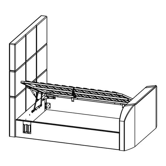
OPEN FROM RIGHT
IMPORTANT: BEFORE STARTING TO ASSEMBLE THE BED - PLEASE READ THESE INSTRUCTIONS CAREFULLY.
Parts Identification
3
2
1
5
Parts Checklist
Ref.
Description
1
Headboard - Bottom
2
Headboard - Middle
3
Headboard - Top
4
Footboard
5
Side Rails
6
Metal Slat Frame
7
Base Boards
8
Angle Brackets
9
Mattress Stoppers
210414
OPEN FROM LEFT
8
6
5
7
7
Qty
1
1
1
1
2
1
2
4
2
Page 1 of 19
SOMERTON OTTOMAN TV BED
PLEASE READ this sheet prior to assembly to familiarise
yourself with the various stages of construction.
Carefully open the pack supplied and check the contents
against the parts and fittings check list.
Do not destroy any of the packaging until you are certain
that you have all the necessary parts for the assembly.
Please ensure that the packaging is disposed of in
a safe environmentally friendly way.
CAUTION: There are small components used in the
construction of this unit. These loose items should be kept
away from young children during assembly, to avoid the
danger of choking.
9
FABRIC HAND STRAP
Ref.
Description
10
Mains Power Lead - 3 mt
11
Aerial Lead - 4 mt
12
HDMI Leads - 2.8 mt
13
HDMI Adaptor 90º
14
C able Clips
15
Cable Ties
16
TV Lift Remote Control
17
Holster for Remote Control
10
11
13
14
16
4
Inside
accessory
box
12
15
17
Qty
1
1
2
1
3
3
1
1
Advertisement

Subscribe to Our Youtube Channel
Related Manuals for Time4Sleep SOMERTON


Summary of Contents for Time4Sleep SOMERTON
- Page 1 SOMERTON OTTOMAN TV BED OPEN FROM LEFT PLEASE READ this sheet prior to assembly to familiarise yourself with the various stages of construction. Carefully open the pack supplied and check the contents against the parts and fittings check list. OPEN FROM RIGHT Do not destroy any of the packaging until you are certain that you have all the necessary parts for the assembly.
- Page 2 Fittings Checklist HARDWARE NEEDED FOR FITTING GAS-LIFT MECHANISMS (PACK A) Ref. Description Ref. Description Bolts (M8x30mm) for fitting gas-lift mechanisms (E) E(a) to headboard & footboard (1&4) Spring washers for M8 bolts Gas-Lift mechanisms Flat washers for M8 bolts E(b) Allen key for M8 bolts HARDWARE NEEDED FOR BED ASSEMBLY (PACK B) Ref.
- Page 3 Care & Maintenance Approximate time to In the unlikely event of missing or damaged parts, assemble this product please contact your retailer. Please have this guide at hand quoting the part code reference numbers shown 2 1/2 Hrs when requesting spare or replacement parts. Lay headboard parts 1 and part 2 face down on a dry, Stage clean floor making sure they are laying flat.
- Page 4 Choose which side of bed to open & prepare head & foot ends - use hardware pack 'A&B' LIFTING UP THE SLAT FRAME FROM LEFT SIDE OF BED IS SHOWN HERE Stage E(a) E(b) LEFT SIDE CHECK THIS DIAGRAM AND IF ACCESS IS NEEDED FROM LEFT SIDE OF BED, FIT BOTH LIFT MECHANISMS TO RIGHT SIDE OF THE HEADBOARD &...
- Page 5 Choose which side of bed to open & prepare head & foot ends - use hardware pack 'A&B' LIFTING UP THE SLAT FRAME FROM RIGHT SIDE OF BED IS SHOWN HERE Stage RIGHT SIDE E (a) E (b) CHECK THIS DIAGRAM AND IF ACCESS IS NEEDED FROM RIGHT SIDE OF BED, FIT BOTH LIFT MECHANISMS TO LEFT SIDE OF THE HEADBOARD &...
- Page 6 Bed A ssembly Stage & Electrical & Cable Connections Stage Connect Main Power Lead (10) to your wall socket - for safety, this must be an earthed supply. Page 6 of 19...
- Page 7 Stage Press the “UP” button to raise the TV lift. Note: For illustration purposes Stage only, TV connections may vary. TV Power Lead TIP: supplied with your TV BEFORE FITTING THE TV, PUSH CABLES THROUGH EACH DUCT FROM THE TOP. CHOOSE THE BEST SIDE TO USE DEPENDING ON WHERE THE CONNECTION PORTS...
- Page 8 TV Installation - Normal Vesa Fixing IF SCREWS ARE SUPPLIED WITH TV, PLEASE USE THOSE IN PREFERENCE Stage Counter-Sunk Screws a x2 Screw-Washer sets Counter-Sunk (M6x12mm) (M8x25mm) Screws (M4x12mm) Use 4mm Allen Key (Q) Use 4mm Allen Key (Q) b x2 Allen Key (2.5mm) 200mm Loosen...
- Page 9 TV Installation - 100x100 Vesa Fixing Stage REMOVE CROSS-BRACKET 100mm AND FIX IT DIRECTLY TO BACK OF TV IF SCREWS ARE SUPPLIED WITH TV, PLEASE USE THOSE IN PREFERENCE Stage Counter-Sunk Screws a x2 Screw-Washer sets Counter-Sunk (M6x12mm) (M8x25mm) Screws (M4x12mm) Use 4mm Allen Key (Q) Use 4mm Allen Key (Q) b x2...
- Page 10 TV Installation Kit - 100x100 Vesa Fixing Stage Loosen Tighten Page 10 of 19...
- Page 11 Note: For illustration purposes Stage only, TV connections may vary. TV Power Lead supplied with your TV 90º ADAPTOR PLUG IN - KEEP ALL CABLES TIGHT - USE CLIPS & TIES PROVIDED. Keep wires tight - peel off cover from cable clips &...
- Page 12 Stage Press the “DOWN” TV Power Lead button to lower the supplied with your TV TV lift. Stage IMPORTANT: Be careful to keep the two HDMI Leads (12) on top of the Base Boards. Main power lead (10) and aerial lead (11) should be kept under the base boards &...
- Page 13 ' B ' Stage & Stage & Make certain the bed is squared up as shown in the diagram then tighten all bed assembly bolts 100%. Page 13 of 19...
- Page 14 ' C ' Stage To top of slat frame, fit the two connection plates (M). Using four sets of bolts (N), spring washers (B) & flat washers (C), screwing into the threaded inserts on top of the frame. Lift Support bars & lay on the slat frame Stage Slat Frame Support Bar &...
- Page 15 Stage Bolt into centre of long holes Stage Carefully lay frame down. Make sure there is an even gap each side of about 8mm, as in the sketch. Hold frame securely then tighten all six bolt sets 100% using spanner (L) & Allen key (D) Page 15 of 19...
- Page 16 Stage During this next step the assistant should hold up the slat frame. On both mechanisms (E) slide gas-lift piston stems (X) onto the axles (Y) then fit the flanged lock-nuts (K). SMALL GAP Tighten nuts with spanner (L) - but DO NOT over-tighten.
- Page 17 Stage Fit RC holster to left or right side. Note: Be very careful what you store under the bed -the top of an Stage item, like a suitcase or a box, must not touch the slats or they may be damaged. Maximum storage height is 260mm. 1 Before lifting the slat frame, place your mattress on top of the slats as without a mattress in place the speed of movement is quick and may cause injury so be careful.
- Page 18 Occasionally you may find the radio wave connection between remote control and TV Lift is lost, probably due to atmospheric conditions. In that case please follow these simple instructions: ①. Disconnect all mains electric power to the bed, for at least 60 seconds. ②.
- Page 19 TV BED SAFETY INFORMATION GENERAL INFORMATION It is very important not to place any vessel containing liquids, e.g. drinks or vase of flowers, on top of the TV footboard which may accidentally spill and enter the TV compartment as this could cause damage to the TV and/or the TV lifting equipment.
Need help?
Do you have a question about the SOMERTON and is the answer not in the manual?
Questions and answers