Advertisement
Quick Links
www.ti.com
EVM User's Guide: AUDIO-AM62D-EVM
Description
The AUDIO-AM62D-EVM evaluation module (EVM)
is a low-cost expandable hardware designed for
evaluating and prototyping multi-channel audio
applications across various use cases. At the core of
the AUDIO-AM62D-EVM EVM is the AM62D System-
on-Chip (SoC), featuring TI's vector-based C7x
DSP core tightly coupled with Matrix Multiplication
Accelerator (MMA), single-cycle accessible 1.25MB
of L2 memory, a Quad-Core Arm
microprocessor, a Dual-core Arm Cortex-R5F MCU
and a LPDDR4 32-bit controller, all protected by
an automotive-grade security hardware module. It
is an excellent choice for those looking to develop
Automotive premium amplifier.
The AUDIO-AM62D-EVM includes multiple audio
jacks and expansion connectors for high-performance
audio processing, two Gigabit Ethernet expansion
connectors, two USB Type-C
and other interfaces to facilitate easy prototyping.
Additionally, it features two on-board temperature
SPRUJG2 – DECEMBER 2024
Submit Document Feedback
®
-Cortex
®
A53
®
ports, CAN-FD
Copyright © 2024 Texas Instruments Incorporated
sensors for monitoring SoC and LPDDR4 thermal
conditions.
Get Started
1. Order the EVM at
AUDIO-AM62D-EVM
2. Download the EVM
design
3. Download the software from
4. Read this EVM User's Guide.
Features
•
4x 3.5mm TRS Audio Jack Line In
•
4x 3.5mm TRS Audio Jack Line Out
•
2x Audio expansion connector
•
2x Gigabit Ethernet expansion connector
•
4GB LPDDR4 memory
•
512Mb OSPI Flash memory
•
32GB eMMC Flash memory
•
MicroSD card slot
•
1x USB2.0 Type-C
•
1x USB2.0 Type-A
•
2x MCAN headers
Description
files.
AUDIO-AM62D-EVM
1
Advertisement

Related Manuals for Texas Instruments AUDIO-AM62D-EVM


Summary of Contents for Texas Instruments AUDIO-AM62D-EVM
- Page 1 Get Started evaluating and prototyping multi-channel audio applications across various use cases. At the core of 1. Order the EVM at AUDIO-AM62D-EVM the AUDIO-AM62D-EVM EVM is the AM62D System- 2. Download the EVM design files. on-Chip (SoC), featuring TI’s vector-based C7x 3.
- Page 2 Figure 2-23. Reset Block Diagram.............................39 Figure 2-24. CPLD1 Block Diagram............................Figure 2-25. CPLD2 Block Diagram............................Figure 2-26. CPLD1 Pin Mapping..............................42 Figure 2-27. CPLD2 Pin Mapping..............................43 Figure 2-28. I2C Interface Tree..............................49 SPRUJG2 – DECEMBER 2024 Submit Document Feedback Copyright © 2024 Texas Instruments Incorporated...
- Page 3 Table 2-18. Clock Table................................Table 2-19. Audio Expansion Connector 1 Pinout........................Table 2-20. Audio Expansion Connector 2 Pinout........................Table 2-21. EVM Push Buttons..............................48 Table 2-22. I2C Mapping Table..............................SPRUJG2 – DECEMBER 2024 Submit Document Feedback Copyright © 2024 Texas Instruments Incorporated...
- Page 4 "AUDIO-AM62D-EVM" EVM • EVM user's guide pamphlet • EVM disclaimer and standard terms 1.3 Specification Figure 1-1 shows the functional block diagram of the AM62D Audio EVM. SPRUJG2 – DECEMBER 2024 Submit Document Feedback Copyright © 2024 Texas Instruments Incorporated...
- Page 5 Figure 1-1. Functional Block Diagram of the AM62D Audio EVM 1.4 Device Information The AUDIO-AM62D-EVM supports FreeRTOS development with a feature-rich software development kit (SDK). On-chip emulation logic allows for emulation and debugging using standard development tools such as the Code Composer Studio IDE from TI as well as an intuitive out-of-box user's guide to quickly start design evaluation.
- Page 6 Assembly Variant Revision and Assembly Variant Description AUDIO-AM62D-EVM PROC180E2 Second prototype, early release revision of the AM62D Audio EVM. Implements a number of changes and bug fixes. SPRUJG2 – DECEMBER 2024 Submit Document Feedback Copyright © 2024 Texas Instruments Incorporated...
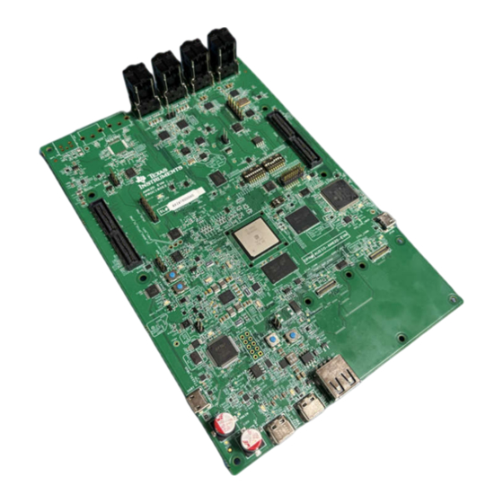
- Page 7 2 Hardware 2.1 Additional Images This section shows the AM62D Audio EVM images and location of various blocks on the board. Figure 2-1. AM62D Audio EVM Top Side SPRUJG2 – DECEMBER 2024 Submit Document Feedback Copyright © 2024 Texas Instruments Incorporated...
- Page 8 The AM62D Audio EVM is a high performance, standalone development platform that enables users to evaluate and develop audio applications for the AM62D System-on-Chip (SoC) from Texas Instruments. The following sections discuss the key features of the AM62D Audio EVM.
- Page 9 The PD IC uses a SPI EEPROM to load the necessary configuration on power up so it can negotiate a power contract with a compatible power source. SPRUJG2 – DECEMBER 2024 Submit Document Feedback Copyright © 2024 Texas Instruments Incorporated...
- Page 10 Buffer ICs to cater for alternate pin functionality. The output of the buffer is connected to the boot mode pins on the AM62D SoC and the output is enabled only when the boot mode is needed during a reset cycle. SPRUJG2 – DECEMBER 2024 Submit Document Feedback Copyright © 2024 Texas Instruments Incorporated...
- Page 11 Table 2-5. Boot Device Selection BOOTMODE [6:3] SW2.7 SW2.6 SW2.5 SW2.4 Primary Boot Device Selected Serial NAND OSPI QSPI Ethernet RGMII Ethernet RMII UART MMC/SD card eMMC SPRUJG2 – DECEMBER 2024 Submit Document Feedback Copyright © 2024 Texas Instruments Incorporated...
- Page 12 User Test LEDs and the associated GPIOs used to control it. Table 2-8. User Test LEDs Sl # GPIO used SCH Net Names GPIO1_49 SOC_GPIO1_49 LD10 U21.24(P27) IO_EXP_TEST_LED SPRUJG2 – DECEMBER 2024 Submit Document Feedback Copyright © 2024 Texas Instruments Incorporated...
- Page 13 0.85V VDDR_CORE TP60 0.85V VCC1V8_SYS TP86 1.8V VDDA_1V8 TP79 1.8V VDD_LPDDR4 TP81 1.1V VDD_MMC1_SD TP21 3.3V VCC_5V0 TP103 VDD_CANUART TP52 0.85V VDDSHV_SDIO TP35 3.3V VPP_1V8 TP69 1.8V SPRUJG2 – DECEMBER 2024 Submit Document Feedback Copyright © 2024 Texas Instruments Incorporated...
- Page 14 The device is provided with an analog supply of 3.3V and digital core supply of 1.8V. The TAD5212 configuration are supported through I2C interface. (SoC_I2C0) The I2C addresses of the TAD5212 devices are 0x50, 0x51, SPRUJG2 – DECEMBER 2024 Submit Document Feedback Copyright © 2024 Texas Instruments Incorporated...
- Page 15 Reset: The reset for the PCM6240 is connected to a circuit that ANDs the RESETSTATz from the AM62D SoC with the signal GPIO_PCM_RST from the I/O expander. A pull-up resistor is provided on PCM_RSTn to set the default active state. SPRUJG2 – DECEMBER 2024 Submit Document Feedback Copyright © 2024 Texas Instruments Incorporated...
- Page 16 20-pin JTAG connector is sensed using an auto presence detect circuit, the mux routes the 20-pin signals from the cTI connector to the AM62D SoC in place of the on-board emulation circuit. SPRUJG2 – DECEMBER 2024 Submit Document Feedback Copyright © 2024 Texas Instruments Incorporated...
- Page 17 ESD pulses up to ±15kV Human-Body Model (HBM) as specified in IEC 61000-4-2 and provides ±8kV contact discharge and ±12kV air-gap discharge. Table 2-11. JTAG Connector (J14) Pinout Pin No. Signal JTAG_TMS JTAG_TRST# JTAG_TDI JTAG_TDIS VCC_3V3_SYS JTAG_TDO SEL_XDS110_INV JTAG_cTI_RTCK DGND JTAG_cTI_TCK DGND JTAG_EMU0 SPRUJG2 – DECEMBER 2024 Submit Document Feedback Copyright © 2024 Texas Instruments Incorporated...
- Page 18 FTDI's web site. The FT_PROG is also used for programming the board serial number for users to identify the connected COM port with board serial number when one or more boards are connected to the computer. SPRUJG2 – DECEMBER 2024 Submit Document Feedback Copyright © 2024 Texas Instruments Incorporated...
- Page 19 A common mode choke of manufacturer part number DLW21SZ900HQ2B is provided on USB Data lines for EMI/EMC reduction. Along with ESD Protection IC manufacturer part number TPD4S012DRYR to suppress any transient voltages. SPRUJG2 – DECEMBER 2024 Submit Document Feedback Copyright © 2024 Texas Instruments Incorporated...
- Page 20 USB2.0 DP/DM signals. An ESD protection device of part number TPD1E01B04DPLT is included on CC signals and TVS2200DRVR IC is included on VBUS rail of Type-C Connector J25 to dissipate ESD strikes. SPRUJG2 – DECEMBER 2024 Submit Document Feedback Copyright © 2024 Texas Instruments Incorporated...
- Page 21 3.3V supply voltage. The SoC CAN data transmit data input is mapped to TXD of the transceiver and the CAN receive data output of the transceiver is mapped to the RXD of the SoC. SPRUJG2 – DECEMBER 2024 Submit Document Feedback Copyright © 2024 Texas Instruments Incorporated...
- Page 22 1.1V supply output from the PMIC. LPDDR4 reset (Active low) controlled by the AM62D SoC is pulled down to set the default active state. The provision for mounting a pull up resistor is also provided. SPRUJG2 – DECEMBER 2024 Submit Document Feedback Copyright © 2024 Texas Instruments Incorporated...
- Page 23 Power: Both VCC and VCCQ pins of the OSPI Flash memory is supplied through an on board 1.8V system power. The OSPI I/O group is powered by the VDDSHV1 domain of SoC and is also connected to 1.8V system power. SPRUJG2 – DECEMBER 2024 Submit Document Feedback Copyright © 2024 Texas Instruments Incorporated...
- Page 24 The External Reset is provided by ANDing RESETSTATz from SoC and a GPIO from I/O Expander. A pull up is provided on GPIO pin to set the default active state. SPRUJG2 – DECEMBER 2024 Submit Document Feedback Copyright © 2024 Texas Instruments Incorporated...
- Page 25 An ESD protection device of part number TPD6E001RSE is provided for data, clock, and command signals. TPD6E001RSE is a line termination device with integrated TVS diodes providing system-level IEC 61000-4-2 ESD protection, ±8kV contact discharge and ±15kV air-gap discharge. SPRUJG2 – DECEMBER 2024 Submit Document Feedback Copyright © 2024 Texas Instruments Incorporated...
- Page 26 A2 pin to high and A1, A0 pins to LOW. The first 259 bytes of memory are preprogrammed with identification information for each board. The remaining 65277 bytes are available to the user for data or code storage. SPRUJG2 – DECEMBER 2024 Submit Document Feedback Copyright © 2024 Texas Instruments Incorporated...
- Page 27 Automotive PHY MDI lines terminate to an Auto grade MATEnet ™ connector. The CPSW_RGMII1 and CPSW_RGMII2 Ports share a common MDIO Bus to communicate with the external PHY Transceiver. SPRUJG2 – DECEMBER 2024 Submit Document Feedback Copyright © 2024 Texas Instruments Incorporated...
- Page 28 DF40C-50DP-0.4V. This provides a flexibility of plugging in either an Industrial Grade Ethernet daughter card or an Automotive Grade Ethernet daughter card. The details of these are captured in the design documents of the respective cards. SPRUJG2 – DECEMBER 2024 Submit Document Feedback Copyright © 2024 Texas Instruments Incorporated...
- Page 29 CPLD 2 Interrupt signal CPLD1_DONE INPUT CPLD1 Programming Indication CPLD1_INTN INPUT CPLD 1 Interrupt signal USB_TYPEA_OC_INDICATI INPUT Type A Overcurrent Indication PCM1_INT INPUT PCM6240 Audio device 1 Interrupt signal SPRUJG2 – DECEMBER 2024 Submit Document Feedback Copyright © 2024 Texas Instruments Incorporated...
- Page 30 SoC_DVDD1V8 Connector 1 MCASP Header EXP1_GPIO0_3 GPIO GPIO0_33 GPMC0_OEN_R VDDSHV3 SoC_DVDD1V8 Audio Expansion Connector 1 MCASP Header EXP1_GPIO0_3 GPIO GPIO0_34 GPMC0_WEN VDDSHV3 SoC_DVDD1V8 Audio Expansion Connector 1 SPRUJG2 – DECEMBER 2024 Submit Document Feedback Copyright © 2024 Texas Instruments Incorporated...
- Page 31 HDMI_INTn INTERRUPT IO EXPANDER- INPUT HIGH VCC_3V3_SYS TEST GPIO2 from Test TEST_GPIO2 GPIO IO EXPANDER- HIGH VCC_3V3_SYS Automation Connector GPIO_PCM2_RST PCM6240_RST ENABLE IO EXPANDER- OUTPUT HIGH VCC_3V3_SYS SPRUJG2 – DECEMBER 2024 Submit Document Feedback Copyright © 2024 Texas Instruments Incorporated...
- Page 32 >= 15W. This logic enables the load switch TPS22810 for VMAIN supply. This VMAIN which is supplied to on board Buck-Boost and Buck regulators to generate fixed 5V and 3.3V supply for the EVM board. SPRUJG2 – DECEMBER 2024 Submit Document Feedback Copyright © 2024 Texas Instruments Incorporated...
- Page 33 Figure 2-19 shows the various discrete regulators, PMIC and LDOs used to generate power rails and the current consumption of each peripheral on the AM62D Audio EVM board. SPRUJG2 – DECEMBER 2024 Submit Document Feedback Copyright © 2024 Texas Instruments Incorporated...
- Page 34 AM62D Audio EVM Board power resources. The 3.3V supply generated from the Buck regulator LM5141-Q1 is the input supply to the PMIC, various SOC regulators and LDOs. The 5V supply generated from SPRUJG2 – DECEMBER 2024 Submit Document Feedback Copyright © 2024 Texas Instruments Incorporated...
- Page 35 Table 2-16. SoC Power Supply Sl.No Power Supply SoC Supply Rails I/O Power Group Voltage VDDA_CORE_USB VDDA_CORE_CSI VDD_CORE 0.75/ 0.85 VDD_CANUART CANUART VDD_CORE CORE VDDR_CORE VDDR_CORE CORE 0.75 SPRUJG2 – DECEMBER 2024 Submit Document Feedback Copyright © 2024 Texas Instruments Incorporated...
- Page 36 10mΩ± 1% VCC1V1 VDD_LPDDR4 E1 revision: 0x47 1mΩ± 1% E2 revision: 0x44 2.8 Clocking The Clock architecture of the AM62D Audio EVM is shown in Figure 2-21. SPRUJG2 – DECEMBER 2024 Submit Document Feedback Copyright © 2024 Texas Instruments Incorporated...
- Page 37 Gigabit Ethernet PHYs. There is one external crystal (32.768KHz) attached to the AM62D SoC to provide clock to its WKUP domain. SPRUJG2 – DECEMBER 2024 Submit Document Feedback Copyright © 2024 Texas Instruments Incorporated...
- Page 38 MCU_PORz is the MCU domain power ON/ Cold Reset input • MCU_RESETSTATz is the MCU domain warm reset status output Upon Power on Reset, all peripheral devices connected to the MAIN domain get reset by RESETSTATz. SPRUJG2 – DECEMBER 2024 Submit Document Feedback Copyright © 2024 Texas Instruments Incorporated...
- Page 39 The CPLD requires 3.3V for Core (VCC) and VCCIO0 and 1.8V for other I/Os (VCCIO1, VCCIO2 & VCCIO3). 2x 1x6 HDR manufacturer part number 61300611121 are installed for JTAG programming. SPRUJG2 – DECEMBER 2024 Submit Document Feedback Copyright © 2024 Texas Instruments Incorporated...
- Page 40 Hardware www.ti.com Figure 2-24. CPLD1 Block Diagram SPRUJG2 – DECEMBER 2024 Submit Document Feedback Copyright © 2024 Texas Instruments Incorporated...
- Page 41 Hardware Figure 2-25. CPLD2 Block Diagram The current AM62D Audio EVM has CPLD mapping as shown below. CPLD1 Configuration E1 SPRUJG2 – DECEMBER 2024 Submit Document Feedback Copyright © 2024 Texas Instruments Incorporated...
- Page 42 Hardware www.ti.com CPLD1 Configuration E1 Figure 2-26. CPLD1 Pin Mapping CPLD2 Configuration E1 SPRUJG2 – DECEMBER 2024 Submit Document Feedback Copyright © 2024 Texas Instruments Incorporated...
- Page 43 CPLD2 Configuration E1 Figure 2-27. CPLD2 Pin Mapping 2.11 Audio Expansion Connectors (Headers) The AM62D Audio EVM features two Audio expansion connectors, and each connector comprises of 80 pins. SPRUJG2 – DECEMBER 2024 Submit Document Feedback Copyright © 2024 Texas Instruments Incorporated...
- Page 44 Table 2-19. Audio Expansion Connector 1 Pinout SOC BALL NET NAME PORz_OUT_1V8 VCC_5V0 MCU_TIMER_IO1_1V8 VCC_5V0 MCU_TIMER_IO2_1V8 VCC_5V0 EXP1_TIMESTAMP0_IN VCC1V8_SYS EXP1_TIMESTAMP1_IN VCC1V8_SYS MCU_SPI0_CLK_1V8 EXP1_I2C2_SCL MCU_SPI0_D0_1V8 EXP1_I2C2_SDA MCU_SPI0_D1_1V8 MCU_SPI0_CS0_1V8 EXP1_GPIO0_1 EXP1_McASP1_AXR0 EXP1_McASP1_AXR2 EXP1_McASP1_AXR1 EXP1_McASP1_AXR3 SPRUJG2 – DECEMBER 2024 Submit Document Feedback Copyright © 2024 Texas Instruments Incorporated...
- Page 45 SOC BALL NET NAME EXP1_GPIO0_13 CPLD EXP1_CLK_IN EXP1_GPIO0_14 EXP1_McASP1_ACLKX EXP1_GPIO0_31 CPLD_McASP1_AFSX EXP1_GPIO0_32 CPLD_McASP1_AFSR EXP1_GPIO0_33 EXP1_McASP1_ACLKR EXP1_GPIO0_34 EXP1_CLK_OUT EXP1_GPIO0_37 EXP1_GPIO0_35 EXP1_GPIO0_38 UART5_TXD UART5_RXD CPLD/EXP1_McASP0_AXR0 EXP1_McASP0_AXR1 EXP1_McASP0_AXR2 EXP1_McASP0_AXR3 EXP1_McASP0_ACLKX SPRUJG2 – DECEMBER 2024 Submit Document Feedback Copyright © 2024 Texas Instruments Incorporated...
- Page 46 Table 2-20. Audio Expansion Connector 2 Pinout SOC BALL NET NAME PORz_OUT_1V8 VCC_5V0 EXP2_EHRPWM0_A VCC_5V0 EXP2_EHRPWM1_A VCC_5V0 EXP2_TIMESTAMP0_IN VCC1V8_SYS EXP2_TIMESTAMP1_IN VCC1V8_SYS MCU_SPI1_CLK_1V8 SoC_I2C1_SCL MCU_SPI1_D0_1V8 SoC_I2C1_SDA MCU_SPI1_D1_1V8 MCU_SPI1_CS0_1V8 EXP2_MCU_SPI1_CS2_1V8 CPLD/EXP2_McASP2_AXR0 SPRUJG2 – DECEMBER 2024 Submit Document Feedback Copyright © 2024 Texas Instruments Incorporated...
- Page 47 CPLD/EXP2_McASP2_AXR1 CPLD/EXP2_McASP2_AXR4 EXP2_McASP2_AXR5 CPLD EXP2_CLK_IN EXP2_McASP2_AXR6 CPLD/EXP2_McASP2_ACLKX EXP2_McASP2_AXR7 CPLD/EXP2_McASP2_AFSX EXP2_McASP2_AXR8 CPLD/EXP2_McASP2_AFSR EXP2_GPIO0_45 CPLD/EXP2_McASP2_ACLKR EXP2_GPIO0_46 EXP2_CLK_OUT EXP2_GPIO0_47 TIMER_IO7 EXP2_GPIO0_48 UART6_TXD UART6_RXD EXP2_McASP2_AXR9 EXP2_McASP2_AXR13 EXP2_McASP2_AXR10 CPLD/EXP2_McASP2_AXR14 EXP2_McASP2_AXR11 CPLD/EXP2_McASP2_AXR15 EXP2_McASP2_AXR12 SPRUJG2 – DECEMBER 2024 Submit Document Feedback Copyright © 2024 Texas Instruments Incorporated...
- Page 48 MCU I2C0 & WKUP_I2C0 Interface: MCU I2C[0] and WKUP_I2C[0] is connected PMIC. Figure 2-28 depicts the I2C tree, and Table 2-22 provides the complete I2C address mapping details present on the AM62D Audio EVM. SPRUJG2 – DECEMBER 2024 Submit Document Feedback Copyright © 2024 Texas Instruments Incorporated...
- Page 49 SoC_I2C0 GPIO Port Expander 2 TCA6416ARTWR 0x20 SoC_I2C0 CPLD LCMXO2-256HC-4SG48I Can be Programmed SoC_I2C1 Audio Expansion Connector 2 <connector interface> SoC_I2C2 Audio Expansion Connector 1 <connector interface> SPRUJG2 – DECEMBER 2024 Submit Document Feedback Copyright © 2024 Texas Instruments Incorporated...
- Page 50 Table 2-22. I2C Mapping Table (continued) I2C Port Device/Function Part Number I2C Address MCU_I2C0 PMIC PTPS6522430RAHRQ1 0x48,0x49,0x4A, 0x4B WKUP_I2C0 Others BOOTMODE_I2C I2C Bootmode Buffer TCA6424ARGJR 0x22 SPRUJG2 – DECEMBER 2024 Submit Document Feedback Copyright © 2024 Texas Instruments Incorporated...
- Page 51 3 Hardware Design Files The hardware design files such as schematics, BOM, PCB Layout, Assembly Files and Gerber files are available in the link below. Design Files SPRUJG2 – DECEMBER 2024 Submit Document Feedback Copyright © 2024 Texas Instruments Incorporated...
- Page 52 ESD mats when interfacing with the product. The product is used in the basic electromagnetic environment as in laboratory conditions, and the applied standard is as per EN IEC 61326-1:2021. SPRUJG2 – DECEMBER 2024 Submit Document Feedback Copyright © 2024 Texas Instruments Incorporated...
- Page 53 This section describes the currently known issues on each EVM revision and applicable workarounds. Issues that have been patched have modification labels attached to the EVM assembly. 5.2 Trademarks Code Composer Studio ™ is a trademark of Texas Instruments. MATEnet ™ is a trademark of TE Connectivity. ®...
- Page 54 STANDARD TERMS FOR EVALUATION MODULES Delivery: TI delivers TI evaluation boards, kits, or modules, including any accompanying demonstration software, components, and/or documentation which may be provided together or separately (collectively, an “EVM” or “EVMs”) to the User (“User”) in accordance with the terms set forth herein.
- Page 55 www.ti.com Regulatory Notices: 3.1 United States 3.1.1 Notice applicable to EVMs not FCC-Approved: FCC NOTICE: This kit is designed to allow product developers to evaluate electronic components, circuitry, or software associated with the kit to determine whether to incorporate such items in a finished product and software developers to write software applications for use with the end product.
- Page 56 www.ti.com Concernant les EVMs avec antennes détachables Conformément à la réglementation d'Industrie Canada, le présent émetteur radio peut fonctionner avec une antenne d'un type et d'un gain maximal (ou inférieur) approuvé pour l'émetteur par Industrie Canada. Dans le but de réduire les risques de brouillage radioélectrique à...
- Page 57 www.ti.com EVM Use Restrictions and Warnings: 4.1 EVMS ARE NOT FOR USE IN FUNCTIONAL SAFETY AND/OR SAFETY CRITICAL EVALUATIONS, INCLUDING BUT NOT LIMITED TO EVALUATIONS OF LIFE SUPPORT APPLICATIONS. 4.2 User must read and apply the user guide and other available documentation provided by TI regarding the EVM prior to handling or using the EVM, including without limitation any warning or restriction notices.
- Page 58 Notwithstanding the foregoing, any judgment may be enforced in any United States or foreign court, and TI may seek injunctive relief in any United States or foreign court. Mailing Address: Texas Instruments, Post Office Box 655303, Dallas, Texas 75265 Copyright © 2023, Texas Instruments Incorporated...
- Page 59 TI products. TI’s provision of these resources does not expand or otherwise alter TI’s applicable warranties or warranty disclaimers for TI products. TI objects to and rejects any additional or different terms you may have proposed. IMPORTANT NOTICE Mailing Address: Texas Instruments, Post Office Box 655303, Dallas, Texas 75265 Copyright © 2024, Texas Instruments Incorporated...
Need help?
Do you have a question about the AUDIO-AM62D-EVM and is the answer not in the manual?
Questions and answers