Advertisement
Quick Links
Advertisement

Related Manuals for Baumer CH50I.M12


Summary of Contents for Baumer CH50I.M12
- Page 1 Operating Manual CH50I.M12 EN-US IO-Link Hub...
- Page 2 Indicates a danger with low risk, which could lead to light or medium injury if not avoided. NOTE Indicates a warning of material damage. INFO Indicates practical information and tips that enable optimal use of the devices. Operating Manual CH50I.M12 | V1...
- Page 3 The present documentation uses the trademarks of the following companies and institutions: IO-Link c/o PROFIBUS User Organisation e.V. (PNO) Specifications Specification Link IO-Link www.io-link.com Version 1.1.2 of 07.2013 INFO The features of IO-Link specification V 1.1.3 are supported. V1 | CH50I.M12 Operating Manual...
- Page 4 Used electrical and electronic devices may not be disposed of in household waste. The product contains valuable raw materials that can be recycled. There- fore dispose of this product at the appropriate collection point. For additional in- formation visit www.baumer.com. Operating Manual CH50I.M12 | V1...
- Page 5 At all times, the instruction manual must be made available to the operator at the machine the device is operated at. INFO Any manipulation/modification of hardware and software only qualified Baumer personnel, ex- cept for firmware updates. Intended use The device has been designed and manufactured for: Industrial use.
- Page 6 Any safety functions in the system are not ensured. only use the device in environments with corresponding IP-rating. only clean the device with oil-free compressed air and a leather cloth. do not use the device as a climbing aid. Operating Manual CH50I.M12 | V1...
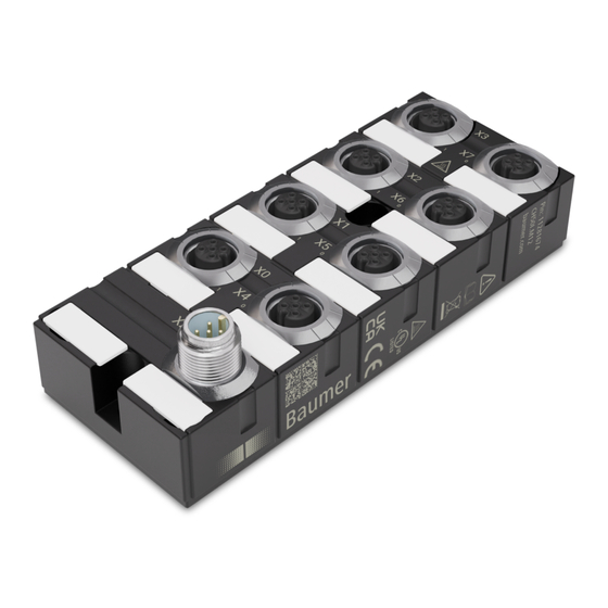
- Page 7 Baumer Description Description Device IO-Link hub (CH50I.M12) IO-Link hub in 50 mm plastic housing 1 x M12 IO-Link Class A 8 x M12 I/O 16 configurable digital inputs/outputs Product name nomenclature The nomenclature is based on a scheme indicating the product functionality.
- Page 8 Pin 3 0 V US (L-) Pin 4 C/Q IO-Link Pin 5 n.c. X0 ... X7 (mating M12) Pin 1 24 V US (L+) Pin 2 DIO US Pin 3 0 V US Pin 4 DIO US Pin 5 Operating Manual CH50I.M12 | V1...
- Page 9 4 bytes (inputs), 2 bytes (out- puts) Sensor supply + Terminal/mating Operating voltage 24 V DC Power supply Per port ≤0.5 A Input (DI) Terminal/mating Conductor cross-section ≤0.75 mm² Cable length ≤30 m Input characteristic EN 61131-2 Type 1 + Type 3 V1 | CH50I.M12 Operating Manual...
- Page 10 IP68 sidered in UL approval Protection rating Level of contamination EMC emission Radiated interference E-field EN 61000-6-4 Emission QP: 40 dBμ V/m @ 30 ... 230 QP: 47 dBμ V/m @ 230 ... 1000 MHz Operating Manual CH50I.M12 | V1...
- Page 11 Internal Suppressor diode Product reliability Product reliability MTTF SN 29500 (at 40 °C and rated 57 years data) Mechanical data Mounting data Weight 200 g Dimensions L x W x H 126 x 50 x 34,5 mm V1 | CH50I.M12 Operating Manual...
- Page 12 Programmable Logic Con- trollers Part 2 2014/30/EU Compliant 2011/65/EU UKCA Compliant 2014/30/EU Compliant REACH No. 1907/2006 SVHC List WEEE 2012/19/EU Compliant ULus E201820 RoHS 2011/65/EU & 2015/863 Exception 6c&7a China RoHS SJ/T 11364-2014 25 EPUP Operating Manual CH50I.M12 | V1...
- Page 13 Sufficient space to ease replacement and plug-in connections Appropriate installation site in terms of vibration and shock, temperature and humidity (see chapter Technical Specifications) Protected site to prevent connection cables from being torn off accidentally Diagnostic LEDs visible during operation Dimensions V1 | CH50I.M12 Operating Manual...
- Page 14 Functional ground For EMC compliance, a ring cable lug is required. Input and output shield connection of is via the ring cable lug. Ill. 3: Fastening the ring cable lug Also see about this 2 Accessories [} 33] Operating Manual CH50I.M12 | V1...
- Page 15 Use a conductive screw to fasten the ring cable lug. c) Slightly tighten the first M4 screw. d) Slightly tighten the second M4 screw. e) Tighten both M4 screws to the specified torque. Also see about this 2 Functional ground [} 14] V1 | CH50I.M12 Operating Manual...
- Page 16 Risk of fire due to short circuit. Supply lines and/or devices may short circuit when damaged causing overheating and fire. a) Provide intelligent current monitoring or fuse. INFO Maximum length of sensor and actuator cables is limited to 30 m. Operating Manual CH50I.M12 | V1...
- Page 17 Risk of personal injury and material damage due to failure caused by ingress of conductive liq- uids. a) Seal any male and female connectors not in use. Ill. 5: Connection lines 0.6 Nm CAM12- W13-11238690 INFO A large selection of connection cables can be found on the Baumer website https:// www.baumer.com. V1 | CH50I.M12 Operating Manual...
- Page 18 IO-Link in status OPERATE, cyclical data com- Green munication; sensor supply OK On continuous Short circuit DO, temperature warning etc. Flashing at 1 Hz IO-Link communication error Device off, no IO-Link connection present Tab. 1: Indicator IO-Link and US Operating Manual CH50I.M12 | V1...
- Page 19 Tab. 3: LED indicator digital inputs/outputs Error at input or output In the event of error (short circuit, overload or power recovery) present at minimum one input or output, the LEDs of all input and output slots light up red. V1 | CH50I.M12 Operating Manual...
- Page 20 0x0015 SerialNumber Consecutive serial num- ber, set by default 0x0016 HardwareRevision e.g. B. "01.00" 0x0017 FirmwareRevision e.g. "V.1.00.00" 0x0018 ApplicationSpecific-Tag 16 ... 32 User-specific name, e.g. "System 3 / Port 4" 0x0019 FunctionTag 0x001A LocationTag Operating Manual CH50I.M12 | V1...
- Page 21 Allows you to read a short circuit being – Detection DO present at a specific channel. Subindex 1: X0 Pin 4 Subindex 2: X0 Pin 2 Subindex 15: X7 Pin 4 Subindex 16: X7 Pin 2 V1 | CH50I.M12 Operating Manual...
- Page 22 Configuration Subindex 1: X0 Pin 4 Subindex 2: X0 Pin 2 Subindex 15: X7 Pin 4 Subindex 16: X7 Pin 2 Setting per channel (subindex): 0 = Auto configuration / universal (DIO) 1 = Input Operating Manual CH50I.M12 | V1...
- Page 23 0 = OFF (no filtering) 1 = 1 μs 2 = 10 μs 3 = 100 μs 4 = 1 ms 5 = 2 ms 6 = 3 ms 7 = 5 ms 8 = 10 ms V1 | CH50I.M12 Operating Manual...
- Page 24 Subindex 2: X0 Pin 2 Subindex 15: X7 Pin 4 Subindex 16: X7 Pin 2 Setting per channel (subindex): 0 = logical 0 / OFF 1 = logical 1 / ON 2 = Hold last state Operating Manual CH50I.M12 | V1...
- Page 25 Channel A Channel B Pin4_X0 Pin4_X0 Pin4_X1 Pin2_X0 Pin4_X2 Pin4_X1 Pin4_X3 Pin2_X1 Pin4_X4 Pin4_X2 Pin4_X5 Pin2_X2 Pin4_X6 Pin4_X3 Pin4_X7 Pin2_X3 Pin2_X0 Pin4_X4 Pin2_X1 Pin2_X4 Pin2_X2 Pin4_X5 Pin2_X3 Pin2_X5 Pin2_X4 Pin4_X6 Pin2_X5 Pin2_X6 Pin2_X6 Pin4_X7 Pin2_X7 Pin2_X7 V1 | CH50I.M12 Operating Manual...
- Page 26 Overload/short circuit at DIO pin - port 3 Check installation pin 4 0x8CA7 Error Overload/short circuit at DIO pin - port 3 Check installation pin 2 0x8CA8 Error Overload/short circuit at DIO pin - port 4 Check installation pin 4 Operating Manual CH50I.M12 | V1...
- Page 27 Port 5 Pin 1 0x8CD6 Error Overload/short circuit in sensor supply at Check installation Port 6 Pin 1 0x8CD7 Error Overload/short circuit in sensor supply at Check installation Port 7 Pin 1 Tab. 4: IO-Link events V1 | CH50I.M12 Operating Manual...
- Page 28 Device temperature too high or too low Input/output error or warning (short circuit or overload) DIA at channel X 0 = channel 1 15 = channel 16 DIA at channel X 0 = channel 1 15 = channel 16 Operating Manual CH50I.M12 | V1...
- Page 29 1 ... 255 = ID value read from object Process data Digital outputs Byte 0 Inputs X0 ... X3 Contact Pin4_X0 Pin2_X0 Pin4_X1 Pin2_X1 Pin4_X2 Pin2_X2 Pin4_X3 Pin2_X3 Byte 1 Inputs X4 ... X7 Contact Pin4_X4 Pin2_X4 Pin4_X5 Pin2_X5 Pin4_X6 Pin2_X6 Pin4_X7 Pin2_X7 V1 | CH50I.M12 Operating Manual...
- Page 30 DIA at channel X 0 = channel 1 15 = channel 16 DIA at channel X 0 = channel 1 15 = channel 16 DIA at channel X 0 = channel 1 15 = channel 16 Operating Manual CH50I.M12 | V1...
- Page 31 1 ... 255 = ID value read from object Process data Digital outputs Byte 0 Inputs X0 ... X7 Contact Pin4_X0 Pin4_X1 Pin4_X2 Pin4_X3 Pin4_X4 Pin4_X5 Pin4_X6 Pin4_X7 Byte 1 Inputs X0 ... X7 Contact Pin2_X0 Pin2_X1 Pin2_X2 Pin2_X3 Pin2_X4 Pin2_X5 Pin2_X6 Pin2_X7 V1 | CH50I.M12 Operating Manual...
- Page 32 The function of the devices is not guaranteed. a) Replace defective or damaged devices. Cleaning the appliance: Only use oil-free compressed air or ethanol Only use non-fibrous materials (e.g. leather cloth) Do not use contact spray Operating Manual CH50I.M12 | V1...
- Page 33 10.1.1 Tools Designation Art. no. M8 installation wrench set SW 9 CAM8.WS9-11238649 M12 installation wrench set SW 13 CAM12-W13-11238690 Ill. 6: Assembly wrench INFO PRODUCTS AND ACCESSORIES You will encounter a large product selection at: https://www.baumer.com V1 | CH50I.M12 Operating Manual...
- Page 36 Baumer Germany GmbH & Co. KG Bodenseeallee 7 DE-78333 Stockach www.baumer.com...
Need help?
Do you have a question about the CH50I.M12 and is the answer not in the manual?
Questions and answers