Advertisement
Quick Links
Advertisement

Related Manuals for Baumer CC60I.AIM


Summary of Contents for Baumer CC60I.AIM
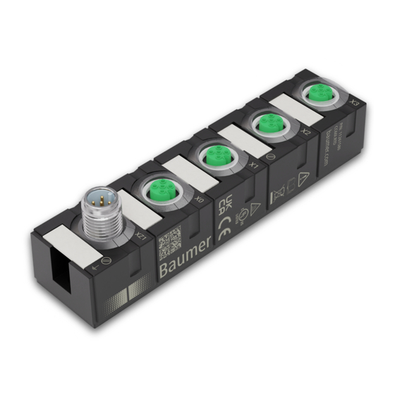
- Page 1 Operating Manual CC60I.AIM / CC60I.RTD EN-US IO-Link Hub...
- Page 2 Indicates a danger with low risk, which could lead to light or medium injury if not avoided. NOTE Indicates a warning of material damage. INFO Indicates practical information and tips that enable optimal use of the devices. Operating Manual CC60I.AIM / CC60I.RTD | V1...
- Page 3 The present documentation uses the trademarks of the following companies and institutions: IO-Link c/o PROFIBUS User Organisation e.V. (PNO) Specifications Specification Link IO-Link www.io-link.com Version 1.1.2 of 07.2013 INFO The features of IO-Link specification V 1.1.3 are supported. V1 | CC60I.AIM / CC60I.RTD Operating Manual...
- Page 4 Used electrical and electronic devices may not be disposed of in household waste. The product contains valuable raw materials that can be recycled. There- fore dispose of this product at the appropriate collection point. For additional in- formation visit www.baumer.com. Operating Manual CC60I.AIM / CC60I.RTD | V1...
- Page 5 At all times, the instruction manual must be made available to the operator at the machine the device is operated at. INFO Any manipulation/modification of hardware and software only qualified Baumer personnel, ex- cept for firmware updates. Intended use The device has been designed and manufactured for: Industrial use.
- Page 6 Any safety functions in the system are not ensured. only use the device in environments with corresponding IP-rating. only clean the device with oil-free compressed air and a leather cloth. do not use the device as a climbing aid. Operating Manual CC60I.AIM / CC60I.RTD | V1...
- Page 7 1 x M12 IO-Link Class A 4 x M12 AI Multi (U/I) IO-Link Hub (CC60I.RTD) IO-Link hub for resistance temperature de- tectors (RTD) 30 mm plastic housing 1 x M12 IO-Link Class A 4 x M12 AI RTD V1 | CC60I.AIM / CC60I.RTD Operating Manual...
- Page 8 Pin 3 0 V US (L-) Pin 4 C/Q IO-Link Pin 5 n.c. X0 ... X3 (mating M12) Pin 1 24 V US Pin 2 Pin 3 0 V US Pin 4 n.c. Pin 5 n.c. Operating Manual CC60I.AIM / CC60I.RTD | V1...
- Page 9 Pin 3 0 V US (L-) Pin 4 C/Q IO-Link Pin 5 n.c. X0 ... X7 (mating M12) Pin 1 Pin 2 CH S+ Pin 3 Pin 4 CH S- Pin 5 n.c. V1 | CC60I.AIM / CC60I.RTD Operating Manual...
- Page 10 Resolution 24 Bit Filter Interference frequency filter Off, 50/60 Hz Conversion time Interference frequency filter Off 2 ms Interference frequency filter Off 12 ms Interference frequency filter 240 ms 50/60 Hz (-95 dB) Operating Manual CC60I.AIM / CC60I.RTD | V1...
- Page 11 <0.4 % Drift 60 ppm/K Nominal measuring range 4 ... 20V Range of overdrive 1.19 ... 22.81 mA Resolution 578.70 nA Measuring accuracy At 25 °C (full deflection) <0.4 % Drift 60 ppm/K V1 | CC60I.AIM / CC60I.RTD Operating Manual...
- Page 12 (burst) ±1 kV AIN (5 kHz, 100 kHz) DC inputs/outputs Magnetic field EN 61000-4-8 30 A/m @ 50 Hz Variables of conducted distur- EN 61000-4-6, irregular 10 V bance, HF fields Operating Manual CC60I.AIM / CC60I.RTD | V1...
- Page 13 216 years data) 5.1.6 Mechanical data Material data Housing material Valox 553 black Flame resistance IEC 60695-2-1 Mounting data Weight 150 g Dimensions L x W x H 126 x 29.78 x 34.3 mm V1 | CC60I.AIM / CC60I.RTD Operating Manual...
- Page 14 Programmable Logic Con- trollers Part 2 2014/30/EU Compliant 2011/65/EU UKCA Compliant 2014/30/EU Compliant REACH No. 1907/2006 SVHC List WEEE 2012/19/EU Compliant ULus E201820 RoHS 2011/65/EU & 2015/863 Exception 6c&7a China RoHS SJ/T 11364-2014 25 EPUP Operating Manual CC60I.AIM / CC60I.RTD | V1...
- Page 15 Sensor current ca. 250 μA Transformation principle Sigma-Delta Resolution 24 Bit Conversion time Interference frequency filter Off 12 ms Interference frequency filter Off 50 ms Interference frequency filter 120 ms 50/60 Hz (-95 dB) V1 | CC60I.AIM / CC60I.RTD Operating Manual...
- Page 16 Relative humidity ≤95 % Mechanical Oscillation test EN 60068 Part 2-6 5 ... 500 Hz; constant ampli- tude 1 mm; acceleration 15 g Shock test EN 60068 Part 2-27 50 g, duration 11 ms Operating Manual CC60I.AIM / CC60I.RTD | V1...
- Page 17 Overvoltage protection Overload protection device To be ensured by load circuit supply monitoring Inverse-polarity protection de- vice supply 5.2.5 Product reliability Product reliability MTTF SN 29500 (at 40 °C and rated 216 years data) V1 | CC60I.AIM / CC60I.RTD Operating Manual...
- Page 18 Programmable Logic Con- trollers Part 2 2014/30/EU Compliant 2011/65/EU UKCA Compliant 2014/30/EU Compliant REACH No. 1907/2006 SVHC List WEEE 2012/19/EU Compliant ULus E201820 RoHS 2011/65/EU & 2015/863 Exception 6c&7a China RoHS SJ/T 11364-2014 25 EPUP Operating Manual CC60I.AIM / CC60I.RTD | V1...
- Page 19 Appropriate installation site in terms of vibration and shock, temperature and humidity (see chapter Technical Specifications) Protected site to prevent connection cables from being torn off accidentally Diagnostic LEDs visible during operation Dimensions Ill. 1: Dimensions in mm V1 | CC60I.AIM / CC60I.RTD Operating Manual...
- Page 20 For EMC compliance, a ring cable lug is required. Input and output shield connection of is via the ring cable lug. Ill. 3: Fastening the ring cable lug Also see about this 2 Accessories [} 49] Operating Manual CC60I.AIM / CC60I.RTD | V1...
- Page 21 Use a conductive screw to fasten the ring cable lug. c) Slightly tighten the first M4 screw. d) Slightly tighten the second M4 screw. e) Tighten both M4 screws to the specified torque. Also see about this 2 Functional ground [} 20] V1 | CC60I.AIM / CC60I.RTD Operating Manual...
- Page 22 Supply lines and/or devices may short circuit when damaged causing overheating and fire. a) Provide intelligent current monitoring or fuse. INFO Maximum length of sensor and actuator cables is limited to 30 m. Operating Manual CC60I.AIM / CC60I.RTD | V1...
- Page 23 Risk of personal injury and material damage due to failure caused by ingress of conductive liq- uids. a) Seal any male and female connectors not in use. Ill. 5: Connection lines 0.6 Nm 11238694 INFO A large selection of connection cables can be found on the Baumer website https:// www.baumer.com. V1 | CC60I.AIM / CC60I.RTD Operating Manual...
- Page 24 Flashing at 1 Hz IO-Link in status OPERATE, cyclical data com- Green munication; sensor supply OK Flashing at 1 Hz Error/warning Device off, no IO-Link connection present Tab. 1: Indicator IO-Link and US Operating Manual CC60I.AIM / CC60I.RTD | V1...
- Page 25 Error at input or output In the event of error (short circuit, overload or power recovery) present at minimum one input or output, the LEDs of all input and output slots light up red. V1 | CC60I.AIM / CC60I.RTD Operating Manual...
- Page 26 IOL/Analog 4-port verter, AI RTD Converter, Multi U/I 0x0015 SerialNumber Consecutive serial number, set by default 0x0016 HardwareRevision e.g. "01.00" 0x0017 FirmwareRevision e.g. "V.1.00.00" 0x0018 ApplicationSpecific- User-specific name, e.g. "System 3 / Port 4" Operating Manual CC60I.AIM / CC60I.RTD | V1...
- Page 27 -13 °F to +158 °F in incre- Value °F ments of 0.1 °F. Updated every 10 0x0060 Identification: Identification number for device 0x0000 Identification ID identification. Value is provided in the input process data. V1 | CC60I.AIM / CC60I.RTD Operating Manual...
- Page 28 TEMP - diagnosed high temperature TEMP - LED status R/W Minimum warning threshold Maximum warning threshold Cable break at sen- Below measuring range Measuring range exceeded Short circuit in power supply Total length in bytes Operating Manual CC60I.AIM / CC60I.RTD | V1...
- Page 29 Inputs: Lower Adjustable values: -32 768 warning -32 768 ... 32 767 threshold port Inputs: Lower warning threshold port Inputs: Lower warning threshold port Inputs: Lower warning threshold port Total length in bytes V1 | CC60I.AIM / CC60I.RTD Operating Manual...
- Page 30 Value is provided in the input process data. 0x0061 Identification: User User-defined serial number. It 0x0000 Defined Serial Num- may be used to ensure that the device will only be connected to an appropriate master. Operating Manual CC60I.AIM / CC60I.RTD | V1...
- Page 31 Baumer Operation Length in ISDU index Object name Access bytes Significance Default value 0x79 Data Format Motorola = 0x00 Intel = 0x01 0x7A Temperature Format R/W Celsius = 0x00 Fahrenheit = 0x01 V1 | CC60I.AIM / CC60I.RTD Operating Manual...
- Page 32 TEMP - diag- nosed high temperature TEMP - LED status Minimum warning threshold Maximum warning threshold Cable break at sensor Below measur- ing range Measuring range ex- ceeded Total length in bytes Operating Manual CC60I.AIM / CC60I.RTD | V1...
- Page 33 Inputs: Lower warning Adjustable values: -32 768 threshold port X0 -32 768 ... 32 767 Inputs: Lower warning threshold port X1 Inputs: Lower warning threshold port X2 Inputs: Lower warning threshold port X3 V1 | CC60I.AIM / CC60I.RTD Operating Manual...
- Page 34 Inputs: Lower Adjustable val- -32 768 warning ues: threshold port -32 768 ... 32 Inputs: Lower warning threshold port Inputs: Lower warning threshold port Inputs: Lower warning threshold port Total length in bytes Operating Manual CC60I.AIM / CC60I.RTD | V1...
- Page 35 Check installation Port 0 Pin 1 0x8CD1 Error Overload/short circuit in sensor supply at Check installation Port 1 Pin 1 0x8CD2 Error Overload/short circuit in sensor supply at Check installation Port 2 Pin 1 V1 | CC60I.AIM / CC60I.RTD Operating Manual...
- Page 36 - Port 1 0x8D42 Warning User-defined maximum warning threshold Check application exceeded - Port 2 0x8D43 Warning User-defined maximum warning threshold Check application exceeded - Port 3 Tab. 4: IO-Link events for CC60I.AIM Operating Manual CC60I.AIM / CC60I.RTD | V1...
- Page 37 Fallen below the user-defined warning Check application threshold - Port 0 0x8D31 Warning Fallen below the user-defined warning Check application threshold - Port 1 0x8D32 Warning Fallen below the user-defined warning Check application threshold - Port 2 V1 | CC60I.AIM / CC60I.RTD Operating Manual...
- Page 38 Diagnostics Pa- Channel MSB Channel Middle rameter Write Byte 8 Diagnostic tools Channel LSB Error or warning Device tempera- L+ (US) Overvolt- at input ture too high or age or undervolt- too low Operating Manual CC60I.AIM / CC60I.RTD | V1...
- Page 39 Nominal range 20736 5100 7.50 V 13824 3600 5.00 V 0001 361.7 μV 0000 0 uV FFFF -361.7 μV Range of un- derdrive -345 FEA7 >-0.1243 V Warning -4864 ED00 <-1.7593 V Underflow Error V1 | CC60I.AIM / CC60I.RTD Operating Manual...
- Page 40 Nominal range 20736 5100 3.75 V 13824 3600 2.5 V 0001 180.85 μV 0000 0 uV FFFF -180.85 μV Range of un- derdrive -345 FEA7 >-0.0621 V Warning -4864 ED00 <-0.8796 V Underflow Error Operating Manual CC60I.AIM / CC60I.RTD | V1...
- Page 41 20736 5100 15.0000 mA 13824 3600 10.0000 mA 0001 723 nA 0000 0 mA INFO At the analog input there are 0 ... 20 mA does not have an underflow range or underflow. V1 | CC60I.AIM / CC60I.RTD Operating Manual...
- Page 42 Overflow 10000 2710 1000.0 Range of overdrive 8501 2135 850.1 8500 2134 850.0 Nominal range 0001 0000 -2000 F830 -200.0 -2001 F82F -200.1 Range of underdrive -2200 F768 -220.0 -32768 8000 <-220.0 Underflow Operating Manual CC60I.AIM / CC60I.RTD | V1...
- Page 43 Underflow Resistor Digits in Measured value Dec. Hex. R in Ohm Area 32767 7FFF >3527.7 Overflow 32511 7EFF 3527.7 Range of overdrive 27649 6C01 3000.1 27648 6C00 3000.0 Nominal range 0001 0.1085 0000 V1 | CC60I.AIM / CC60I.RTD Operating Manual...
- Page 44 0b0001 - 0 ... 10 V 0b0010 - -10 ... 10 V 0b0011 - 0 ... 5 V 0b0100 - -5 ... 5 V 0b0101 - 0 ... 20 mA 0b0110 - 4 ... 20 mA Operating Manual CC60I.AIM / CC60I.RTD | V1...
- Page 45 0b0010 - Pt100 0b0011 - Pt200 0b0100 - Pt500 0b0101 - Pt1000 0b0110 - Ni100 0b0111 - Ni120 0b1000 - Ni200 0b1001 - Ni500 0b1010 - Ni1000 0b1011 - Resistance 0 ... 3 kΩ V1 | CC60I.AIM / CC60I.RTD Operating Manual...
- Page 46 0b0010 – Pt100 0b0011 – Pt200 0b0100 – Pt500 0b0101 – Pt1000 0b0110 – Ni100 0b0111 – Ni120 0b1000 – Ni200 0b1001 – Ni500 0b1010 – Ni1000 0b1011 - Resistance 0 ... 3 kΩ Operating Manual CC60I.AIM / CC60I.RTD | V1...
- Page 47 The same output process data cannot be two times in a row. Instead, change the process data command byte from 0xfc to another value such as 0x00 and then reset to 0xfc. Also see about this 2 IO-Link object directory [} 26] V1 | CC60I.AIM / CC60I.RTD Operating Manual...
- Page 48 The function of the devices is not guaranteed. a) Replace defective or damaged devices. Cleaning the appliance: Only use oil-free compressed air or ethanol Only use non-fibrous materials (e.g. leather cloth) Do not use contact spray Operating Manual CC60I.AIM / CC60I.RTD | V1...
- Page 49 Baumer Annex Annex 10.1 Accessories 10.1.1 Tools Designation Art. no. M12 installation wrench set SW 13 CAM12-W13-11238690 Ill. 6: Assembly wrench INFO PRODUCTS AND ACCESSORIES You will encounter a large product selection at: https://www.baumer.com V1 | CC60I.AIM / CC60I.RTD Operating Manual...
- Page 52 Baumer Germany GmbH & Co. KG Bodenseeallee 7 DE-78333 Stockach www.baumer.com...
Need help?
Do you have a question about the CC60I.AIM and is the answer not in the manual?
Questions and answers