
Subscribe to Our Youtube Channel
Related Manuals for raditeq PRO RadiSense RSS2018S


Summary of Contents for raditeq PRO RadiSense RSS2018S
- Page 1 Product Manual RadiSense ® Electric Field Probe Models: RSS2018S | RSS2026S RSS2040S | RSS2060S www.raditeq.com...
- Page 2 For all specifications of this specific product, please refer to the data sheet of the product which can be found at www.raditeq.com Please keep this manual close at hand when you operate your new Raditeq product(s). Please contact your local reseller if you have any questions. Supplier Information Raditeq B.V.
- Page 3 Create and upload user correction with RadiMation® Program the correction file into the probe Enabling the user correction file Warranty Conditions Page 3 of 34 This product manual is subject to change without notice Page 3 of 34 Copyright © 2008 - 2024 Raditeq B.V.
- Page 4 Using this product with any other mainframe can cause harm and will void warranty. To make Raditeq’s product as safe as possible, all devices fitted inside a RadiCentre® must comply to the safety interlock system of the RadiCentre®. all Raditeq Plug-in cards are designed to work with the interlock fitted on all RadiCentre® systems.
- Page 5 Make sure that the fibre optic cables are installed correctly before activating the system. Do not activate the system if the fibre optic cables show any sign of damage or tampering. This product manual is subject to change without notice Page 5 of 34 Copyright © 2008 - 2024 Raditeq B.V.
- Page 6 RadiCentre® plug-in cards and modules. RadiMation® Software RadiMation ® is the EMC software package from Raditeq used for remote control and automated testing of the RadiCentre® plug-in cards and modules and is sold separately.
- Page 7 E-field readings without the need of additional calculations . Corrections will be applied inside the probe for each individual axis. This product manual is subject to change without notice Page 7 of 34 Copyright © 2008 - 2024 Raditeq B.V.
- Page 8 (if an ISO/IEC 17025 accredited calibration certification was ordered). • Hardcopy of the Quick Start Guide. • Lint free cleaning wipes This product manual is subject to change without notice Page 8 of 34 Copyright © 2008 - 2024 Raditeq B.V.
- Page 9 To ensure the safe and correct operation of the sensor, only use the RadiSense® with the original supplied or ordered fibres optic cables. Do not use other fibres optic cables than those supplied by Raditeq. Fibre optic extension cables with different lengths up to 100 meters are available on request. Note that for the probe to correctly function the fibre optic cable can be extented by a maximum of two coupling sets.
- Page 10 LED on the front panel of the RadiCentre® system serves as a reminder to the operator that one or more lasers are switched on. This product manual is subject to change without notice Page 10 of 34 Copyright © 2008 - 2024 Raditeq B.V.
- Page 11 (if the ‘Start’ button is being pressed). To interrupt the activation process, all you must do is release the ‘Start’ button. This product manual is subject to change without notice Page 11 of 34 Copyright © 2008 - 2024 Raditeq B.V.
- Page 12 Fibres are clean and polished on delivery and do not need to be cleaned when installed for the first time, when the handling guidelines as provided are properly followed. This product manual is subject to change without notice Page 12 of 34 Copyright © 2008 - 2024 Raditeq B.V.
- Page 13 Fibre conditions Use the examples and instructions in the following figure as a guideline for further fibre maintenance. If you have doubts about the condition of the fibre optic cables, please contact your local reseller or Raditeq for assistance and/or advise.
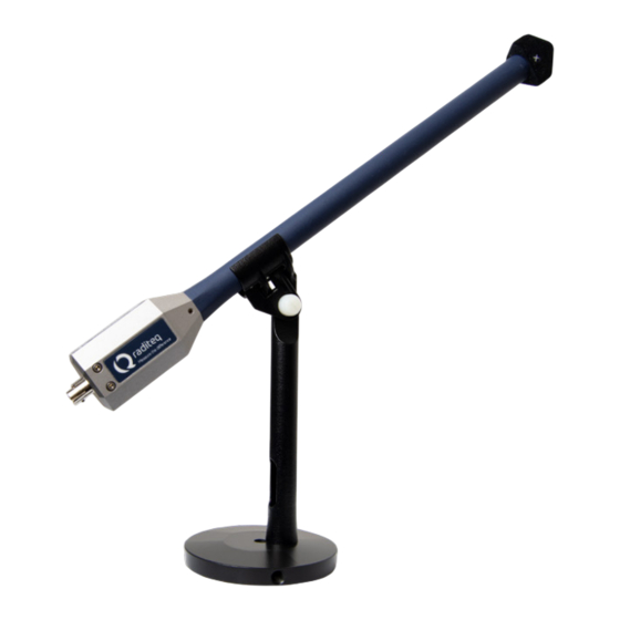
- Page 14 RadiSense® Stick probes are standard delivered with a small probe mast to position the RadiSense® at defined height and angle of 35.3 This product manual is subject to change without notice Page 14 of 34 Copyright © 2008 - 2024 Raditeq B.V.
- Page 15 FC connector - The natch for the FC connetor need be carefully locked into the slot befor it can be crewed on and tightened. ST Connector FC Connector This product manual is subject to change without notice Page 15 of 34 Copyright © 2008 - 2024 Raditeq B.V.
- Page 16 This product manual is subject to change without notice Page 16 of 34 Copyright © 2008 - 2024 Raditeq B.V.
- Page 17 Therefore when the probe is posistion ed as stated above the sticker should aline with the 3 axis and therefore the field orientations. This product manual is subject to change without notice Page 17 of 34 Copyright © 2008 - 2024 Raditeq B.V.
- Page 18 RadiSense® Product Manual RSS2018S | RSS2026S RSS2040S | RSS2060S Probe positioning illustration Note that this is applicable for all stick probe models. This product manual is subject to change without notice Page 18 of 34 Copyright © 2008 - 2024 Raditeq B.V.
- Page 19 RSS2040S | RSS2060S Installation of the plug-in card Please follow the instructions below on how to install the Raditeq plug-in card into the RadiCentre® correctly. NOTE: before installing and inserting a new plug-in card make sure that the RadiCentre® is turned OFF.
- Page 20 To meet the laser safety precaution, enter the laser code in the ‘LASER Code’ screen and press ‘OK’ for confirmation. The standard/default Laser code is 3447 This product manual is subject to change without notice Page 20 of 34 Copyright © 2008 - 2024 Raditeq B.V.
- Page 21 To control the RadiSense from a computer, one can use either custom made software or the RadiMation® EMC software package from Raditeq, which can be downloaded from the Raditeq website. If the RadiSense® is operated manually, this chapter can be skipped.
- Page 22 When the correct slot number is chosen, continue to set the communication of the RadiSense® by clicking ‘Communication tab’ (next page). This product manual is subject to change without notice Page 22 of 34 Copyright © 2008 - 2024 Raditeq B.V.
- Page 23 • • VISA When these steps are performed continue to the next steps for checking the communication of the RadiSense®. This product manual is subject to change without notice Page 23 of 34 Copyright © 2008 - 2024 Raditeq B.V.
- Page 24 It is also advised to visit the RadiMation® Wiki page and the FAQ section, which can be found at: https://wiki.radimation.com RadiMation® software can be downloaded at: https://www.raditeq.com/emc-test-software/radimation-download This product manual is subject to change without notice Page 24 of 34 Copyright © 2008 - 2024 Raditeq B.V.
- Page 25 5 * Notet that this is only applicable fo the RadiCentre® and RadiCentre® pro ( 2- and 7 Slots versions) This product manual is subject to change without notice Page 25 of 34 Copyright © 2008 - 2024 Raditeq B.V.
- Page 26 5 = 64 times average 11 = 4096 times averaging 6 = 128 times average 12 = 8192 times averaging This product manual is subject to change without notice Page 26 of 34 Copyright © 2008 - 2024 Raditeq B.V.
- Page 27 + Ez User correction data Every new RadiSense® probe is factory adjusted and verified at Raditeq. All required correction data (among linearity data for each axis) is stored inside the field probe. Additionally, “user correction factors” (for example ISO/IEC 17025 calibration correction values) can be stored into the RadiSense®...
- Page 28 The RadiSense® 18, 26 and 40 probe can store up to 200 “user correction factor” points. For manual uploading of the user correction data please refer to the white paper available on www.raditeq.com This product manual is subject to change without notice Page 28 of 34 Copyright © 2008 - 2024 Raditeq B.V.
- Page 29 After selecting the new correction file the following screen shall be presented. To add the required X, Y and Z correction column press the ‘Columns/Units’ button shown on this screen. This product manual is subject to change without notice Page 29 of 34 Copyright © 2008 - 2024 Raditeq B.V.
- Page 30 After filling in this data into the correction file, this could for example look like the following (typical RadiSense® 10 frequency response correction data). This product manual is subject to change without notice Page 30 of 34 Copyright © 2008 - 2024 Raditeq B.V.
- Page 31 This will enable the usage of the user calibration table during initialisation of the RadiSense® 10 when starting a test. This product manual is subject to change without notice Page 31 of 34 Copyright © 2008 - 2024 Raditeq B.V.
- Page 32 Warranty Conditions Raditeq B.V. offers a standard warranty term of three (3) years on their products, calculated from the shipping date, under the condition that the product is registered on www.raditeq.com. For registration of the product, the customer should provide the product model, serial number and the responsible reseller (if applicable).
- Page 33 Date of issue: Publish Date: 14/11/2024 Place of issue: Woerden, The Netherlands Authorized by: P.W.J. Dijkstra Title of authority: Director This product manual is subject to change without notice Page 33 of 34 Copyright © 2008 - 2024 Raditeq B.V.
- Page 34 Raditeq B.V. | Vijzelmolenlaan 3 | 3447GX Woerden | The Netherlands Raditeq B.V. | Vijzelmolenlaan 3 | 3447GX Woerden | The Netherlands www.raditeq.com | T:+31 348 200 100 www.raditeq.com | T:+31 348 200 100...
Need help?
Do you have a question about the PRO RadiSense RSS2018S and is the answer not in the manual?
Questions and answers