Table of Contents
Advertisement
Quick Links
Advertisement
Table of Contents

Related Manuals for Hyundai 20EPR-X


Summary of Contents for Hyundai 20EPR-X
- Page 1 20EPR-X, 25EPR-X Electric Pallet Truck Service Manual WARNING Do not use the pallet truck before reading and understanding this manual. NOTE: • Please check the designation of your present type at the last page of this document as well as on the ID-plate.
- Page 2 FOREWORD Before operating the truck, read this ORIGINAL INSTRUCTION HANDBOOK carefully and understand the usage of the truck completely. Improper operation could create danger. This handbook describes the usage of different electric pallet trucks. When operating and servicing the truck, make sure, that it applies to your type.
-
Page 3: Table Of Contents
TABLE OF CONTENTS 1. CORRECT APPLICATION ........................2. DESCRIPTION OF THE PALLET TRUCK .................... a. Overview of the main components ....................... b. Main technical data ..........................c. Description of the safety devices and warning labels (Europe and other, excepting USA) ....d. - Page 4 1) Standard torque......................... 2). Standard torque for fastening fittings..................12.TROUBLESHOOTING......................... 13.CURTIS HANDLE CONSOLE........................a. Power the console........................... b. Menu structure..........................c. Fault diagnosis menu........................d. Programming edit menu........................e. Parameter Settings..........................
-
Page 5: Correct Application
1. CORRECT APPLICATION It is only allowed to use this electric pallet truck according to this service manual. The trucks described in this manual are self-propelled electric power pallet trucks, with electrically powered low height lifting function as well for trucks with mast-lift and initial lift. The trucks are designed to lift, lower and transport palletized loads. -
Page 6: Description Of The Pallet Truck
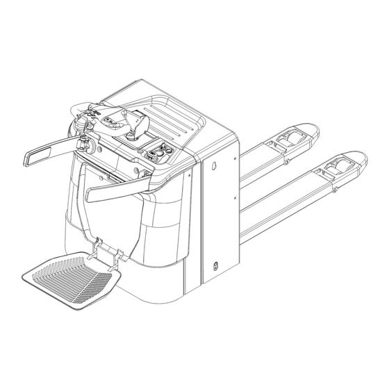
2. DESCRIPTION OF THE PALLENT TRUCK Overview of the main components Fig.1: Overview main components Safety (belly) button 11. Battery level indicator Tiller 12. USB port Top cover 13. Load roller Pin-code panel 14. Main cover Middle cover 15. Frame Protective arm cover 16. -
Page 7: Main Technical Data
Main technical data Fig. 2: Technical data... - Page 8 Table1: Main technical data for standard version Type sheet for industrial truck acc. to VDI 2198 Manufacturer`s type designation 20EPR-X 25EPR-X Power(battery,diesel,petrol gas,manual) Electric Operator type Pedestrian/ Stand Q (t) Load Capacity / rated load c (mm) Load center distance...
-
Page 9: Description Of The Safety Devices And Warning Labels (Europe And Other, Excepting Usa)
Description of the safety devices and warning labels Instruction label Warning label Load label Hock Identification plate Oil point injection label Indication label Warning information The truck is equipped with an emergency switch (9) which stops all lifting-, lowering-, driving- functions and engages the failsafe electromagnetic brake when it is pushed. - Page 10 Sign read and follow this instruction (A) Sign oil filling point (F) Indicating sticker (G) Warning sticker (B) Sign warning stay clear stop truck (H) Capacity sticker (C) Crane hook label (D)
-
Page 11: Identification Plate
Identification plate 1 Designation, type 7 Battery weight minimum/ maximum 2 Serial number 8 Nominal power in kW 3 Rated capacities in kg 9 Load center distance 4 Supply voltage in V 10 Manufacturing date 5 Own mass (self weight) in kg without battery 11 Option 6 Name and address of manufacturer) Fig. -
Page 12: Warnings, Residual Risk And Safety Instructions
3. WARNINGS, RESIDUAL RISK AND SAFETY INSTRUCTIONS DO NOT • Put foot or hand under or into the lifting mechanism. • Allow other person than the operator to stand in front of or behind the truck when it is moving or lifting/lowering. -
Page 13: Commissioning, Transporting, Decommissioning
• 4. COMMISSIONING, TRANSPORTING, DECOMMISSIONING Commissioning Commissioning data Table2: Type 20EPR-X 25EPR-X Hauled weight [kg] 670 kg 800 kg Dimensions [mm] 1865x730x1390 1950x730x1390 After receiving our new pallet truck or for re-commissioning you have to do the following before (firstly) operating the truck: •... -
Page 14: Decommissioning
d. Decommissioning For storage, remove the load, lower the truck to the lowest position, grease all greasing points mentioned in this handbook (regular inspection), eventually protect the truck against corrosion and dust. Remove the batteries and jack the truck safely to make sure no flattening after storage. For final decommissioning hand the truck to a designated recycling company. -
Page 15: Daily Inspection
5.DAILY INSPECTION This chapter describes pre-shift checks before putting the truck into operation. Daily inspection is effective to find the malfunction or fault on this truck. Check the truck on the following points before operation. Remove load from truck and lower the forks. DO NOT USE THE TRUCK IF ANY MALFUNCTION. -
Page 16: Operating Instructions
6.OPERATING INSTRUCTIONS BEFORE OPERATION, PLEASE FOLLOW THE WARNINGS AND SAFETY INSTRUCTIONS (CHAPTER 3). Make sure the load is palletized and stable, and the daily inspection is necessary. Insert the key switch (10), and start Press the horn button (21) to activate the audible warning signal. Fig7. -
Page 17: Steering
Start the truck by turning on the key switch (10), or activate by Pin-code panel, move the tiller to the operating area (‘F’, fig.9). Turn the acceleration button to the desired direction forward ‘Fw.’ or backwards Bw.’ (fig. 9). Fig 9: Operating direction Control the travelling speed by moving the acceleration button (20) carefully to reach the desired speed. -
Page 18: Braking
Braking THE BRAKING PERFORMANCE DEPENDS ON THE ROAD CONDITONS AND THE LOAD CONDITONS OF THE TRUCK The braking function can be activated by several ways below: • By moving the acceleration button (20) to the initial position ‘0’ or by releasing the button, the regenerative braking is activated. -
Page 19: Pin-Code Pane
7.PIN-CODE PANEL The truck can be equipped optional with a pin-code panel (4), start button (26) will replace the key switch (10) if equipped with pin-code panel. Fig.10: Pin-code panel a. Introduction Pin-code panel is an electronic system which is similar to an electronic alarm system. Truck will not available before entering a correct password, the main function is to prevent unauthorized operation. -
Page 20: A.controller Appearance
8.CONTROLLER AND ASSOCIATED EQUIPMENT a. Controller appearance Materials main controller relay copper bar fuse block M8 copper bar contactor fuse 150A copper bar fuse SYY fuse 80A copper bar steering controller fuse block fuse 10A... -
Page 21: B.controller Pin Definition
b. Controller pin definition Curtis F2-A LED state instruction light Connector pin diagram Curtis 1220E Connector pin diagram Definition Definition Definition Definition... - Page 22 c. Wiring/Circuit diagrams fuse 1: 10A fuse 2: 1.5A fuse 3: 0.5A fuse 01: 150A fuse 02: 80A fuse 03: 30A Fig. 11: circuit diagram Curtis F2-A+EPS1220E(Electric steering)EN1175 standard...
- Page 23 Fig 3: symbol description Code Name Code Name tiller steering motor capacity pulling motor steering controller proximity switch traction controller button switch FU01 fuse150A interlock switch1 FU02 fuse 80A interlock switch2 FU03 fuse 30A interlock switch3 fuse 10A interlock switch4 fuse tube1.5A proximity switch fuse 0.5A...
- Page 24 d.Testing and trouble clearing Current fault codes can be viewed in the dashboard and handheld programmer Testing A. controller Measure the diode voltage of the AC MOSFET circuit inside the controller (e.g. ZAPI), check for burn damage. Testing according to the table as below, each test item must be tested repeatedly more than 3 times. Multimeter terminal Range of normal value Item...
- Page 25 Note: The multimeter pointer cannot be reversely connected...
- Page 26 B. Line contactor and fuses For the line contactor fuses, connect an Ohm meter at the point shown in the figure, and check if the specified value measured.
-
Page 27: Replacement
For standard battery, the truck is equipped with the following lead-acid battery models: 20EPR-X 1 pc 2 PzS 24V/ 210 Ah (C5) [624 x 212 x 627 (LxWxH)] weight 185kg 25EPR-X 1 pc 3 PzS 24V/ 350 Ah (C5) [624 x 284 x 627 (LxWxH)] weight 288kg LEAD-ACID BATTERIES AND LITHIUM BATTERIES ARE ALLOWED. -
Page 28: Battery Indicator
c. Battery indicator Battery discharged Battery charged Fig. 14: Battery discharge indicator Hour meter An alpha-numeric liquid crystal display is fitted in the center of the unit that shows the hours worked. The display is backlight (the backlight is normally lighted). Alarms The corresponding fault code will appear on the display if there is a truck malfunction. - Page 29 Battery indicator (20CE:EN1175) Fig.15: Battery discharge indicator Hour meter An alphanumeric liquid crystal display is mounted in the center of the unit to indicate the speed of the truck. Alarms The same display can also indicate the alarm status, show the fault code corresponding to the alarm type. Battery State of Charge The battery's state of charge indication is integrated in the LCD display;...
-
Page 30: Charging
Table 5: Charger specifications (lead-acid battery) model specification 20EPR-X 30A24V 25EPR-X 45A24V The external charger of lithium-ion battery Parking the truck in a safety area which is dedicated for charging with a specific Fig 18: Lithium-ion charging power resource. - Page 31 Manufacturer`s type Battery type Capacity specification designation 24 V battery 2PzS-160Ah 24V /SN25A 24 V battery 2PzS-210Ah 24V /SN30A 20EPR-X 24 V battery Li-Ion 100Ah 24V60A 24 V battery Li-Ion 150Ah 24V60A 24 V battery Li-Ion 200Ah 24V80A 24 V battery...
- Page 32 c. Operation Remove dust cover Fig19:Remove dust cover Fig20:Mate couplers 2. Mate couplers Insert the male coupler on the single point watering system into the female coupler on the end of the water supply. 3.Observe flow indicator As the cells fill, the red balls inside the flow indicator will spin. As the valves close, the balls will begin to spin slower until they come to a stop.
- Page 33 f. Description of the lithium-ion battery The lithium-ion battery is a battery with rechargeable cells, the battery is designed for industrial trucks and can withstand related vibrations during operation. The battery is equipped with special connections for charging and discharging operations. Do not try to install or connected improper connectors to the battery. The battery is equipped with BMS –...
- Page 34 lithium-ion battery Tag Item Illustration nameplate bar code and QRcode warning label Nameplate and warning label Item illustration item illustration Manufacturer's mark Manufacturer's address Code electrical hazard marker Battery specifications Rechargeable logo Rated voltage Vertical upward packing, transportation Rated Capacity No labeling Energy Guide to use...
- Page 35 Storage, maintenance and transportation 1.Storage For long time storing, please Charge the battery pack to 50% (charge for 1-2 hours after discharging),place in a dry、ventilated area, and charge for 1-2hours every 3 months. The battery pack and the charger should be stored in a clean、dry and ventilated places, avoid contacting with the corrosive substances, be away from fire and heat sources.
- Page 36 Notes for battery using: Read the manual carefully before using the battery. * Do not put the battery pack into the water or wet it. * Do not charge the battery pack under ignition source or extremely hot conditions. * DO not use or store the battery pack near the heat source (such as fire or heater). If the battery leaks or smells, remove it away from the fire immediately.
-
Page 37: Hydraulic System
10.HYDRAULIC SYSTEM a. General survey The hydraulic system is composed of working oil pump, lifting cylinder and pipeline components. The hydraulic oil is supplied by the oil pump that connected to the motor directly. The oil pumps the hydraulic oil to the oil cylinder. 1). -
Page 38: Hydraulic Schematic Diagram
The pressure of the safety valve adjusted before leaving the factory, adjust and dismantle it privately is not allowed. b. Hydraulic schematic diagram lift cylinder lowering valve pressure throttle valve Hydraulic power unit (motor and oil pump) oil tank Fig.24: 20EPR-X hydraulic circuit... - Page 39 lift cylinder lowering valve throttle valve pressure controlling valve hydraulic power unit oil tank Fig.25: 25EPR-X hydraulic circuit c. Troubleshooting Pump motor fault Reason Bad connection or fuse burning. Check the battery connection. Check the key fuse. Check if hydraulic pump motor is likely to cause fuse burning.
-
Page 40: Hydraulic Pump
Hydraulic pump Fault Reason Low oil level Pump noise thick oil ( high viscosity ) The pump inlet line is limited Wear parts in the pump dirty oil Air leaks into the inlet line Low oil level High oil temperature Oil channel limited too thin oil Air leakage in the system... -
Page 41: Regular Maintenance
11.REGULAR MAINTENANCE Only qualified and trained personnel are allowed to maintain the truck. Before maintaining, remove the load from the forks and lower the forks to the lowest position. If you need to lift the truck, using designated lashing or jacking equipment according to the chapter 4b, before ... - Page 42 Check the current contactor • Check the frame for leakage (insulation test) • Check the drive controller for its function and wear • Check the electrical system of the drive motor • brake system Check the brake performance, replace the brake disc or adjust the air gap if necessary •...
-
Page 43: B.lubricating Points
Lubricating points Lubricate the marked points according to the maintenance checklist. The required grease specification is: DIN 51825, standard grease. Load roller Bearing Gear box Hydraulic system Electric steering system Fig. 26: Lubricating point s Connection point c. Check and refill hydraulic oil It is recommended to use hydraulic oil in connection with average temperature Environment –5℃~ 25℃... - Page 44 e. Remove, and reinstall the protective panel. Do not use the vehicle if the protection is damaged or not installed properly. Take down he clip that protected the guard plate, and then remove the guard plate. Setup procedure is opposite. Ensure that the guard plate is fixed correctly and not damaged.
- Page 45 Check and test during the disassembly The cause of the failure may be found during the disassembly process. Therefore, it is very important to check the contact parts and the status of the friction surface carefully. During the disassembly, measure and record the gaps, deformation, projection, and other factors that may cause the failure.
- Page 46 Check during assembly Check and record the individual part number in each step of the assembly process. Reassemble the gasket Install the gasket and washer in the same position as before, and check if the clearance is correct Assemble and adjust linking If no adjustments is required, assemble them into the same length as before.
- Page 47 When inserting the oil seal, use the guide and fixture to avoid damaging the oil seal. After inserting the oil seal, check the inclination (tilt tolerance: 0.2 mm / 00 mm, diameter 0.008 inch / 3.937 inch). When applying the adhesive to the oil seal, ensure that no adhesive touches the lip surface. Remove residual adhesive on the rail and fixture before inserting to another seal.
-
Page 48: Standard Torque
g. Standard torque Standard torque for the bolts and nuts Take care to avoid mixed metric and British size fasteners. Mismatch or incorrect Fasters may cause damage or fault of the vehicle, or may cause personal injury. Exceptions to these torques are available Service Manual if required. - Page 49 Standard torque of the fittings Standard torque for the sealing fittings of O-ring surface...
- Page 51 Taper pipe threaded fittings...
- Page 52 h. Wheel replacement procedure 1). Drive wheel Lift the truck with help of hydraulic jack Unscrew five nuts holding the tire Remove the tire Assemble back with reversed order Torque for nuts 90Nm...
-
Page 53: Support Wheel
2). Rollers Remove pins pos. 4 Remove axles pos. 12 Remove rollers pos. 11 Assemble in the reversed order 3). Support wheel Remove nut pos. 21 Remove bolt pos. 11 Replace wheel pos. 16 and bearings pos. 15 Assemble in the reversed order Sleeve pos. -
Page 54: Troubleshooting
12.TROUBLE SHOOTING If the truck has malfunctions follow the instructions, mentioned in chapter 6. Fig8: Trouble shooting TROUBLE CAUSE REPAIR Load weight too high Lift only the max. capacity, mentioned on the ID-plate Battery discharged Charge the battery Lifting fuse faulty Check and eventually replace the fuse Load can’t be lifted Hydraulic oil level too low... - Page 55 13.CURTIS HANDHELD PROGRAMMER a. The 1313 HANDHELD PROGRAMMER INTRODUCTION The Curtis 1313 Handheld Programmer (1313 HHP) performs programming and troubleshooting tasks for Curtis programmable motor controllers, gauges, and control systems. The 1313 HHP connects to Curtis devices in one of two ways—specific to the device: Either directly via the device’s RS232 serial port, or through a Controller Area Network (CAN) connection which can have multiple devices on the CANbus.
- Page 56 NOTICE This document refers to generic Curtis products. The images used are principally of the F2-A motor controller which may not match other devices or applications compatible with this 1313 HHP. This manual does, however, describe the usage of the applications (app) that can be used for all compatible devices.
- Page 57 b.1313 HHP OPERATION This Chapter describes how to use the 1313 HHP for CAN-based communication devices. Although there are similarities between the CAN-based devices and the serial devices, there are differences in the connection and the apps. CONNECTIONS The 1313 HHP has two connectors, one for communicating with the devices and one for interfacing with a PC. The 1313 HHP also has a battery compartment and a memory card slot.
- Page 58 1313-xx31 Wiring D-Sub Pin Function CAN_H CAN_L B+ (8–36 V) B– Vehicle Harness Wiring for CAN Connected 1313 HHP POWER-ON THE 1313 HHP Connect the 1313 HHP to the system by plugging it into the system’s CANbus using the supplied DB9 CAN-port cable. If the CAN connection point provides power, the 1313 HHP will automatically power up.
-
Page 59: Display Format
DISPLAY FORMAT The high-resolution clarity of the LCD screen allows a wealth of information to be displayed at once. The example below shows the information available in the Main Screen. green circle ( ) indicating online mode Red slash ( ) indicating offline mode icon indicating access... - Page 60 Access levels: OEM Factory: OEM Dealer: Field Advanced: Field Intermediate: Field Basic: KEY FUNCTIONS The pushbutton keys on the 1313 HHP’s keypad allow rapid navigation through the apps. softkeys arrow keys ±keys Power help favorites Main screen...
- Page 61 Softkeys These three keys are blank because their function is context-specific. At any given time, their function is shown directly above them on the LCD screen. The symbol “»” indicates more options. Pressing the softkey under the “»” will scroll to another set of softkey options. Arrow Keys Use these four keys to scroll up-and-down and right-and-left within the display screen.
- Page 62 Screenshots Momentarily press the Power Key and then momentarily press the Favorites key to save the present image of the LCD display. These are called screenshots. Main Screen Pressing this key will return the 1313 HHP to the Main Screen from any location. When the main screen is displayed, use this key to cycle through the individual apps.
- Page 63 c. DEVICE Device Details and Connection To use the 1313 HHP, a device must be compatible and then a CAN connection established. The Device app is where devices (CAN nodes) discovered during the startup CANbus-scan are listed*. After the 1313 powers up and completes the start -up scan, the Main Screen is displayed with the Devices app highlighted.
- Page 64 (1) 1313 HHP startup-scan of CANbus for devices (2) Main Screen following the CANbus scan Just the “Offline” capable apps are available. (3) “Select” softkey—opens app and lists devices (4) “Details” softkey—returns device information (5) “Connect” softkey—receiving data progress (6) Device connected—all apps are available...
- Page 65 d.PROGRAMMER The Programmer* app is where parameters, monitor variables, active-faults, and the fault -history are accessed. There are no separate monitor and diagnostics apps on the main screen. This chapter covers all of the items that can be accessed with the Programmer. It is recommended that the Device manual be consulted for explanations of the read/write and read only variables viewable within Programmer.
- Page 66 PROGRAMMER STRUCTURE When any of the app’s top-level menus are selected ( ) the name of the app is displayed adjacent to the Programmer icon. When navigating through a hierarchical menu, the text at the top of the screen expands to show the path taken.
- Page 67 ADJUSTING/EDITING PARAMETERS Within Programmer, use the down ( ) or up ( ) arrows to navigate between parameters, monitor-items, or sub-menus. If the menu contains more than the 8 items shown on the screen, a scrollbar appears at the right edge of the screen. When a scrollbar is present, the lines wrap around so that navigating up from the top line/item navigates the screen to the last line/item on the list and vice versa.
- Page 68 14. Controller Fault Code Table Countermeasures of fault codes for Curtis AC-F2-A controller Fault Fault Name Solution code 1.The external U, V or W connection of the motor is short-circuited; 2. Motor parameters do not match; Controller Overcurrent 3. Controller failure; 4.
- Page 69 1. The working environment of Controller is harsh; 2. Vehicle overload; Controller Overtemp 3. The controller is not installed correctly; Cutback Set: radiator temperature exceeds 85℃ Clear: reduce the temperature 1. The battery is low 2. Battery parameter setting error 3.
- Page 70 1. Open circuit or short circuit of connected load Coil3 Driver Open/Short 2. The connecting pin is dirty 3. Wrong wiring 1. Open circuit or short circuit of connected load Coil4 Driver Open/Short 2. The connecting pin is dirty 3. Wrong wiring 1.
- Page 71 constant USER 1 FAULT PDO Fault Rema constant USER 2 FAULT PDO Timeout BMS constant USER 3 FAULT User HPD Fault constant USER 4 FAULT Throttle Open Fault constant USER 5 FAULT Interlock SRO constant USER 6 FAULT GPS Flag Lock 1 constant USER 9 FAULT GPS No Communication Fault constant USER 10 FAULT...
- Page 72 constant USER 22 FAULT Throttle ON Without Interlock Fault 5-15 6-10 constant USER 23 FAULT BMS Cell Undervolt Fault constant USER 24 FAULT BMS Temp Fault 6-11 6-12 constant USER 25 FAULT BMS Cell voltage Fault 6-13 constant USER 26 FAULT BMS LOW AH 6-14 constant USER 27 FAULT...
- Page 73 Motor Type Fault Motor type parameter value is out of range VCL/OS Mismatch VCL program in Controller does not match OS program 1. The vehicle still moves after the electromagnetic brake EM Brake Failed to Set command is set. 2. The braking force of electromagnetic brake is too small 1.
- Page 74 EPS 1220E Fault Code STEER TRACTION FLASH CLEAR NAME POSSIBLE CAUSE FAULT FAULT CODE CONDITION ACTION ACTION Controller 1. The steer motor wires shorted. Cycle KSI Shutdown 1 = Stop Overcurrent 2. Controller defective. Current 1. Controller defective. Cycle KSI Shutdown 1 = Stop Sense Fault...
- Page 75 Motor Short 1. The steer motor wires shorted. Cycle KSI Shutdown 1 = Stop Encoder 1. Encoder is broken. Cycle KSI Hold then 1 = Stop Fault 2. Encoder wiring is open. Shutdown 3. Controller defective. Fault Output 1. Incorrect Fault Output wiring. Cycle KSI Shutdown 1 = Stop...
- Page 76 2. Parameters are restored to the default settings. Interlock 1. A fault is set if the 2 switch inputs are Cycle KSI Interlock = 1 = Stop Switch not matched. Supervision 2. Interlock switch defective. Home Switch 1. When the wheel position is not close to Cycle KSI Warning 1 = Stop...
- Page 77 1. Calibration data is out of range Cycle KSI Shutdown 1 = Stop Calibrations Parameter 1. Parameter data out of range Cycle KSI Shutdown 1 = Stop Out of Range Supervision 1. Supervisor defective Cycle KSI Shutdown 1 = Stop...
Need help?
Do you have a question about the 20EPR-X and is the answer not in the manual?
Questions and answers