Table of Contents
Advertisement
Quick Links
Advertisement
Table of Contents
Troubleshooting

Related Manuals for Hyundai 25EP-X


Summary of Contents for Hyundai 25EP-X
- Page 1 16/20/25EP-X Pallet Truck Service Manual WARNING Do not use the pallet truck before reading and understanding these operating instructions. NOTE: • Please check the designation of your present type at the last page of this document as well as on the ID-plate.
- Page 2 FOREWORD Before operating the truck, read this ORIGINAL INSTRUCTION HANDBOOK carefully and understand the usage of the truck completely. Improper operation could create danger. This handbook describes the usage of different electric pallet trucks. When operating and servicing the truck, make sure, that it applies to your type.
-
Page 3: Table Of Contents
Contents CORRECT APPLICATION ......................10 DESCRIPTION OF THE PALLET TRUCK .................. 11 Overview of the main components ....................11 Main technical data ........................12 Description of the safety devices and warning labels ..............14 Identification plate ........................15 WARNINGS, RESIDUAL RISK AND SAFETY INSTRUCTIONS ..........16 COMMISSIONING, TRANSPORTING, DECOMMISSIONING ............ - Page 4 11. REGULAR MAINTENANCE ......................52 Maintenance checklist ......................... 52 Lubricating points ........................54 Check and refill hydraulic oil ......................55 Checking electrical fuses ......................55 12. TROUBLESHOOTING ........................ 57 13. The CURTIS control system ......................57 The Curtis handheld programmer ....................58 1313 HHP OPERATION ......................
-
Page 5: Correct Application
1. CORRECT APPLICATION It is only allowed to use this electric pallet truck according to this instruction handbook. The trucks described in this handbook are self-propelled electric power pallet trucks, with electrically powered low height lifting function as well for trucks with mast-lift and initial lift. The trucks are designed to lift, lower and transport palletized loads. -
Page 6: Description Of The Pallet Truck
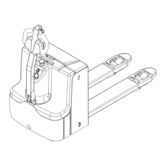
2. DESCRIPTION OF THE PALLET TRUCK Overview of the main components Fig. 1: Overview main components Electrical box cover Key switch Battery discharge Indicator Fork chassis Tiller 10. Load wheels Accelerator 11. Drive wheel Safety (belly) button 12. Castors Instrument board cover 13. -
Page 7: Main Technical Data
Main technical data Fig. 2: Technical data 16/2EP-X Fig. 3: Technical data 25EP-X... - Page 8 Table 1: Main technical data for standard version Type sheet for industrial truck acc. to VDI 2198 Manufacturer`s type designation 16EP-X 20EP-X 25EP-X Power(battery,diesel,petrol gas,manual) Battery Operator type Pedestrian Load Capacity (upper and lower pallets) Q (t) Load center distance...
-
Page 9: Description Of The Safety Devices And Warning Labels
Follow also the instructions given on the decals. Replace the decals if they are damaged or missing. Fig. 5: Safety and warning labels 25EP-X... -
Page 10: Identification Plate
Identification plate Fig. 6: Identification plate The content of the nameplate layout is subject to the equipment posting. -
Page 11: Warnings, Residual Risk And Safety Instructions
3. WARNINGS, RESIDUAL RISK AND SAFETY INSTRUCTIONS DO NOT • Put foot or hand under or into the lifting mechanism. • Allow other person than the operator to stand in front of or behind the truck when it is moving or lifting/lowering. -
Page 12: Commissioning, Transporting, Decommissioning
4. COMMISSIONING, TRANSPORTING, DECOMMISSIONING Commissioning Table 2: Commissioning data Type 16EP-X 20EP-X 25EP-X Commissioning weight [kg] Dimensions [mm] 1385x729x1670 1385x729x1735 1950X729X1385 After receiving our new pallet truck or for re-commissioning you have to do following before (firstly) operating the truck: Check if are all parts included and not damaged •... -
Page 13: Daily Inspection
5. DAILY INSPECTION This chapter describes pre-shift checks before putting the truck into operation. Daily inspection is effective to find the malfunction or fault on this truck. Check the truck on the following points before operation. Remove load from truck and lower the forks. DO NOT USE THE TRUCK IF ANY MALFUNCTION IS FOUND. -
Page 14: Parking
Lifting DO NOT OVERLOAD THE TRUCK! THE MAXIMUM CAPACITY IS 1600kg (16EP-X) , 2000kg (20EP-X),2500kg (25EP-X) Travel with the lowered forks fully underneath the pallet until the load and press the lifting button (15) until you reached the desired lifting height. -
Page 15: Travelling
Travelling TRAVEL ON INCLINES ONLY WITH THE LOAD FACING UPHILL DO NOT TRAVEL ON INCLINES MORE THAN SPECIFIED WITH THE TECHNICAL DATA. Fig. 11: Operating direction Turn on the key switch (8) to start the vehicle and move the handle to the operation area 'F'. Turn the acceleration button in the desired direction forward 'Fw.' or backward 'Bw.' Carefully move the acceleration button (4) to control the driving speed until the desired speed is reached. -
Page 16: Steering
Steering Steering the truck by moving the tiller to the left or right side. Braking THE BRAKING PERFORMANCE DEPENDS ON THE TRACK CONDITONS AND TRHE LOAD CONDITONS OF THE TRUCK The braking function can be activated on several ways: • By moving the accelerator button (4) back to the initial ‘0’ position or by releasing the button, the regenerative braking is activated. -
Page 17: Malfunctions
Malfunctions If there are any malfunctions or the truck is inoperative, please stop using the truck and activate the emergency button (7) by pushing it. If possible, park the truck on a safe area and remove the key switch (8).Inform immediately the manager and, or call your service. If necessary, tow the truck out of the operating area by using dedicated towing/ lifting equipment. -
Page 18: Controllers And Related Devices
7. Controllers and related devices Controller appearance The AC-0 controller is used as an example. For other models, see the parts manual Item Description Plate Controller Copper Busbar Contactor Holder Copper Busbar Relay Copper Busbar Fuse 150A Copper Busbar Fuse Holder Fuse 80A Holder Fuse Holder... -
Page 19: Wiring/ Circuit Diagram
WIRING/ CIRCUIT DIAGRAM b-1 16/ 20/ 25EP-X (CURTIS System) FU01: 150A FU02: 80A FU1: 10A FU2: 0.5A Fig. 12: Electrical diagram... - Page 20 Table 3: Description of electrical diagram Code Item Code Item Battery Relay Emergency button Proximity switch Controller Indicator Main contactor Tiller FU01 Fuse 80A Capacitor FU02 Fuse 150A Horn Fuse 10A Micro switch Key switch Electromagnetic valve Lifting contactor Traction motor Steering Controller Electromagnetic brake Pump motor...
- Page 21 16/ 20/ 25EP-X Li (CURTIS System) FU01: 150A FU02: 80A FU1: 10A FU2: 0.5A FU3: 1.5A Fig. 13: Electrical diagram (16/20/25EP-X Li)
-
Page 22: Test And Troubleshoot
Table 4: Description of electrical diagram Code Item Code Item Li battery Relay Emergency button Proximity switch Controller Indicator Main contactor Tiller FU01 Fuse 80A Capacitor FU02 Fuse 150A Horn Fuse 10A Micro switch Key switch Electromagnetic valve Lifting contactor Traction motor Steering Controller Electromagnetic brake... - Page 23 Test Controller Measure the diode voltage of the AC MOSFET (ZAPI for example) circuit in the controller, and check whether it is burnt or damaged. Each test item must be tested repeatedly for more than 3 times. Multi-meter Normal range item terminals Red pen...
- Page 24 B. Wiring contactor and fuse measurement For line contactors and line fuses, connect an ohmmeter (multi-meter set to Ohm) at the point shown in the figure and check that it measures the specified value.
-
Page 25: Battery Charging And Replacement
67kg 624x212x627mm 24 V battery Li-Ion 200Ah 80kg 624x212x627mm 24 V battery 3PzS-350Ah 285kg 624x284x627mm 25EP-X 24 V battery Li-Ion 150Ah 83kg 624x284x627mm 24 V battery Li-Ion 200Ah 90kg 624x284x627mm LEAD-ACID BATTERIES AND LITHIUM BATTERIES ARE ALLOWED FOR APPLICATION. THE WEIGHT OF THE BATTERIES HAS AN INFLUENCE TO THE TRUCKS OPERATING BEHAVIOR. -
Page 26: Replacement
The installation is in the reverse order of the removal. Please connect the positive terminals firstly. Otherwise the tuck could be damaged. Note: for 20EP-X, if you would like to exchange to the side, please refer to 25EP-X. Fig. 17: Battery a-1 LIFTING TYPE 1. - Page 27 a-2 Side pull 1. Open the lid of the battery case 2. Unplug the power 3. Unscrew the retaining bolt by hand 4. Lift the crank and release the battery retainer 5. Take the battery out in the direction indicated by the arrow, and the installation process is the reverse process of disassembly.
-
Page 28: Maintenance Of Lead-Acid Batteries
Maintenance of lead-acid batteries 1. Cause of water supply of battery The battery recharge is due to the electrolytic effect of the battery at the later charging stage, which makes the moisture part of the electrolyte electrolyze. After a long period of charge and discharge, the water content of the battery will be more electrolytic, which will increase the electrolyte potency and decrease the liquid level. - Page 29 1. Unplug battery switch 2. Unscrew the battery water cap Battery bus-bar separator 3. Electrolyte lever is lower than bus-bar, then add 4. In some battery filling holes, the bus bar is not distill water visible. When the liquid level drops to 10mm away from the battery partition, water is added Maximum liquid level...
-
Page 30: Battery Indicator
Battery indicator The discharge situation is represented by 10 red LED display segments. Battery indicator(CURTIS) Normal Malfunction Fig. 19: Battery indicator The main interface displays as shown in the figure above. Hour meter The digital counter after Hourglass Symbol indicates the working hour of the truck. Unit:H Battery state of charge It displays the battery symbol and the current battery level. -
Page 31: Charging
24V /SN30A 24 V battery Li-Ion 100Ah 24V60A 20EP-X 24 V battery Li-Ion 150Ah 24V60A 24 V battery Li-Ion 200Ah 24V80A 24 V battery 3PzS-350Ah 24V /SN45A 25EP-X 24 V battery Li-Ion 150Ah 24V60A 24 V battery Li-Ion 200Ah 24V80A... -
Page 32: Battery Label
Description of the lithium-ion battery ● The lithium-ion battery is a battery with rechargeable cells ● The battery is designed for industrial trucks and can withstand related vibrations during operation. ● The battery is equipped with special connections for charging and discharging operations. ●... - Page 33 Nominal voltage of No putting into ordinary garbage bins Rated capacity of battery No long-term exposure to sunshine Battery energy of battery Stay away from fire Weight of battery Keep out of the rain Configuration of battery Guide to use Protocol version of Production date Production serial No.
-
Page 34: Safety Instructions, Warning Indications And Other Notes
Safety Instructions, Warning Indications and other Notes Safety regulations for handling lithium-ion batteries Do not try to make any repairs or servicing of lithium batteries Risk of electric shock and burning The battery’s charging and discharging connectors have open terminals, avoid any body contacts, contamination or direct contacts with objects which can cause short circuit connection of terminals. - Page 35 Potential hazards If equipment is used according to its design purpose, following the correct operations procedures, there are no hazards anticipated. The following hazards can arise in the event of improper use: • Physical damage to the battery in case a battery falls or is deformed through impacts. Mechanical damages can cause leakages of harmful materials, fire or battery explosion.
- Page 36 Protect the lithium-ion battery from solar radiation or other forms of heat radiation. Do not expose the lithium-ion battery to heat sources. Keep out of the rain. Explosion and fire hazard Physical damage, thermal effects or incorrect storage in the event of a defect can result in explosions or fire. The battery materials can be flammable.
- Page 37 This type of damage may be caused by a short circuit inside the battery, which may result in leakage of harmful materials, fire or battery explosion. Material discharge Battery electrolyte fluid can be hazardous Electrolyte fluid can be discharged if the battery is physically damaged. Avoid its contact with skin or eyes. If the contact happened: Rinse the affected parts with big amount of water and request for medical assistance immediately.
- Page 38 Storage of batteries Deep Discharge can damage the battery If the battery is not used for a long period of time, it can become damaged through discharge. ● Before a long period of inactivity, the battery must be charged to the level of at least 70%. ●...
-
Page 39: Drive/Brake System
9. Drive/brake system a. Overview The drive/brake system includes the following: 1) The drive motor controlled by the controller transmits the rotating power to the drive shaft (electric-mechanical power) 2) The drive shaft converts the rotational power transmitted from the drive motor through its gear set into the torque and speed suitable for the drive, and sends it to the corresponding wheels (mechanical power). - Page 40 Remove and install the drive assembly Preliminary steps 1 Park the vehicle safely and remove the drive wheel cover 2 Turn off the emergency stop switch and key switch 3 Disconnect the battery connector Disassembly procedure 1) Remove the drive motor cover and handle seat, and then remove 8 screws, 2) Unplug the harness connector of the motor 3) Remove the screw and take off the motor power cord connector...
-
Page 41: Brakes
4) Remove and replace the 5 screws fixing the PU ring with a 17mm wrench 5) The reverse process of installation and disassembly b. Brakes Appearance Brake removal and installation Remove the brake by removing the three screws that are fixed to the drive wheel with a 5mm hex wrench. -
Page 42: Hydraulic System
Hydraulic system Overview The hydraulic system is composed of working oil pump, lifting oil cylinder, pipeline and other parts. The hydraulic oil is supplied by the oil pump directly connected with the motor. The oil pump sends the hydraulic oil to the cylinder. - Page 43 2) Detection The pump motor transmits the power to the main hydraulic pump electrically to pump hydraulic oil to operate the hydraulic system The pump motor is connected to the controller through the motor contactor. The controller operates the pump motor contactor according to the input from multiple switches and sensors and the internal parameter settings The pump motor operates when the following conditions are met: The key emergency stop switch is closed...
-
Page 44: Hydraulic Circuit
Hydraulic circuit Lift cylinder Lowering valve Pressure valve Throttle valve Hydraulic power pack (motor and pump) Oil tank Fig. 22: 16/20EP-X Hydraulic circuit Lift cylinder Lowering valve Throttle valve Pressure valve Hydraulic power pack Oil tank Fig. 26: 25E-X Hydraulic circuit... -
Page 45: Troubleshooting
TROUBLESHOOTING Pump Motor Trouble Possible cause Poor connection or blown fuse. Check the battery connection. Check the key fuse. Check whether the fuse of the hydraulic pump motor may be blown. Key switch, upper limit switch and line contactor are not closed. - Page 46 The pump is too worn. The system operates under too high pressure. The shaft seal is worn out. Leakage at pump shaft seal. The pump body is worn internally. Operation with low oil level in the tank will cause the seal to be sucked.
-
Page 47: Regular Maintenance
REGULAR MAINTENANCE Only qualified and trained personnel are allowed to do maintenance on this truck. • Before maintaining, remove the load from the forks and lower the forks to the lowest • position. • If you need to lift the truck, follow chapter 4b by using designated lashing or jacking equipment. - Page 48 17 Test the Emergency switch function • 18 Check the electric drive motor for noise and damages • 19 Test the display • 20 Check, if correct fuses are used • 21 Test the warning signal • 22 Check the contactor(s) •...
-
Page 49: Lubricating Points
Lubricating points Lubricate the marked points according to the maintenance checklist. The required grease specification is: DIN 51825, standard grease. Fig. 24: Lubricating point s Steering castor bearing Support castor bearing Pump Axle Joint Load roller bearing... -
Page 50: Check And Refill Hydraulic Oil
• • Depending on the type the amount is 0,7L(16/2EP-X) and 0.8L(25EP-X) Waste material like oil, used batteries or other must be probably disposed and recycled according to the national regulations and if necessary brought to a recycling company. The oil level height shall be in the not lifted position min.0.6L to 0.8L. - Page 51 Fig. 26: Location fuses(16/ 20/ 25EP-X) (CURTIS) Table 9: Size fuses(16/ 20/ 25EP-X) Rate 0.5 A 10 A FU01 FU02 150A...
-
Page 52: Troubleshooting
TROUBLESHOOTING • If the truck has malfunctions follow the instructions, mentioned under chapter 6. Table 10: Trouble shooting TROUBLE CAUSE REPAIR Load weight too high Lift only the max. capacity, mentioned on the ID-plate Battery discharged Charge the battery Lifting fuse faulty Check and eventually replace Load can’t be lifted the lifting fuse... -
Page 53: The Curtis Control System
The CURTIS control system a. The Curtis handheld programmer INTRODUCTION The Curtis 1313 Handheld Programmer (1313 HHP) performs programming and troubleshooting tasks for Curtis programmable motor controllers, gauges, and control systems. The 1313 HHP connects to Curtis devices in one of two ways—specific to the device: Either directly via the device’s RS232 serial port, or through a Controller Area Network (CAN) connection which can have multiple devices on the CANbus. - Page 54 This manual, RevC July 2022, is updated for the following 1313 HHP software. Consult the Application Note: 1313 HHP Software Update, RevG (pdf) for the software matching the revisions shown. Update to both the Serial and CAN (this manual) software versions as illustrated below.
- Page 55 Controller (Vehicle System) Connector 1313-xx31 Wiring D-Sub Pin Function CAN_H CAN_L B+ (8–36 V) B– Vehicle Harness Wiring for CAN Connected 1313 HHP...
-
Page 56: 1313 Hhp Operation
POWER-ON THE 1313 HHP Connect the 1313 HHP to the system by plugging it into the system’s CANbus using the supplied DB9 CAN-port cable. If the CAN connection point provides power, the 1313 HHP will automatically power up. If not, press the power key ( ) and it will power up and run off its internal batteries (if batteries are installed). - Page 57 DISPLAY FORMAT The high-resolution clarity of the LCD screen allows a wealth of information to be displayed at once. The example below shows the information available in the Main Screen. green circle ( ) indicating online mode Red slash ( ) indicating offline mode icon indicating access...
- Page 58 Access levels: OEM Factory: OEM Dealer: Field Advanced: Field Intermediate: Field Basic: KEY FUNCTIONS The pushbutton keys on the 1313 HHP’s keypad allow rapid navigation through the apps. softkeys arrow keys ±keys Power help Main screen favorites...
- Page 59 Softkeys These three keys are blank because their function is context-specific. At any given time, their function is shown directly above them on the LCD screen. The symbol “»” indicates more options. Pressing the softkey under the “»” will scroll to another set of softkey options. Arrow Keys Use these four keys to scroll up-and-down and right-and-left within the display screen.
- Page 60 Screenshots Momentarily press the Power Key and then momentarily press the Favorites key to save the present image of the LCD display. These are called screenshots. Main Screen Pressing this key will return the 1313 HHP to the Main Screen from any location. When the main screen is displayed, use this key to cycle through the individual apps.
-
Page 61: Device
c. DEVICE Device Details and Connection To use the 1313 HHP, a device must be compatible and then a CAN connection established. The Device app is where devices (CAN nodes) discovered during the startup CANbus-scan are listed*. After the 1313 powers up and completes the start -up scan, the Main Screen is displayed with the Devices app highlighted. - Page 62 (1) 1313 HHP startup-scan of CANbus for devices (2) Main Screen following the CANbus scan Just the “Offline” capable apps are available. (3) “Select” softkey—opens app and lists devices (4) “Details” softkey—returns device information (5) “Connect” softkey—receiving data progress (6) Device connected—all apps are available...
-
Page 63: Programmer
d. PROGRAMMER The Programmer* app is where parameters, monitor variables, active-faults, and the fault -history are accessed. There are no separate monitor and diagnostics apps on the main screen. This chapter covers all of the items that can be accessed with the Programmer. It is recommended that the Device manual be consulted for explanations of the read/write and read only variables viewable within Programmer. - Page 64 PROGRAMMER STRUCTURE When any of the app’s top-level menus are selected ( ) the name of the app is displayed adjacent to the Programmer icon. When navigating through a hierarchical menu, the text at the top of the screen expands to show the path taken.
- Page 65 ADJUSTING/EDITING PARAMETERS Within Programmer, use the down ( ) or up ( ) arrows to navigate between parameters, monitor-items, or sub-menus. If the menu contains more than the 8 items shown on the screen, a scrollbar appears at the right edge of the screen. When a scrollbar is present, the lines wrap around so that navigating up from the top line/item navigates the screen to the last line/item on the list and vice versa.
-
Page 66: Trouble Shooting For Curtis System (Curtis-F2-A)
e. Trouble shooting for Curtis system (Curtis-F2-A) Fault Fault Name Solution Fault Note Code Source AC-F2-A 1. The external U, V or W connection of the motor Controller is short-circuited; 2. Motor parameters do not match; Controller Overcurrent 3. Controller failure; 4. - Page 67 AC-F2-A 1. Controller works under restricted conditions; Controller 2. The working environment of the controller is Controller Undertemp harsh; Cutback Set: radiator temperature is lower than - 25 ℃ Clear: make the radiator temperature higher than - 25 ℃ AC-F2-A 1.
- Page 68 AC-F2-A 1. Open circuit or short circuit of connected load Coil 1 Driver Controller 2. The connecting pin is dirty Open/Short 3. Wrong wiring AC-F2-A 1. Open circuit or short circuit of connected load Controller Main Open/Short 2. The connecting pin is dirty 3.
- Page 69 AC-F2-A Writing to EEPROM memory failed. This may be Controller caused by the VCL writing to the EEPROM, or the EEPROM Failure CAN BUS, or the wrong parameters programmed into the Controller after the programmer parameters are adjusted. AC-F2-A 1. Key start, interlock, direction, and Throttle input Controller sequence settings are wrong HPD/Sequencing Fault...
- Page 70 constant USER 1220 Limit Fault AC-F2-A OEM Faults FAULT Controller 5-10 constant USER Handshake Fault AC-F2-A OEM Faults FAULT Controller 5-11 constant USER BMS Fault Grade Non Zero AC-F2-A OEM Faults FAULT Controller 5-12 constant USER PDO Fault ECS AC-F2-A OEM Faults FAULT Controller...
- Page 71 AC-F2-A 1. Motor locked Controller 2. Motor encoder failure Stall Detected 3. Wrong wiring 4. Input motor encoder power failure AC-F2-A Code comparison occurs during motor matching: Controller 0=normal 1=The controller receives the encoder number, but the pulse quantity is not defined. Please set the pulse value manually 2=motor temperature sensor failure Motor Characterization...
Need help?
Do you have a question about the 25EP-X and is the answer not in the manual?
Questions and answers