Table of Contents
Advertisement
Quick Links
Advertisement
Table of Contents
Troubleshooting

Related Manuals for Datalogic SC5100


Summary of Contents for Datalogic SC5100
- Page 1 SC5100 PRODUCT REFERENCE GUIDE Controller...
- Page 2 Electronic versions of this document may be downloaded from the Datalogic website (www.datalogic.com). If you visit our website and would like to make comments or suggestions about this or other Datalogic pub- lications, please let us know via the "Contact" page.
-
Page 3: Table Of Contents
System Event LEDs ..........................5 Ethernet Status LEDs ..........................5 Keypad and Display ......................5 Menu Functions and Navigation ......................6 Checking The Scanners are Reading with SC5100 Display ..........14 SC5100 Versions ..........................15 Accessories ............................15 Guide to Installation ....................... 18 CHAPTER 2. MECHANICAL INSTALLATION.............. 19 Preparing for Mechanical Installation ................ - Page 4 Enter REDS Settings on SC5100 Keypads ..................69 Power Off System ..........................70 Connect ALL Devices ........................70 Power-up System ..........................70 Check Status of PRIMARY and BACKUP SC5100 .............. 71 Setting up redundant Operation ..................72 Bidirectional Setup ......................75 SC5100 CONTROLLER...
- Page 5 CONTENTS CHAPTER 6. MAINTENANCE ................... 78 Backup and Automatic Replacement Procedure ............... 78 Backing Up the System Using e-Genius ...................78 Replacing an SC5100 .........................78 CHAPTER 7. TROUBLESHOOTING................80 Troubleshooting GuidES ....................81 Online Mode - NO READ ......................81 PackTrack Mode - NO READ ....................82 Online Mode - NO READ MESSAGE ..................83...
- Page 6 Ethernet TCP/IP to Host ......................124 COM to Host ..........................125 Fieldbus to Host ........................125 EBC - Syncnet Mixed Layout ......................126 Redundant System Layout ......................127 Redundant System Layout with Host supporting Serial COM Communications ....128 Technical Specifications ....................129 SC5100 CONTROLLER...
-
Page 7: Preface
ESD: This symbol identifies a procedure that requires you take measures to prevent Electrostatic Discharge (ESD) e.g., use an ESD wrist strap. Circuit boards are most at risk. Please follow ESD procedures. SC5100 CONTROLLER... -
Page 8: Technical Support
Products once sold. The Warranty Period shall be two years from the date of shipment by Datalogic, unless otherwise agreed in an applicable writing by Datalogic. Datalogic will not be liable under the warranty if the Product has been exposed or subjected to any: (1) maintenance, repair, installation, handling, packaging, transportation, storage, operation or use that is improper or otherwise not in compliance with Datalogic’s instruction;... -
Page 9: Sc5100 End User License Agreement
Products; (iv) rent or transfer all or some of the Software to any other party without Datalogic’s prior written consent. 1.3. Title to the licensed Software shall be and remain with Datalogic or the third party from whom Datalogic has obtained a license right. This Agreement does not grant to End User any intellectual property rights. - Page 10 (additional) license fees due and any further damages, if any. 2. License Fee License fees shall be due by End User to Datalogic according to the terms provided for in the relevant contract for the purchase of the Datalogic Product.
- Page 11 Technical Data and Computer Software clause at DFARS 252.227-7013(c)(1)(ii), which- ever is applicable. 8.2 If End User is using the Datalogic Product outside of the United States, End User must comply with the applicable local laws of the country in which the Datalogic Prod- uct is used and with U.S.
- Page 12 Notices to Datalogic shall be sent to the attention of Datalogic IP Tech S.r.l., Legal & IP Department, Via San Vitalino 13, 40012 Calderara di Reno (Bologna), Italy, or such other address as may be specified by Datalogic in writing.
-
Page 13: Compliance
Datalogic commercial reference contacts. Since April 20th, 2016 the main European directives applicable to Datalogic products require inclusion of an adequate analysis and assess- ment of the risk(s). This evaluation was carried out in relation to the applicable points of the standards listed in the Declaration of Conformity. -
Page 14: Eac Compliance
FCC Compliance Modifications or changes to this equipment without the expressed written approval of Datalogic could void the authority to use the equipment. This device complies with PART 15 of the FCC Rules. Operation is subject to the follow- ing two conditions: (1) This device may not cause harmful interference, and (2) this device must accept any interference received, including interference which may cause undesired operation. -
Page 15: Serial Labels
SERIAL LABELS SERIAL LABELS PRODUCT REFERENCE GUIDE... -
Page 16: Handling
PREFACE HANDLING The SC5100 Controller is designed to be used in an industrial environment and is built to withstand vibration and shock when correctly installed. However, it is also a precision product and must be handled correctly before and during installation to avoid damage. - Page 17 HANDLING Do not weld the controller into position, which can cause electrostatic, heat or reading window damage. Do not spray paint near the controller which can cause damage to the display window. xvii PRODUCT REFERENCE GUIDE...
-
Page 18: Chapter 1. Introduction
State-of-the-Art tools for local and remote monitoring (ready to operate in IoT and Industry 4.0 environments). The SC5100 provides a five inch color display, augmented visibility of LED indicators and keypad to guarantee exceptional user experience and monitoring efficacy. All networking connectors are M12 industrial grade making it possible to install the device directly beside conveyor/sorting machinery without an additional enclosure. - Page 19 2 Configurable I/Os, Tach and Trigger, 2 EBCs, 1 Sync In, 1 Sync Out, 4 Ethernet, 2 USB ports. • The simple and sturdy mechanical structure makes the SC5100 Controller the ideal solution for industrial environments. • Fully compatible with DS8110 and DX8210 scanners.
-
Page 20: General View
INTRODUCTION GENERAL VIEW SC5100 CONTROLLER... -
Page 21: Display And Led Indicators
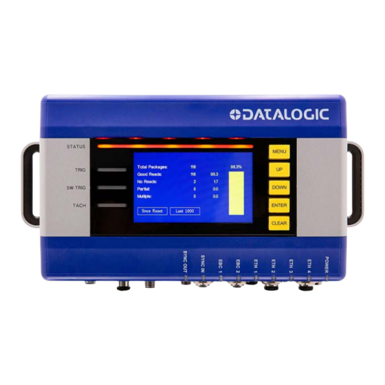
GENERAL VIEW 1. Status LED 2. 5 inch graphical color display 3. 5 key keypad 4. Mounting Handles 5. 9 LEDs 6. 2 CBX box connections 7. Profinet models port X1.P2 8. Profinet models port X1.P1 9. Sync Out 10. Sync In 11. -
Page 22: System Signal Leds
Ether Port Activity 10 Mbps Speed No Ethernet Connection KEYPAD AND DISPLAY The SC5100 display shows different messages according to the following operating modes. Use the SC5100 keypad to scroll through the windows or navigate in the menu. Symbols Meaning Menu... -
Page 23: Menu Functions And Navigation
Menu Functions and Navigation The five yellow display buttons are used to navigate between display options and to access additional details within each display option. When starting the SC5100, press to see the all of the display options; they are: MENU... - Page 24 The box around a device will turn green to indicate if that device read a barcode on the most recent package. By pressing Up/Down, an indicator box allows the selection of a “device” in order to see the device name. Below are Dashboards of a Redundant System showing the Primary Active and Backup Standby controllers. SC5100 CONTROLLER...
- Page 25 KEYPAD AND DISPLAY READ RATE This display shows the overall read rate of the system. Both the read rate for the last 1000 packages and the read rate since the last 'reset' are available. The Up/Down buttons are used to switch the display between the two sets of statistics. The read rate is reset of a power cycle, parameter update or if rest from the e-Genius or the Utilities display.
- Page 26 INTRODUCTION ERRORS This displays is a list of all currently active errors and warnings. The Up/Down buttons are used to switch between errors and warnings. Example errors from a Redundant system. SC5100 CONTROLLER...
-
Page 27: Bar Codes
KEYPAD AND DISPLAY BARCODES Displays a line for each barcode, with package sequence number and read position. If there are multiple codes per package, the sequence number is repeated. TX MSGS This option displays the complete transmitted message. Press to scroll Down through the ports to monitor messages on each port. - Page 28 This option displays all messages received (protocol index), along with package assign- ment and indication of “placed location”. Press to scroll through the various Down sources of data to monitor each. NETWORK This options displays the IP address and network assignments for the Ethernet ports. SC5100 CONTROLLER...
- Page 29 KEYPAD AND DISPLAY This option displays the input/outputs from the CBX units connected to the SC5100. Included with this information is the time, temperature, and tachometer count. SOFTWARE This option displays the software version, FPGA version and external alibi version (and checksum).
- Page 30 Use Up/Down keys to select the utility. Perform a Backup or Restore for the DS5000 using the SC5100 keypad. Go to Utilities, select DS5k and select Backup or Restore.
-
Page 31: Checking The Scanners Are Reading With Sc5100 Display
CHECKING THE SCANNERS ARE READING WITH SC5100 DISPLAY You can verify that the Scanners are reading by using your Primary SC5100 display. Sim- ply run a package through the system. screen displays the Scanners 2 (B) and 9 (I) that have read the barcode. -
Page 32: Sc5100 Versions
935750012 SC5100-102N Alibi Profinet 935750013 SC5100-102B Alibi Profibus 935750014 Accessories The following accessories are available on request for the SC5100 Controller. Description Material CAB-GE01 M12-IP67 TO RJ45 1M 93A050034 Gigabit Ethernet M12M-RJ45M CAB-GE03 M12-IP67 TO RJ45 3M 93A050035 Gigabit Ethernet M12M-RJ45M... - Page 33 CHECKING THE SCANNERS ARE READING WITH SC5100 DISPLAY CAB-ETH-M10 M12-IP67 ETHERNET CABLE 10M 93A051391 Profinet Cable (M12M 4P - RJ45) .5 M 5P Male Trigger and CAB-51TE M12F TRIG-ENC to SC5100 0.5M 93A050145 Encoder to SC5100 25P 100 Mb M12M to RJ45 FEMALE CBL-1534-0.2 ADAPT.
- Page 34 CBX510 CONNECTION BOX MODULAR 93A301087 CBX500 CONNECTION BOX MODULAR 93A301068 CBX100 CONNECTION BOX COMPACT 93A301067 Connection Cable SC5100 to CBX510 93A050071 SC5100/SC5100 CBX cable, 1 m CAB-DS01-S M12-IP67 TO CBX 1M 93A050058 M12F 17P to 25P M CBX CAB-DS03-S M12-IP67 TO CBX 3M...
-
Page 35: Guide To Installation
12. Verify the frame rate and/or maximum lines per inch is set correctly. These values appear on the SC5100 SyncNet Devices page. For some older camera software they are settable on the SC5100; if they are grayed out they are set on the camera (as in a normal camera installation). -
Page 36: Chapter 2. Mechanical Installation
Check the contents of the shipping cartons against the packing list. • Record all product serial numbers. UNPACKING INSTRUCTIONS Verify that the SC5100 Controller and all the parts supplied with the controller are pres- ent and intact when opening the packaging; the list of parts includes: • SC5100 Controller •... -
Page 37: Installation Sequence
To install the SC5100 follow the given procedure: 1. Select the mounting location and mount the SC5100 Controller. 2. Select the preferred power source to power the SC5100 via the M12 5P connector. “SC5100 Electrical Connections” on page 25. Dimensions and Clearances Make sure to provide 300 mm (12 in) clearance around the SC5100. -
Page 38: Mechanical Mounting
MECHANICAL INSTALLATION Mechanical Mounting SC5100 can be mounted to a Bosch or 80/20® frame. Follow the steps outlined below: Drop T-Slot stud into slot of 80/20 or Bosch structure (M8 thread or 5/16”-18). Place SC5100 Back Cover Spacer into place over T-stud. -
Page 39: Chapter 3. Electrical Installation
IMPORTANT: The SC5100 contain electronics that may be affected by elec- trostatic discharge (ESD). To prevent personal injury or damage to the unit, please follow the safety precautions and warnings found in the References section at the beginning of this manual. -
Page 40: Connecting An Sc5100 Controller
General Electrical Installation Precautions It is important to follow these general precautions when installaing, setting up, operat- ing, maintaining, troubleshooting or replacing any Datalogic products, parts or related equipment. As you plan and install your controller be sure to keep the following guide- lines in mind. - Page 41 CONNECTING AN SC5100 CONTROLLER ESD CAUTION: Ground the mounting structure to safety ground (protective earth ground (PE). See“Grounding” on page 57 for wiring recommenda- tions for safety ground. WARNING: If a connector is not in use, it should always be covered with its protective cap.
-
Page 42: Sc5100 Electrical Connections
13. USB - General USB A 2.0 connections Connecting a PC to the SC5100 During initial setup a PC or laptop may be connected to the SC5100. Connect an Ether- net cable to Ethernet 4, the default Configuration port of the SC5100, to your PC Ether- net port. -
Page 43: Power Connector Pin-Out Table
A CBX connection box provides flexible connectivity to a range of I/O devices and serial hosting. The SC5100 connects to two CBX boxes via I/O ports using 25-pin DSUB male to 25-pin female cables. - Page 44 RS485 IN TX- ETNERNET TX+ ETHERNET RX+ ETNERNET TX- RS485 IN RX+ ETHERNET RX- SYNC OUT M12 5P MALE FUNCTION RS485 OUT TX- RS485 OUT RX+ RS485 OUT RX- ETNERNET RX+ ETHERNET TX+ ETNERNET RX- RS485 OUT TX+ ETHERNET TX- SC5100 CONTROLLER...
-
Page 45: Ethernet Interface
CONNECTING AN SC5100 CONTROLLER Ethernet Interface Two standard EBC M12 4 pole D-Coded female connectors are provided on the SC5100 for Ethernet connections, labeled EBC1 and EBC2. These are reserved for building EBC clusters, typically cluster members are DS8110 and DX8210 scanners. This interface is IEEE 802.3 10 BaseT and IEEE 902.3u 100 Base Tx compliant. -
Page 46: Usb
The Profibus interface is only available in the SC5100-100B and SC5100-102B Profibus model and allows inserting the controller in a Profibus network. A pair of Male and Female M12 5-pin B-Coded connectors are provided on the SC5100’s right-most front panel for Profibus connections. -
Page 47: Profinet Interface
OFF. Profinet Interface The Profinet interface is only available in the SC5100-100N and SC5100-102N Profinet model and allows inserting the controller in a Profinet-IO network. Two standard M12 4-pin D-Coded female connectors are provided on the SC5100’s rightmost front panel for Profinet connections. -
Page 48: Selecting The Correct Cbx Connection Box For Your Application
Typical applications require a single CBX connection box to connect the trigger and encoder inputs to the controller. The SC5100 controller sources power to these devices. Other possible CBX connections are for digital outputs or a serial host. The CBX100 and- CBX510 each provide different input and output signals. -
Page 49: Cbx Connection Box Initial Configuration
CBX CONNECTION BOX INITIAL CONFIGURATION CBX CONNECTION BOX INITIAL CONFIGURATION Complete installation information on these connection boxes is available in the available at www.datalogic.com. Box Installation Manuals WARNING: If you are terminating more than one wire in a single terminal, cut off any tinned ends and twist the wires together before inserting them into the terminal. -
Page 50: Photoelectric Sensor Connections To Cbx510
Barcode scanning applications often use a Datalogic photoelectric sensor as a trigger device. The photoelectric sensor is wired directly into the CBX510 terminal block. If your application uses a trigger other than the one specified by Datalogic, follow the appropri- ate wiring diagram. -
Page 51: Photoelectric Sensor To Cbx510 (Pnp)
CBX CONNECTION BOX INITIAL CONFIGURATION Photoelectric Sensor to CBX510 (PNP) The following diagram illustrates standard recommended wiring of the Photoelectric PNP sensor in an SC5100 application to the CBX510. PRODUCT REFERENCE GUIDE... -
Page 52: Vdc Input (From Plc)
ELECTRICAL INSTALLATION 24 VDC Input (from PLC) The following diagram illustrates standard recommended wiring from a PLC to the CBX 510 in an SC5100 application. SC5100 CONTROLLER... -
Page 53: Encoder/Tachometer Wiring To Cbx510
NOTE: The Encoder/Tachometer signal can only be configured on CBX Port1 of the SC5100. Therefore the Encoder/Tachometer must be connected to the CBX connected to the SC5100 Port 1. Encoder/Tachometer Wiring for NPN Output to CBX510... -
Page 54: Encoder/Tachometer Wiring For Pnp Output To Cbx510
ELECTRICAL INSTALLATION Encoder/Tachometer Wiring for PNP Output to CBX510 NOTE: Some Photocraft tachometers may have a different color coding: (+V) Red or White/Orange (Signal) White or White/Blue (Ground) Black or Orange/White SC5100 CONTROLLER... -
Page 55: Serial Communication Wiring To Cbx510
PNP communications. The switch settings are shown below. Serial Communication Wiring to CBX510 The SC5100 provides serial RS232/RS422 communications to other devices through the CBX510. Each 25 pole DSUB port provides connection for RS232/RS422 communica- tions. - Page 56 ELECTRICAL INSTALLATION SC5100 CONTROLLER...
-
Page 57: Rs422Fd Host (Full Duplex)
CBX CONNECTION BOX INITIAL CONFIGURATION RS422FD HOST (Full Duplex) Use RS422 for a direct connection to a controller, personal computer, or other device. RS422 provides point-to-point communications at distances up to 1200 M [3940 ft]. Full duplex wiring supports a four wire, double twisted pair RxD/TxD. The Signal GND and shield cables are also required as shown. -
Page 58: Digital Output Configuration From Cbx510
Collector Current (pulse) 130 mA Max. Collector Current (continuous) 40 mA Max. Saturation Voltage (VCE) 1V at 10 mA Max. Max. Power Dissipation 90 mW at 50 degrees C ambient temperature. Schematics for Isolated and Non-Isolated digital outputs are provided below. SC5100 CONTROLLER... -
Page 59: Unpowered Outputs
CBX CONNECTION BOX INITIAL CONFIGURATION Unpowered Outputs Powered Outputs PRODUCT REFERENCE GUIDE... -
Page 60: General Use Digital Input Configuration From Cbx510
The CBX510 includes two general purpose isolated inputs, INPUT3 and INPUT/OUT- PUT4. INPUT4 is shared with OUTPUT4 so it must be configured using e-Genius soft- ware. If a second CBX is connected to CBX Port 2 on the SC5100, all inputs on the secondary CBX become general use inputs. -
Page 61: Trigger And Focusing Device Wiring
An external device can be used to trigger and/or measure the position of parcels as they enter the Field of view of a bar code reading system. This information is used by the sys- tem to determine the correct position for optimal focusing. The Datalogic focusing devices may be one of the following: •... -
Page 62: Dk503 - S-85 Position Sensor
ELECTRICAL INSTALLATION DK503 - S-85 Position Sensor When using the S-85 for focusing, it must be wired to the CBX510 connected to the SC5100 using the cable included in the kit (95ACC1620). SC5100 CONTROLLER... -
Page 63: Cbx100
TRIGGER AND FOCUSING DEVICE WIRING CBX100 Please verify that the CBX100 connection box is configured for the SC5100 application as follows: Reference the image and diagram above: 1. Set RS422HD TERM switch to OFF. 2. Set POWER SUPPLY jumper to FROM DEVICE. -
Page 64: Photoelectric Sensor Connections To Cbx100
Barcode scanning applications may use a Datalogic photoelectric sensor as a trigger device. The photoelectric sensor is wired directly into the CBX100 terminal block. If your application uses a trigger other than the one specified by Datalogic, follow the appropriate wiring diagram to assure proper wiring. -
Page 65: Photoelectric Sensor To Cbx100 (Npn)
TRIGGER AND FOCUSING DEVICE WIRING Photoelectric Sensor to CBX100 (NPN) The following diagram illustrates standard recommended NPN wiring of the Photoelec- tric sensor to a CBX100 Connector box in an SC5100 application. PRODUCT REFERENCE GUIDE... -
Page 66: Photoelectric Sensor To Cbx100 (Pnp)
ELECTRICAL INSTALLATION Photoelectric Sensor to CBX100 (PNP) The following diagram illustrates standard recommended wiring of the PNP Photoelec- tric sensor to a CBX100 Connector box in an SC5100 application. SC5100 CONTROLLER... -
Page 67: As1 Area Sensor To Cbx100 Connections
The AS1 area sensors can detect and provide trigger for very small or irregularly shaped objects. The following diagram illustrates standard recommended wiring of the AS1 Area Sensor to a CBX100 Connector box in an SC5100 application. PRODUCT REFERENCE GUIDE... -
Page 68: Encoder/Tachometer Wiring To Cbx100
ELECTRICAL INSTALLATION Encoder/Tachometer Wiring to CBX100 SC5100 applications over a conveyor belt use an accessory tachometer and mounting kit. Use the cable provided with the tach to connect to the CBX terminal block as shown below. NOTE: The Encoder/Tachometer signal can only be configured on CBX Port 1 of the SC5100. -
Page 69: Encoder/Tachometer Wiring For Pnp Output To Cbx100
TRIGGER AND FOCUSING DEVICE WIRING Encoder/Tachometer Wiring for PNP Output to CBX100 NOTE: Some Photocraft tachometers may have a different color coding: (+V) Red or White/Orange (Signal) White or White/Blue (Ground) Black or Orange/White PRODUCT REFERENCE GUIDE... -
Page 70: Serial Communication Wiring To Cbx100
ELECTRICAL INSTALLATION Serial Communication Wiring to CBX100 The SC5100 provides serial RS232/RS422 communications to other devices through the CBX100. Each 25 pole DSUB port provides connection for RS232/RS422 communica- tions. • RS232 provides point-to-point communications at distances up to 15 M [50 ft]. -
Page 71: Rs422Fd Host (Full Duplex)
TRIGGER AND FOCUSING DEVICE WIRING RS422FD HOST (Full Duplex) Use RS422 for a direct connection to a controller, personal computer, or other device. RS422 provides point-to-point communications at distances up to 1200 M [3940 ft]. Full duplex wiring supports a four wire, double twisted pair RxD/TxD. The Signal GND and shield cables are also required as shown. -
Page 72: Auxiliary Serial
The 9-pin connector is normally used for quick/temporary connection. For a more per- manent connection you can also use the CBX Box’s spring clamp connectors, in particu- lar the positions labeled RX, AUX, TX, AUX and SGND AUX. SC5100 CONTROLLER... -
Page 73: Digital Output Configuration For Cbx100
TRIGGER AND FOCUSING DEVICE WIRING Digital Output Configuration for CBX100 The CBX100 includes an OUTPUTS block for wiring relays as needed for external acces- sories. e-Genius Modify | Relays window includes options for outputs 1 and 2 including Life Light, Trigger Output, Error Light, Ready Light, Good Dim, and No Dim. Schematics for Isolated and Non-Isolated relays are provided below. -
Page 74: Grounding
4. Normally, steps 1 through 3 will guarantee proper function. In case of problems such as transmission of strange or wrong characters, devices stop working without any reason, or other unexpected behavior, try connecting the CBX or Controller Earth terminal to the PE terminal inside the PWR box. SC5100 CONTROLLER... -
Page 75: Typical Connection Block Diagrams
6.5 mm (.25 in) of aluminum use steel conduit and 25 mm (1 in.) gap Large Synchronized Network Layout An SC5100 can be used when building a large local EBC (Ethernet Based Connectivity) network. The SC5100 unit acts as the system master and is connected to the host through one of its interfaces. •... -
Page 76: Sc5100 Basic Layout 1
ELECTRICAL INSTALLATION SC5100 Basic Layout 1 SC5100 CONTROLLER... -
Page 77: Sc5100 Basic Layout 2
TYPICAL CONNECTION BLOCK DIAGRAMS SC5100 Basic Layout 2 PRODUCT REFERENCE GUIDE... -
Page 78: Sc5100 Basic Layout 4
ELECTRICAL INSTALLATION SC5100 Basic Layout 3 NOTE: Only a single SyncNet connection is required between SC5100’s with no SyncNet devices. SC5100 CONTROLLER... - Page 79 TYPICAL CONNECTION BLOCK DIAGRAMS SC5100 Basic Layout 4 For some applications you use the SC5100 without a CBX. For example, a system with three DS8110s and two DS5100s. You can connect the encoder and trigger devices directly to the SC5100 using the cable 821012230 as shown below.
- Page 80 ELECTRICAL INSTALLATION SC5100 CONTROLLER...
-
Page 81: Sc5100 Layout Using Dm3610 For Focus
TYPICAL CONNECTION BLOCK DIAGRAMS SC5100 Layout Using DM3610 for Focus PRODUCT REFERENCE GUIDE... -
Page 82: Chapter 4. Redundant And Bidirectonal Systems
Redundant System Layout NOTE: Operating Mode must be set to PackTrack. A redundant system provides additional reliability in the case of SC5100 failure. It can be configured with two SC5100 Controllers used together each with their respective power supply units. All other devices are distributed equally between the PWR units. One of... - Page 83 REDUNDANT AND BIDIRECTONAL SYSTEMS SC5100: Redundant System Layout with EBC and SyncNet SC5100 CONTROLLER...
-
Page 84: Configuring A Redundant System
ETH CAB-GE10 M12-IP67 to RJ45 10M. If the CFG port is taken, the HOST port can be used. 2. Turn on your computer. 3. Open a web browser and enter the IP address for the Primary SC5100 Controller. If the correct IP address is entered, the Log On window appears. The... -
Page 85: Organize Device Positions
, drop-down options appear for each device within the Reassign network. 4. Select a correct device number for the specified device. 5. Once you have properly assigned all positions and entered all descriptions, click by the Reassign option to save your re-assignments. SC5100 CONTROLLER... -
Page 86: Define Remaining Parameters
DEFINE SYSTEM PARAMETERS Define Remaining Parameters Use e-Genius to define all of the parameters for the SC5100 Primary Controller as well as the Devices connected to the controllers. See the product specific Reference Guides for each product for parameter details. -
Page 87: Load Parameter File To Backup Sc5100
Application drop-down. 7. Click to save these parameter settings to your Backup SC5100. Enter REDS Settings on SC5100 Keypads On the keypad of each SC5100 you must specify which is the controller and Primary which is the controller. -
Page 88: Power Off System
Clear Utilities Power Off System Power off the entire system. Connect ALL Devices Now connect the Backup SC5100 to the EBC network and make all other system connec- tions. Power-up System Power Up the system. PRODUCT REFERENCE GUIDE... -
Page 89: Check Status Of Primary And Backup Sc5100
REDUNDANT AND BIDIRECTONAL SYSTEMS CHECK STATUS OF PRIMARY AND BACKUP SC5100 The LEDs on the SC5100 should operate as listed below when the system is operating as it should. SC5100 LEDs STATUS= Light Green TRIG = Light Green (when Photocells are triggered) -
Page 90: Setting Up Redundant Operation
SETTING UP REDUNDANT OPERATION After completing the preceding steps, you must now make sure Redundancy settings are correct for each SC5100. Again your Eth 4 port of each SC5100 must be connected to your computer and you must enter e-Genius. - Page 91 Percentage Package Lost Threshold Enter the percentage (number out of 100 packages counted) recognized by the Stand-by SC5100 but not by the Active SC5100, (the active controller is losing a percentage of packages), after which the Redundancy Role is exchanged.
- Page 92 SETTING UP REDUNDANT OPERATION Lost Heartbeat Response Enable/Disable The heartbeat monitor can be enabled to check for the host connection to ‘echo’ a response to each heartbeat message. If enabled, an error is generated if the specified number of messages is missed.
-
Page 93: Bidirectional Setup
REDUNDANT AND BIDIRECTONAL SYSTEMS BIDIRECTIONAL SETUP A Datalogic Bidirectional system is a system that accommodates an application where the customer can change the direction of the conveyor. To accommodate a Bidirectional system an additional photocell is required, as well as other special equipment and spe- cific software settings. - Page 94 Enter a value to specify the amount of time after a direction change, before another direction change is allowed. NOTE: While the direction change is “locked out” the SC5100 display and Monitor page show the direction with {*} appended to it.
- Page 95 1. When you have finished making changes, click to save all pending Update All changes, click to revert to all previously saved values, and click Reset All Reset to revert to previous saved values on the current page. Page SC5100 CONTROLLER...
-
Page 96: Chapter 6. Maintenance
Replacing an SC5100 The SC5100 stores the system configuration and software on the externally accessible SD card. When replacing an SC5100 this card can just be moved to the new unit. In case of SC5100 failure, proceed as follows: 1. Disconnect power from the device. - Page 97 4. Connect the new SC5100 to the system. 5. Insert the SD Card. 6. Close and secure the access panel of the replacement SC5100. Make sure not to insert the SD card upside down. Carefully insert it in the guides, so that it will not fall inside the device. Gently push it into the slot.
-
Page 98: Chapter 7. Troubleshooting
For further information on training, contact us through the Datalogic web- site at www.datalogic.com. NOTE: When contacting Datalogic for help with any device, please be ready to share the unit serial number with the Datalogic technician. The unit’s serial number tag is located on the device, where shown below. Help desk contact information is available at www.datalogic.com. -
Page 99: Troubleshooting Guides
TROUBLESHOOTING TROUBLESHOOTING GUIDES Online Mode - NO READ SC5100 CONTROLLER... -
Page 100: Packtrack Mode - No Read
TROUBLESHOOTING GUIDES PackTrack Mode - NO READ PRODUCT REFERENCE GUIDE... -
Page 101: Online Mode - No Read Message
TROUBLESHOOTING Online Mode - NO READ MESSAGE SC5100 CONTROLLER... -
Page 102: Packtrack Mode - No Read Message
TROUBLESHOOTING GUIDES PackTrack Mode - NO READ MESSAGE PRODUCT REFERENCE GUIDE... -
Page 103: Low Read Rate
TROUBLESHOOTING Low Read Rate SC5100 CONTROLLER... -
Page 104: Error Codes And Resolutions
ERROR CODES AND RESOLUTIONS ERROR CODES AND RESOLUTIONS Error Action Description Severity Explanation Symptom Troubleshooting Code required In a tunnel configu- ration, the cabling In a Master/ that connects the Slave configura- Make sure cables system into to a The scanning tion, the Master are connected. - Page 105 Replace the pho- (PackTrack tionality of the pho- toelectric sensor. transmitted to Mode). the Host. toelectric sensor. No Phase "time- out" is exceeded (On-Line and PackTrack Mode). Trigger must be No Phase Error Error identified within a speci- fied time. SC5100 CONTROLLER...
- Page 106 Redundancy exchange of the Role Exchange Warning Redundancy Role Warning is in progress. The Master Stand- by SC5100 does not work OR an encoder or pres- ence sensor error Redundancy Redundancy is is gener ated on Error Warning not available.
- Page 107 PWR power Power Failure Error supply. A presence sen- sor warning has occurred only on the Stand-by SC5100 of the redundant sys- Presence Sen- Error tem and is trans- sor Failure mitted by the Active SC5100. An encoder...
- Page 108 ERROR CODES AND RESOLUTIONS Protocol Index message not Main Serial Port received on Main Error Error Serial Port. Protocol Index message not Aux Serial Port received on Aux Error Error Serial Port. Protocol Index message not Ethernet Socket received on User Error 1 Error Socket 1.
- Page 109 APD Tempera- scanner moni- ner and moni- tor it Error start miss- ing ture Error tors the tem- to determine the transmit Replace scanner. perature, and if it whether the error point. is erratic, this reoccurs. error is posted. SC5100 CONTROLLER...
- Page 110 ERROR CODES AND RESOLUTIONS The scanner has an in-the-beam sensor, which provides timing Put the scanner in for the decoding This is an inter- the test mode to nal failure and is of barcodes. The test its ability to scanner moni- not field ser- read the barcode The scanner...
- Page 111 Use the scanner The system test mode to con- When the experiences a firm that the scan- SC5100 is used, higher no-read ner can statically the scanner rate. reading a barcode internal net- (see “Diagnostics |...
-
Page 112: Chapter 8. Technical Features
1200 to 115200 bits/s Ethernet (x2) TCP/IP 4 Ports Gb/s ETH Switch; Embedded EtherNet/IP EBC and SyncNet Internal Network 100 Mbit/s Alibi Storage (only SC5100-102x mod- “Legal For Trade” Alibi Storage for Scale Weight Data els) Fieldbus - Profibus (only SC5100-1100 model) PROFIBUS DP application protocol;... - Page 113 IP65* PHYSICAL FEATURES Mechanical Dimensions 349 x175 x 89 mm (13.75 x 6.89 x 3.5 in) Weight 1.94 kg (4.3 lb) *When all the M12 connectors and reading devices are correctly connected (or closed with proper protection caps). SC5100 CONTROLLER...
-
Page 114: Appendix A. Scale Alibi Storage
• “Step 1” on page 97 • “Step 2” on page 98 • “Step 3” on page 99 • “Formatting Metter Toledo Scale Messages” on page 99 • “Formatting OCS Scale Messages” on page 100 SC5100 CONTROLLER... -
Page 115: Step 1
Sockets User Sockets 2. Add a new that matches that of your device. This allows the User Socket Scale SC5100 to receive messages from the scale. 3. Select the and enter the Type: Server Protocol: TCP Port: 51236 SC5100 CONTROLLER... -
Page 116: Step 2
SCALE ALIBI STORAGE INTRODUCTION Step 2 Step 2 requires you to define the communication with the scale. You do this by setting up a message using the Protocol Index To Edit Protocol Index Settings: 1. In the menu under , select Modify Settings / Controller Settings / Messaging . -
Page 117: Step 3
• <units> should be g or kg (for grams or kilograms). • <Weight> should be a number with a decimal point for kilograms and no decimal point for grams. • <scale number> should be 1, 2 or 3 SC5100 CONTROLLER... -
Page 118: Formatting Ocs Scale Messages
FORMATTING OCS SCALE MESSAGES Units, weight and scale number can be pretty much any asci string that does not contain spaces. FORMATTING OCS SCALE MESSAGES This scale works from 0 to 60000g, but the LFT range is from 250g to 40000g. This means that when we get weights out of LFT range, the value is without unit (g) and the Item Attribute is “F020”... -
Page 119: Appendix B. Ethernet/Ip
EIP. EIP simplifies the communication of barcode and Input/Output data with other EIP enabled devices, such as a programmable logic controller (PLC). Software release 1.3.0.0 and higher for the DS8110, DX8210, SC5100 product line sup- ports the legacy ASI EtherNet/IP™ Object. This mode allows the installation of DS8110,... - Page 120 ETHERNET/IP NOTE: Contact Datalogic Support for information on setting up ASI Objects (legacy Accu-Sort Devices). Once enabled, EIP allows the reader to communicate with other Ethernet/IP enabled devices. This can be done using and a special proto- Explicit Messaging, I/O Messaging...
- Page 121 Operating Mode page of e-Genius. When this is enabled, the reader trigger input is ignored and the reader will be triggered solely by manipulating the Trigger Bit in the Output Word (contained in the reader Assembly and Output Objects). SC5100 CONTROLLER...
-
Page 122: I/O Controllogix Messaging Example
When EtherNet/IP is enabled on the reader, EIP I/O Messaging is automatically enabled. No further configuration on the Datalogic device is needed to setup I/O messaging. Since the ControlLogix processor now treats the reader as an I/O device, to setup an EIP I/O message transfer between an reader and a ControlLogix processor, you need to con- figure your reader as a Generic Ethernet Module in the ControlLogix I/O tree. - Page 123 6. You can only “schedule” I/O message transfers to the reader at a fixed interval. Click the and specify this interval. The reader will handle intervals Connection Tab down to 10 milliseconds; however, intervals this small may begin to affect the overall reader performance. SC5100 CONTROLLER...
-
Page 124: Reader:c Configuration Data
ETHERNET/IP 7. Click 8. After the module definition for the reader has been completed, tags will be cre- ated in the controller based on the name you specified for this reader on the prop- erties page for the module. These tags will consist of the name followed either by the letter “Reader:C Configuration Data”... -
Page 125: Discrete Input Word
(output register is not equal to input) the rung is executed. The Copy File instruction copies the bar code data to a program tag. Note that in this example the instruction moves a fixed 10 registers (10 registers will contain 20 ASCII characters). SC5100 CONTROLLER... -
Page 126: On-Demand Messaging (Controllogix)
ON-DEMAND MESSAGING (CONTROLLOGIX) The Move instruction moves the sequence number from the input registers to the out- put register. This lets the reader know the PLC is ready for the data from the next read cycle. ON-DEMAND MESSAGING (CONTROLLOGIX) On-Demand messaging provides another option for transferring bar code data to your ControlLogix processor. -
Page 127: On-Demand Tag
The following table has a description of all of the data types used. USINT Unsigned Short Integer (8-bit) UINT Unsigned Integer (16-bit) UDINT Unsigned Double Integer (32-bit) STRING Character String (1 byte per character) BYTE Bit String (8-bits) WORD Bit String (16-bits) DWORD Bit String (32-bits) SC5100 CONTROLLER... -
Page 128: Standard Objects
STANDARD OBJECTS STANDARD OBJECTS Identity Object (01HEX - 1 Instance) Class Attributes Attribute ID Name Data Type Data Value Access Rule Revision UINT Instance Attributes Attribute ID Name Data Type Data Value Access Rule Vendor Number UINT 25DEC Device Type UINT 00HEX 0x00 –... -
Page 129: Message Router Object (02Hex)
Reader Programmable Output #8 8-15 Unused Instance 0x70 Attributes (Output Instance 1) Default Attribute ID Name Data Type Access Rule Data Value Output Data Structure of: UINT Discrete Output Word Get / Set (see below) UINT Last Barcode Seq. Num Received SC5100 CONTROLLER... -
Page 130: Discrete Output Word
STANDARD OBJECTS Discrete Output Word Bit = 0 Bit = 1 Trigger Off Trigger On 1 – 7 Unused Unused Reader Relay #1 Off Reader Relay #1 On Reader Relay #2 Off Reader Relay #2 On Reader Relay #3 Off Reader Relay #3 On Reader Relay #4 Off Reader Relay #4 On... -
Page 131: Tcp Object (F5Hex - 1 Instance)
Host Name Size STRING Host Name Common Services Service Code Implemented for Service Name Class Level Instance Level Get_Attribute_Sin- 0EHEX Ethernet Link Object (F6 - 1 Instance) Class Attributes Attribute ID Name Data Type Data Value Access Rule Revision UINT SC5100 CONTROLLER... -
Page 132: Instance Attributes
STANDARD OBJECTS Instance Attributes Default Attribute ID Name Data Type Access Rule Data Value Interface Speed UDINT Interface Flags DWORD Physical Address USINT Array[6] Common Services Service Code Implemented for Service Name Class Level Instance Level Get_Attribute_Sin- 0EHEX VENDOR SPECIFIC OBJECTS Barcode Data Object (70 - 1 Instance) Class Attributes... -
Page 133: Instance Attributes
Reader Programmable Output #4 Reader Programmable Output #5 Reader Programmable Output #6 Reader Programmable Output #7 Reader Programmable Output #8 8-15 Unused Common Services Service Code Implemented for Service Name Class Level Instance Level 0EHEX Get Attribute Single SC5100 CONTROLLER... -
Page 134: Discrete Output Data Object (72 Hex - 1 Instance)
STANDARD OBJECTS Discrete Output Data Object (72 – 1 Instance) Class Attributes Attribute ID Name Data Type Data Value Access Rule Revision UINT Instance Attributes Default Attribute ID Name Data Type Access Rule Data Value Discrete Output UINT Get / Set Data Discrete Output Word Bit = 0... -
Page 135: Appendix C. Ebc Connection Module
Thanks to the EBC Connection Module™, Matrix readers and Laser Scanners can be con- nected to the same network as Slave devices using a SC5100 Controller as a Master. PACKAGE CONTENT Verify that the EBC Connection Module and all the parts supplied with the equipment are present and intact when opening the packaging. -
Page 136: General View
GENERAL VIEW GENERAL VIEW 1. EBC 1 connector and LED 4. Pigtail connector 2. PWR IN connector and LED 5. EXT ILL connector and LED 3. EBC 2 connector and LED 6. Mounting slots (6) MECHANICAL INSTALLATION The EBC Connection Module is intended to be installed on Bosch frames with common T-head bolts. -
Page 137: System Wiring/Cabling
These LEDs light up blue when power is properly applied to the EBC Connection Mod- ule. EBC 1 This LED blinks yellow when there is Link Activity on Port 1. EBC 2 This LED blinks yellow when there is Link Activity on Port 2. SC5100 CONTROLLER... -
Page 138: Electrical Connections
ELECTRICAL CONNECTIONS ELECTRICAL CONNECTIONS Pigtail connector - M12 17 poles female NAME DESCRIPTION 24 V power supply input voltage + for Matrix readers 24 V power supply input voltage - for Matrix readers RS232_RX AUX Serial RX OUT2 Digital Output 2 RS422_TXN MAIN Serial TX- RS422_TXP... - Page 139 24 V power supply input voltage + for Ext. Illuminator 24 V power supply input voltage - for Ext. Illuminator STROBE Strobe signal for External Illuminator Ethernet connector - M12 5 poles female NAME DESCRIPTION Ethernet TX+ Ethernet RX+ Ethernet TX- Ethernet RX- SC5100 CONTROLLER...
-
Page 140: Software Configuration
• entering the SC5100 IP address in the browser (default 192.168.1.100), OR • clicking on the SC5100 icon under the Device Selection menu in DL.CODE. Then log on to e-Genius (refer to the SC5100 Product Reference Guide for more information). -
Page 141: Accessories
93A050066 ETH Cable M12-M12 (Straight-Straight) - 5mt 93A050067 Illuminator cables CBL-1480-01 M12/5P MALE/FEMALE 1M IDNET 93A050049 CBL-1480-02 M12/5P MALE/FEMALE 2M IDNET 93A050050 *For a complete list of the available accessory cables, see the product page on www.data- logic.com. SC5100 CONTROLLER... -
Page 142: Typical Layouts
TYPICAL LAYOUTS TYPICAL LAYOUTS Large Synchronized Network Layout The SC5100 controller can be connected to the host in several different layouts, depending on the controller model and host interfaces. External devices (e.g. presence sensor, encoders) are all connected to the SC5100 through a CBX510 connection box using one of the two I/O connectors. -
Page 143: Com To Host
EBC CONNECTION MODULE™ COM to Host The host can be connected via COM (RS232 or RS422) to the controller through a CBX510. Fieldbus to Host The host can be connected to a SC5100 dedicated Fieldbus model. SC5100 CONTROLLER... -
Page 144: Ebc - Syncnet Mixed Layout
TYPICAL LAYOUTS EBC - Syncnet Mixed Layout The SC5100 controller allows compatible Slave devices to connect to a Syncnet Net- work. The EBC controller in this layout allows communication between Laser Scanners, AV readers and Matrix readers. PRODUCT REFERENCE GUIDE... -
Page 145: Redundant System Layout
PWR power supply units. The scanners are distributed equally between the PWR units. In this case, one of the controllers acts as a Working Master or active unit, while the other serves as a Protecting Master or backup unit. SC5100 CONTROLLER... -
Page 146: Redundant System Layout With Host Supporting Serial Com Communications
TYPICAL LAYOUTS Redundant System Layout with Host supporting Serial COM Communications A host that supports COM communications can be connected to the controller through a CBX510 (one for each controller). PRODUCT REFERENCE GUIDE... -
Page 147: Technical Specifications
2 EBC Links (Orange) PHYSICAL FEATURES H x W x L Dimensions 170 x 72 x 32 mm (6.7 x 2.8 x 1.3 in) Pigtail cable length 50 mm (2 in) Weight 435 g (15.3 oz) Material Aluminum SC5100 CONTROLLER... - Page 148 TECHNICAL SPECIFICATIONS ENVIRONMENTAL FEATURES Operating temperature -10 to 50 °C (+14 to 122 °F) Storage temperature -20 to 70 °C (-4 to 158 °F) Humidity max. 90% non condensing 14 mm @ 2 to 10 Hz; 1.5 mm @ 13 to 55 Hz; Sinusoidal vibration resistance EN 60068-2-6 2 gn @ 70 to 500 Hz;...
- Page 149 © 2024 Datalogic S.p.A. and /or its affiliates • All rights reserved • Without limiting the rights under copyright, no part of this documentation may be reproduced, stored in or introduced into a retrieval system, or transmitted in any form or by any means, or for any purpose, without the express written permission of Datalogic S.p.A.
Need help?
Do you have a question about the SC5100 and is the answer not in the manual?
Questions and answers