Table of Contents
Advertisement
Advertisement
Table of Contents

Related Manuals for Datalogic VS Series


Summary of Contents for Datalogic VS Series
- Page 1 > DataVS2 - VSM...
- Page 2 DataVS2 - VSM Instruction Manual Ed.: 12/2017 © 2011 - 2017 Datalogic S.p.A. and/or its affiliates ALL RIGHTS RESERVED. Without limiting the rights under copyright, no part of this documentation may be reproduced, stored in or introduced into a retrieval system, or transmitted in any form or by any means, or for any purpose, without the express written permission of Datalogic S.p.A.
-
Page 3: Table Of Contents
CONTENTS COMPLIANCE ......................v CE Compliance ......................v FCC Compliance ......................v GENERAL VIEW ......................vi GENERAL INFORMATION ..................1 Conventions Used in the Manual .................. 1 General Description ...................... 1 INSTALLATION ......................2 Safety Recommendations ..................... 2 DataVS2 VSM DIN Rail Mounting ................2 DataVS2 VSM Panel Mounting .................. - Page 4 8.3.5 Cancellation of a VSM Slot ..................27 8.3.6 Cancellation of a DataVS2 Slot .................. 28 8.3.7 Cancellation of all the VSM Slots ................28 8.3.8 Cancellation of all the DataVS2 Slots ................. 29 Factory Reset ......................29 Sensor List ........................31 Users ..........................
-
Page 5: Compliance
This evaluation was carried out in relation to the applicable points of the standards listed in the Declaration of Conformity. Datalogic products are mainly designed for integration purposes into more complex systems. For this reason it is under the responsibility of the system integrator to do a new risk assessment regarding the final installation. -
Page 6: General View
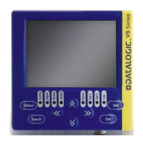
GENERAL VIEW DataVS2-VSM Figure A Monitor (color 3.5" LCD 320x240 pixel) ARROW Buttons Status LEDs Ethernet Network Connector STATUS Button ESC Button SET Button TEACH Button Power, OUT, ETH Link LEDs Power Supply Connector... -
Page 7: General Information
Thanks to the wide range of functions, the VSM represents an excellent and complete HMI interface, ideal for automatic production lines controlled by operators. The Datalogic DataVS2 vision sensor (machine vision) is easy to use and has advanced inspection functions which makes it very suitable to many different fields (quality control on production lines or automatic material handling are just a few examples). -
Page 8: Installation
DATAVS2-VSM INSTRUCTION MANUAL 2 INSTALLATION 2.1 SAFETY RECOMMENDATIONS Read the instruction manual carefully before installing the sensor and VSM. Make sure that the product is suitable for the system that you intend to set up. Connect the cables to the devices with the poles in the right direction. ... - Page 9 INSTALLATION Wedge the VSM unit in the DIN rail. First set the upper part of the monitor and then press down the lower part. Once inserted, block the VSM monitor using the two white side locking clips. DIN Guide...
-
Page 10: Datavs2 Vsm Panel Mounting
DATAVS2-VSM INSTRUCTION MANUAL 2.3 DATAVS2 VSM PANEL MOUNTING The VSM can also be installed on a panel. All the accessories for this mounting are included in the package. First, carefully place the rubber seal around the VSM unit. Rubber seal... - Page 11 INSTALLATION Then fix the VSM on the panel using the two locking screws and the two rubber caps. Locking screw R7.5 [R0.30] ±0.2 [3.62 ±0.01...
-
Page 12: Electrical Connections
DATAVS2-VSM INSTRUCTION MANUAL 3 ELECTRICAL CONNECTIONS 3.1 PINOUTS 3.1.1 DataVS2 OBJ/AOR Sensor M12 Reverse Keyed 4-Pin Male M12 8-Pin Male (Ethernet connection) (power supply and I/O) pin 1: white : Digital Input 1 pin 1: Ethernet RX+ pin 2: brown: +24 Vdc pin 2: Ethernet TX+ pin 3: green : Output 4 / pin 3: Ethernet RX-... -
Page 13: Vsm Monitor
ELECTRICAL CONNECTIONS 3.1.3 VSM Monitor M12 4-Pin Male M12 Reverse Keyed 4-Pin Male (Power supply) (Ethernet connection) pin 1: +24 Vdc pin 1: Ethernet RX+ pin 2: Reserved pin 2: Ethernet TX+ pin 3: GROUND pin 3: Ethernet RX- pin 4: Reserved pin 4: Ethernet TX- 3.2 POINT-TO-POINT CONNECTION Connect DataVS2 to VSM using the specific connection cable (DataVS-CV-VSM-xx). -
Page 14: Ground Connection
DATAVS2-VSM INSTRUCTION MANUAL 3.4 GROUND CONNECTION To comply with the EMC requirements, the Ethernet cable shield has to be grounded. (Use the yellow/green cable supplied with the VSM). Washer M12 Ring Nut Insert the washer M12 on the yellow/green cable in the VSM connector and then screw the Ethernet cable until the ring nut reaches the washer. -
Page 15: First Approach To Vsm
FIRST APPROACH TO VSM 4 FIRST APPROACH TO VSM 4.1 INTRODUCTION The configuration of the DataVS2 vision sensor has to be made only through DataVS2 GUI. To simplify the instructions described in this manual, the pressing of the buttons on the VSM user interface will be indicated as follows: 4.2 VSM USER INTERFACE The chart shown below provides a general overview of the user interface on the VSM user... -
Page 16: Connection To Datavs2
DATAVS2-VSM INSTRUCTION MANUAL LED ID Colour Meaning Power Green VSM correctly powered Out 1 Orange Digital output 1 active Out 2 Orange Digital output 2 active Link Green VSM correctly connected to LAN Set/Net Green Current status: Setup Adjust Green Current status: Adjust Monitor Green... - Page 17 FIRST APPROACH TO VSM The maximum number of DataVS2 displayed in the list is 32. NOTE If no devices have been found in the first discovery, a new search can be carried-out by pressing TEACH. NOTE To connect a sensor, just select it from the list and press SET. Once connected, the VSM enters in the monitor status displaying the inspection currently being carried/out by the DataVS2.
-
Page 18: Monitoring An Inspection
DATAVS2-VSM INSTRUCTION MANUAL 5 MONITORING AN INSPECTION The “Monitor” mode allows the user to check the correct functioning of the inspection defined previously. The chart shown below provides a description of the main modes available and shows how to enable viewing. Mode Example Enable... -
Page 19: Inspection Change
INSPECTION CHANGE 6 INSPECTION CHANGE To change the inspection currently in execution on the DataVS2, the user must start from the monitor screen and press TEACH. The selection panel will be displayed: Press SET on “Change Current Inspection” to access another panel where the user can select the inspection to carry-out. -
Page 20: Inspection Parameter Change
DATAVS2-VSM INSTRUCTION MANUAL 7 INSPECTION PARAMETER CHANGE 7.1 CURRENT INSPECTION CHANGE To change the sensor parameters, press TEACH in the monitor mode. The following panel is displayed: At this point the user can choose to change the current inspection or modify the parameters. Selecting “Adjust Current Inspection”... -
Page 21: Camera Parameter Change
INSPECTION PARAMETER CHANGE 7.2 CAMERA PARAMETER CHANGE Selecting the “Camera” option and pressing SET, the user accesses some DataVS2 parameters such as: exposure time, gain and illuminator operating mode. The user can change the focus between the objects on the panel by using the UP/DOWN ARROWS. - Page 22 DATAVS2-VSM INSTRUCTION MANUAL If no other change has to be made, press ESC to return to the “Monitor” status. If inspection parameters have been changed, another panel will be displayed requesting the saving of the changes: To save the new data in the memory select “Save and Exit” using the SET button. If the changes must have to be cancelled, select “Exit without Saving”...
-
Page 23: Tool Parameters Change
INSPECTION PARAMETER CHANGE 7.3 TOOL PARAMETERS CHANGE 7.3.1 Tool Selection Press SET on the “Tools” icon in the “Adjust Current Inspection” panel. The “Tool Selection” panel is displayed and the user can choose the tools to use. All the inspection tools will be displayed one at time according to the creation order. The user can scroll through the different tools using the RIGHT/LEFT ARROWS. -
Page 24: Roi Change
DATAVS2-VSM INSTRUCTION MANUAL 7.3.2 ROI Change To modify a ROI, the tool must have been selected previously and the “Adjust Tools” panel opened. The following operations are possible: Move, Resize and Rotate. For the tools characterized by two ROIs, such as the Pattern Match or 360° Pattern Match, the VSM allows editing only the ROI research. - Page 25 INSPECTION PARAMETER CHANGE Once you have achieved the desired size, press the TEACH button to save the settings and return to the Setup menu. Press the ESC button to return to the Setup menu without saving the modifications (the system will request confirmation on the saving option). ROTATE: To rotate the ROI, select the “Rotate”...
-
Page 26: Other Parameter Changes Of The Selected Tool
DATAVS2-VSM INSTRUCTION MANUAL 7.3.3 Other Parameter Changes of the Selected Tool This paragraph explains how to change the parameters that adjust the functioning of a tool. The VSM monitor is divided as follows: the parameters that the user can change are displayed on the right side, while the image captured by the sensor is displayed on the remaining area. -
Page 27: Reference Image Change
INSPECTION PARAMETER CHANGE 7.4 REFERENCE IMAGE CHANGE Select "Reference" and press SET to access the management screen of the reference image. The screen shows the current image, pressing TEACH you can activate the reference image change procedure. After the press of TEACH button the first acquired image will be set as new reference image of the current inspection. -
Page 28: Trigger Mode Change
DATAVS2-VSM INSTRUCTION MANUAL 7.5 TRIGGER MODE CHANGE Select "Trigger" and press SET to access the management screen of the trigger mode. As you can see in the image, the VSM is split into two main areas: the parameters that the user can change are displayed on the right side of the monitor, while the remaining area displays the image acquired by the sensor. -
Page 29: Advanced Functions
ADVANCED FUNCTIONS 8 ADVANCED FUNCTIONS The previous chapter described the procedure used to modify an inspection for DataVS2. Further to the functions above-described, there are other user settings on the VSM monitor which can be accessed from the System menu. “System”... -
Page 30: Sensor Settings
DATAVS2-VSM INSTRUCTION MANUAL Restart the device to apply correctly the changes. NOTE To return to main panel without saving, press ESC. 8.2 SENSOR SETTINGS This panel, when a DataVS2 is connected, can display information such as name, firmware, Hardware revision, MAC and modify the sensor network parameters: IP, Netmask and DHCP... -
Page 31: Memory Management
ADVANCED FUNCTIONS 8.3 MEMORY MANAGEMENT This paragraph explains how to transfer or cancel a memory slot between VSM and DataVS2. At this point the user can select the “Memory Management” icon and press SET. The following panel is displayed: Memories of Memories of VSM DataVS2 Transfer... -
Page 32: Slot Selection (Datavs2)
DATAVS2-VSM INSTRUCTION MANUAL 8.3.2 Slot Selection (DataVS2) The slot selection is similar to the VSM one: the focus must be moved using the ARROWS on the “SENSOR” label and SET must be pressed. The focus will be moved inside the memory list and once chosen the desired one press SET to confirm. -
Page 33: Transfer From Datavs2 To Vsm
ADVANCED FUNCTIONS 8.3.4 Transfer from DataVS2 to VSM To transfer the memory slot from DataVS2 to VSM (after selecting both the source as well as the destination) move the focus on the “Arrow on Left” button and press SET. At this point the information label will request another operation confirmation, to proceed press ARROW UP, otherwise press ARROW DOWN to abandon. -
Page 34: Cancellation Of A Datavs2 Slot
DATAVS2-VSM INSTRUCTION MANUAL 8.3.6 Cancellation of a DataVS2 Slot Just like the VSM slots, the desired slot has to be selected (refer to previous paragraph “Selection of slot (DataVS2)”). Obviously the monitor must be connected to a sensor to access its memory. Then move the focus on “Delete Current”... -
Page 35: Cancellation Of All The Datavs2 Slots
ADVANCED FUNCTIONS Another confirmation will be requested. To proceed press ARROW UP otherwise, press ARROW DOWN to abandon. In both cases, the information label will display the operation result and a refresh of the panel names will be made. 8.3.8 Cancellation of all the DataVS2 Slots To cancel all the DataVS2 memory slots no specific slot has to be selected but the user must only move the focus on the “Delete ALL”... - Page 36 DATAVS2-VSM INSTRUCTION MANUAL The system reset requires the VSM restart and the loss of all the data stored in the memory. NOTE...
-
Page 37: Sensor List
ADVANCED FUNCTIONS 8.5 SENSOR LIST The “Sensor List” panel, after having made a discovery, lists the DataVS2 present in the subnet. To connect a sensor the user just has to select it from the list with the UP/DOWN ARROWS and press SET. Selected sensor Once the connection has been established, the VSM returns immediately to the monitor mode. - Page 38 DATAVS2-VSM INSTRUCTION MANUAL The account selection panel is displayed as follows: User typology Info on account Password field Information Label Each user logins in using the administrator account until a new password is memorised. NOTE To enable the administrator password, the user must access “Modify Account”, select “Admin”...
- Page 39 ADVANCED FUNCTIONS When the administrator password has been forgotten, the VSM can be unblocked with the recovery password ARROW UP, ARROW LEFT, ARROW RIGHT, ARROW RIGHT. At the end of the procedure remember to cancel the old password and set a new one in the “Modify Account” NOTE panel.
- Page 40 DATAVS2-VSM INSTRUCTION MANUAL In “Modify Account” mode the user has to select “Advanced” and then save a password. After this, the account will be active and only a part of the advanced functions enabled. Besides the basic rights, the inspection can be changed and the parameters of the relative tools modified.
-
Page 41: Removal Of The Password
ADVANCED FUNCTIONS 8.6.1 Removal of the Password To disable all the accounts and remove the administrator password, the user must log in as “Admin”. Access “Modify Account”, select “Admin” user and press SET. At this point the system requests the user to confirm the cancellation of the password. To confirm press ARROW UP. -
Page 42: Language
DATAVS2-VSM INSTRUCTION MANUAL 8.7 LANGUAGE Through this panel you can change the language of the VSM, current language is written in the upper right side of screen. To set up a new language, choose the one you want with the RIGHT/LEFT ARROW and press SET. -
Page 43: Datavs2 Gui Connection
DATAVS2 GUI CONNECTION 9 DATAVS2 GUI CONNECTION To connect the VSM to DataVS2 GUI the “On Line“ mode must be selected from the specific interface. After having selected the relative radio button, the following screen will appear: Parameters: Description DataVS2 GUI searches for all the connected Find sensor sensors/monitors and lists them in the CONTROL PANEL DataVS2 GUI will connect the sensor/monitor whose... -
Page 44: Vsm General Information
DATAVS2-VSM INSTRUCTION MANUAL The control panel will display a list of all the DataVS2/VSMs found by the “Find sensor” function. The following information will be shown for each device: The IP address; The name; An indication on the possibility of creating a connection (line highlighted in green) or not (line highlighted in red);... -
Page 45: Vsm Memory Settings
DATAVS2 GUI CONNECTION 9.2 VSM MEMORY SETTINGS This window shows the memory status of the VSM to which you are connected. It also allows you to save on VSM PC inspections by pressing the button "Save On VSM”; To save on PC the inspections saved on the memory of VSM by pressing the button "Save On PC";... -
Page 46: Firmware Update
DATAVS2-VSM INSTRUCTION MANUAL 9.3 FIRMWARE UPDATE The “VSM firmware updating” section can be accessed from the “VSM setting” panel and is displayed as follows:... - Page 47 DATAVS2 GUI CONNECTION Parameters: Description Version of Firmware currently executed on the connected Current Firmware VSM. Press this button to select the Firmware file to be loaded on the sensor. A dialogue window will then allow the user to choose the “Desired Firmware” file saved in the PC. Choose File After selecting the desired firmware and pressing “OK”...
-
Page 48: Recovery Mode
DATAVS2-VSM INSTRUCTION MANUAL 10 RECOVERY MODE In case of software crash, it is possible to run a recovery firmware on the device with a basic communication service to restore the working environment. In order to launch the recovery mode, power up the VSM, wait until the four status LEDs (Set/Net, Adjust, Monitor e System) turn on in sequence, then press the STATUS button and then the ESC button. - Page 49 RECOVERY MODE If you are not able to connect to the VSM through the DataVS2 GUI, please contact Sales Service. NOTE...
-
Page 50: Checks And Periodic Maintenance
wool or synthetic cloths Refer to the Datalogic website (www. datalogic.com) to verify the availability of new firmware updates. To check the firmware version and date on your system, please refer to the System Monitor Settings menu. -
Page 51: Warranty
Do not dismantle the device or make any changes to its components or the warranty will become null and void. DATALOGIC will not be liable for any damages to persons and things caused by the non- observance of the correct installation modes and device use. -
Page 52: Specifications
DATAVS2-VSM INSTRUCTION MANUAL 13 SPECIFICATIONS Item Description Supply voltage: 24 Vdc ± 10% Ripple voltage: 2.4 Vpp max. Current draw: Max 150 mA @ 24Vdc max Dimensions: 96 x 96 x 39 mm Indicators: 8 LEDs + 3.5'' colour LCD monitor Setup: DataVS2 GUI Data retention:... -
Page 53: Overall Dimensions
OVERALL DIMENSIONS 14 OVERALL DIMENSIONS [3.78] 45.0 14.0 [1.77] [0.55] 90.2 [3.55] [3.78]... - Page 54 DATAVS2-VSM INSTRUCTION MANUAL R7.5 [R0.30] ±0.2 [3.62 ±0.01...
Need help?
Do you have a question about the VS Series and is the answer not in the manual?
Questions and answers