Table of Contents
Advertisement
Quick Links
Advertisement
Table of Contents

Related Manuals for Datalogic SC4000


Summary of Contents for Datalogic SC4000
- Page 1 SC4000 Reference Manual...
- Page 2 Controller Reference Manual Ed.: 06/2009 © 2009 Datalogic Automation S.r.l. ALL RIGHTS RESERVED. Protected to the fullest extent under U.S. and international laws. Copying, or altering of this document is prohibited without express written consent from Datalogic Automation S.r.l.
-
Page 3: Table Of Contents
Supported Reading Devices ..................3 INSTALLATION ......................4 Package Contents ......................4 Overall Dimensions....................... 5 Mechanical Installation ....................6 Opening the SC4000 ....................6 Access to Internal Parts....................6 PINOUT ........................7 JUMPER AND SWITCH SETTINGS................9 Jumper Settings......................9 4.1.1 Power Source Jumper Settings .................. - Page 4 General System Layout ....................35 SC4000 ID-NET™ Multidata Master to Serial Host ............ 36 SC4000 ID-NET™ Multidata Master to Serial Host and WebSentinel Supervisor ..37 SC4000 ID-NET™ Multidata Master/Fieldbus Slave to Host Fieldbus Master ... 38 SC4000 ID-NET™ Synchronized Master/Fieldbus Slave to Host Fieldbus Master ..39 INDICATOR LEDS .....................
-
Page 5: References
SC4000 ID-NET controller. REFERENCE DOCUMENTATION For further details refer to the SC4000 Help On Line, Host Interface Module Installation Manual, and specific Scanner Reference Manuals provided as supplementary documentation on CD-ROM. SERVICE AND SUPPORT Datalogic provides several services as well as technical support through its website. -
Page 6: Compliance
HANDLING The SC4000 is designed to be used in an industrial environment and is built to withstand vibration and shock when correctly installed, however it is also a precision product and therefore before and during installation it must be handled correctly to avoid damage. -
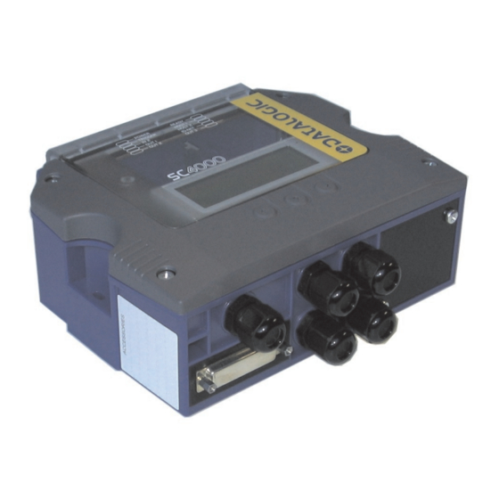
Page 7: General View
GENERAL VIEW SC4000 Figure A Indicator LEDs Display 4x20 Characters 3-Key Keypad Host Interface Module Panel Compression Connectors (5) IP65 protection cover when not using 25-pin Optional Passthrough Device Connector Cover Screws (4) - Page 8 Figure B Power Switch (ON/OFF) Source Chassis Grounding Selector Host 2 RS485 HD Termination Resistance Host 2 Shield Selector Power Source Selector Data Source Port Connector Indicator LEDs Auxiliary Port Connector IP65 Host Interface Module Connector Standard Host Interface Module Connector Spring Clamp Terminal Blocks Mounting Holes (2) Host 1 RS485 HD Termination Resistance Switch...
-
Page 9: Introduction
INTRODUCTION 1 INTRODUCTION 1.1 PRODUCT DESCRIPTION SC4000 is an industrial controller designed for high speed data collection in an ID-NET™ network of Datalogic Automation’s 1D/2D code readers. SC4000 offers high communication performance and connectivity to the most common fieldbus systems by means of a complete range of optional Host Interface modules. - Page 10 ID-NET™ network. Industrial Features SC4000 features IP65 protection class and an operating temperature up to +50 °C (+122 °F). Main Features Some of the main features of this controller are given below: ...
-
Page 11: Accessories
Two Cable Glands Panel 93ACC1847 1.3 SUPPORTED READING DEVICES The following reading devices can be connected as Slave nodes in an ID-NET™ network through a passive CBX100 connection box having SC4000 as the ID-NET™ Master. ID-NET™ Linear Scanners 2D Readers... -
Page 12: Installation
SC4000 REFERENCE MANUAL 2 INSTALLATION 2.1 PACKAGE CONTENTS Verify that the SC4000 and all the parts supplied with the equipment are present and intact when opening the packaging; the list of parts includes: SC4000 ID-NET™ Controller with IP65 25-pin protection cover ... -
Page 13: Overall Dimensions
INSTALLATION 2.2 OVERALL DIMENSIONS The diagram below gives the overall dimensions of the SC4000 and shows the two mounting through-holes. Mounting Holes inch Figure 1 - Overall Dimensions... -
Page 14: Mechanical Installation
Mounting to other surfaces such as concrete walls or metallic panels requires appropriate user-supplied parts (screws, screw anchors, nuts, etc). SC4000 can also be mounted to a DIN rail or a Bosch Frame using the following mounting accessories: BA100 (93ACC1821), BA200 (93ACC1822). -
Page 15: Pinout
PINOUT 3 PINOUT Group Name Function Power Supply Input Voltage + Input Power Power Supply Input Voltage - Earth Protection Earth Ground Power Source – External Trigger External Trigger External Trigger A (polarity insensitive) Input External Trigger B (polarity insensitive) Power Reference –... - Page 16 The input power signals Vdc, GND and Earth as well as the network signals REF, ID+, ID- and Shield; and RTX+, RTX- and SGND are repeated to facilitate system cabling. In this way the power and network busses can enter and exit the SC4000 from different spring clamps but be physically connected together.
-
Page 17: Jumper And Switch Settings
See the relative reading device Reference Manual for details. To power SC4000 from the data source, the power source jumper must be placed in the "power from device" position as indicated in Figure 3. Power from... -
Page 18: Id-Net/Host 1 Shield Jumper Settings
SC4000 REFERENCE MANUAL All Reading Devices (except 6K/8K) to GND Floating to Earth (default) The scanner chassis is internally connected to GND 6K, 8K Family Scanners to Earth (default) Figure 5 – Chassis Grounding 4.1.4 ID-NET/Host 1 Shield Jumper Settings The Network shield (Shield) can be connected to Earth Ground (Earth) either directly or through a filter circuit. -
Page 19: Host 1 Rs485 Hd Termination
JUMPER AND SWITCH SETTINGS 4.2.2 Host 1 RS485 HD Termination Figure 8 – Host 1 RS485 HD Termination Resistance Switch The Host 1 RS485 HD termination resistance switch enables or disables the insertion of the bus termination resistor for RS485 Half Duplex Multidrop applications. In Multiplexer applications the termination resistor must be enabled ONLY on the last device of the chain, the farthest away from the Multiplexer (assuming the Multiplexer is the first device of the chain). -
Page 20: Network Parameter Selectors
Through the SC4000, several types of accessory Host Interface Modules are available to connect the SC4000 ID-NET Master to a Host network as a Slave node of that network. Note: ID-NET™ Slaves (positions 8 and 9) exclude Host network configuration. -
Page 21: Network Address Selection
JUMPER AND SWITCH SETTINGS The Net Type switch setting Software Configuration Controlled Host Interface Network (7) allows the Host network type and Node Address to be set through the software configuration program; the hardware switches are ignored. This position is valid for all the Host network types including Module types that have no hardware switch position (i.e. -
Page 22: Baudrate Selection
4.3.3 Baudrate Selection The Host network baudrates cannot be set through the baudrate switches. In the special case where SC4000 is used as an ID-NET™ network Slave, the ID-NET™ baudrate is selected through the baudrate switch and must match the Master ID-NET™... -
Page 23: Electrical Connections
Flexible stranded wire should be used and must meet the following specifications. All positions: 24 - 16 AWG 0.2 - 1.5 mm² The SC4000 spring clamp connector pinouts are indicated in this chapter and in the Pinout table in chapter 3. -
Page 24: Power Supply
SC4000 REFERENCE MANUAL 5.2 POWER SUPPLY Power is supplied to the SC4000 through the Vdc and GND pins provided on the spring clamp connector. The power switch (see Figure 14) switches the power supply ON or OFF for both the SC4000 and any optional device powered through the 25-pin connector. -
Page 25: Host Interfaces
Interface Modules (Fieldbus and non Fieldbus) with the SC4000. CAUTION The signals relative to the following serial interface types are available on the SC4000 spring clamp terminal blocks. The host serial interface types and their line parameters (baud rate, data bits, etc.) can be defined by the user via Genius™... - Page 26 IDLE IDLE Figure 17 - RS232 Control Signals If the RTS/CTS handshaking protocol is enabled, the SC4000 activates the RTS output to indicate a message is to be transmitted. The receiving unit activates the CTS input to enable the transmission.
- Page 27 The RS485 half-duplex (3 wires + shield) interface is used for polled communication protocols. It can be used for Multidrop connections with a Datalogic MX4000 Multiplexer, exploiting a proprietary protocol based on polled mode called MUX32 protocol, where a master device polls slave devices to collect data.
-
Page 28: Host 2 Interface
SC4000 REFERENCE MANUAL USER INTERFACE RTX485+ SGND RTX485- SC4000 SGND RTX+ RTX- Figure 20 - RS485 Half-duplex Connections This interface is forced by software when the protocol selected is MUX32 communication protocol. In a Multiplexer layout, the Multidrop address must also be set via serial channel by the Genius™... - Page 29 Signal Ground USER INTERFACE SGND RX485+ RX485- TX485+ TX485- SGND SC4000 Figure 22 - RS485 Full-duplex Connections For applications that do not use RX485 signals, do not leave these lines floating but connect them to SGND as shown below. NOTE...
-
Page 30: Id-Net™ Interface
RTX485+ RTX485- SGND RTX+ RTX- SC4000 Figure 24 - RS485 Half-duplex Connections 5.4 ID-NET™ INTERFACE SC4000 features an optoisolated ID-NET high speed interface up to 1 Mbps (500 Kbps default). The following pins are used for connection: Pinout Function Shield Network Cable Shield ID-NET™... -
Page 31: Id-Net™ Cables
1200 m 900 m 700 m * Application dependent, contact your Datalogic Automation representative for details. The default ID-NET™ baudrate is 500 kbps. Lower ID-NET™ baudrates allow longer cable lengths. The baudrate is software configurable by authorized Datalogic Automation personnel only. -
Page 32: Id-Net™ Response Time
ID-NET™ M/S Synchronized layout message length = 50 bytes per node The network must be properly terminated in the first and last device of the network. This is done by setting the ID-NET™ Termination Resistance Switch in the SC4000 to ON. NOTE... - Page 33 ELECTRICAL CONNECTIONS Figure 26 – ID-NET™ Network Connections with isolated power blocks...
- Page 34 SC4000 REFERENCE MANUAL Figure 27 - ID-NET™ Network Connections with Common Power Branch Network...
- Page 35 ELECTRICAL CONNECTIONS Figure 28 – ID-NET™ Network Connections with Common Power Star Network...
-
Page 36: Auxiliary Interface
Signal Ground SGND 1, 4, 6, 7, 8, 9 N.C. USER INTERFACE RX TX Reference Figure 30 - RS232 Auxiliary Interface Connections Do not connect the Aux Interface to the SC4000 spring clamp connectors and the 9-pin connector simultaneously. NOTE... -
Page 37: Data Source Auxiliary Interface
Figure 32 – Data Source Auxiliary Interface Connections 5.7 INPUTS There are two optocoupled polarity insensitive inputs available on the SC4000: Input 1 (External Trigger Input) and Input 2, a generic input. These inputs are typically used when SC4000 is an ID-NET Master in a Synchronized network. -
Page 38: External Trigger Input (Input 1)
Power is available directly to the Input Device, independently from the Power Supply Switch inside the SC4000. CAUTION PH-1 Photocell (PNP) (brown) (black) (blue) Figure 33 – PH-1 External Trigger Using SC4000 Power NPN Photocell Power to Input Photocell Signal Photocell... -
Page 39: Generic Input (Input 2)
Supply Switch inside the SC4000. CAUTION Input Device Power to Input Device Input Input Device Signal Reference PNP Input 2 Using SC4000 Power Input Device Power to Input Input Device Signal Input Device Reference NPN Input 2 Using SC4000 Power... -
Page 40: Outputs
Two optocoupled general purpose outputs are available. The meaning of the two outputs Output 1 and Output 2 can be defined by the user. These outputs are typically used when SC4000 is an ID-NET Master in a Synchronized network. In this case they can be used to signal the data collection results. - Page 41 CAUTION Output Device Power to Output Output device Signal Output device Reference Figure 39 - Open Emitter Output Using SC4000 Power Output Device Power to Output device Output device Reference Output Signal Figure 40 - Open Collector Output Using SC4000 Power...
-
Page 42: Other I/O
Power Reference – Other I/O Input 3B and 4B (common) (p olarity insensitive) I34B Input 3B and 4B (common) (polarity insensitive) put 4A is not managed by SC4000 and is only available to an optionally connected reading device on the 25-pin connector. -
Page 43: Typical Layouts
Host, monitor, etc. The dotted lines in the figure refer to optional hardware configurations. A portable PC can be quickly connected to the SC4000 Auxiliary port through the internal 9- pin connector for SC4000 configuration. An additional optional reading device, such as a Hand-Held reader, can be connected to the 25-pin connector in passthrough towards the Host. -
Page 44: Sc4000 Id-Net™ Multidata Master To Serial Host
SC4000 REFERENCE MANUAL 6.2 SC4000 ID-NET™ MULTIDATA MASTER TO SERIAL HOST ID-NET™ Slave Nodes CBX100 CBX100 CBX100 Power DS2100N Matrix 400™ DS4800 Reader ID-NET™ Interface SC4000 SC4000 ID-NET™ Interface SC4000 Host 1 or Host 2 Serial Interface ... -
Page 45: Sc4000 Id-Net™ Multidata Master To Serial Host And Websentinel Supervisor
TYPICAL LAYOUTS 6.3 SC4000 ID-NET™ MULTIDATA MASTER TO SERIAL HOST AND WEBSENTINEL SUPERVISOR ID-NET™ Slave Nodes CBX100 CBX100 CBX100 Power DS2100N Matrix 400™ DS4800 SC4000 Host WebSentinel Supervisor Reader ID-NET™ Interface Aux Interface for SC4000 Configuration and Genius- ... -
Page 46: Sc4000 Id-Net™ Multidata Master/Fieldbus Slave To Host Fieldbus Master
Communication Settings / Auxiliary Serial <checked> Port / Data Tx Communication Settings / Auxiliary Serial Aligned to the Genius Pc Port / Line Parameters/ (all parameters) configuration 6.4 SC4000 ID-NET™ MULTIDATA MASTER/FIELDBUS SLAVE TO HOST FIELDBUS MASTER ID-NET™ Slave Nodes CBX100 CBX100 CBX100 Power DS2100N Matrix 400™... -
Page 47: Sc4000 Id-Net™ Synchronized Master/Fieldbus Slave To Host Fieldbus Master
Aligned to the Data Source Data Source device Port / Data Pass Through Options / device configuration to the Auxiliary port Termination String 6.5 SC4000 ID-NET™ SYNCHRONIZED MASTER/FIELDBUS SLAVE TO HOST FIELDBUS MASTER ID-NET™ Slave Nodes CBX100 CBX100 CBX100 Power... - Page 48 SC4000 REFERENCE MANUAL Layout ID-NET™ Synchronized Note Master/Fieldbus Slave to Host Fieldbus Master SC4000 (ex: DEVICENET) Parameters Net Type Rotary Switch Fieldbus Interface Board = BM4x0 Address Rotary Switches X100 = 0 Address Range= X10 = 0..6 00..63 = 0..9...
-
Page 49: Indicator Leds
There are ten Indicator LEDs which signal power, communication, and I/O activity and are visible from the SC4000 outside cover. The Power LED is blue when power is correctly applied to the SC4000 and the power switch is turned on. -
Page 50: Display And Keypad
This key selects the value of the data shown on the display Down: This key scrolls functions or programmable data DOWN It is possible to enter the SC4000 menu options by pressing the keypad buttons as described below: Access Menu: press Up and Down arrow keys simultaneously ... -
Page 51: Display Messages
DISPLAY AND KEYPAD 8.3 DISPLAY MESSAGES The messages shown on the SC4000 display are divided into different categories each with its own priority depending on the level of importance. Below is the list of messages, and a few examples providing help to interpret the information reported. -
Page 52: Backup And Restore Procedure
Backup and Restore From SC4000 Display and Keypad To perform Backup: 1. Make sure the Write Protection switch is unlocked (see par. 4.3.4). 2. Press and hold both Up and Down arrow keys simultaneously to enter the SC4000 main menu. 3. Scroll to the Backup] item and select it. -
Page 53: Example Messages
D o n Network State Where: Device OK Device not detected at startup Device detected at startup but not responding to polling Device with diagnostic error Diagnostic Alarm See the References>Diagnostic Error Conditions page in the SC4000 Help On-Line for numeric descriptions.. - Page 54 Four percentage counters display the reading results of the last 100 codes. The bit mask shows which slaves read codes: 0 = not read, 1 = read. Welcome Message Display lines one and two show the SC4000 model and software version. Line three shows the Topology Role: SC4000 Multidata Topology Role...
-
Page 55: Technical Features
Supply Voltage 10 to 30 Vdc* Power Consumption 0.8 - 0.5 A Limited Current Consumption 2.5 A SC4000 + I/O + optional reading device consumption (see related device manual) COMMUNICATION INTERFACES Host 1 Interface RS232/RS485 up to 115.2 Kbit/s Auxiliary RS232 up to 115.2 Kbit/s... - Page 56 SC4000 REFERENCE MANUAL ENVIRONMENTAL FEATURES 0° to 50 C (+32° to 122 °F) Operating Temperature Storage Temperature -20° to 70 C (-4° to 158 °F) Humidity max. 90% non condensing Vibration Resistance 14 mm @ 2 to 10 Hz; 1.5 mm @ 13 to 55 Hz;...
-
Page 57: Index
INDEX Auxiliary Interface, 28 LEDs, 41 Compliance, vi Mechanical Installation, 6 Data Source Auxiliary Interface, 29 Network Bus Termination, 10 Display, 42 Network Parameter Selectors, 12 Electrical Connections, 15 Other I/O, 34 Outputs, 32 Overall Dimensions, 5 General View, vii Package Contents, 4 Pinout, 7 Handling, vi... - Page 58 Bologna - Italy dichiara che declares that the déclare que le bescheinigt, daß das Gerät declare que el SC4000-XXXX ID-NET Controller; e tutti i suoi modelli and all its models et tous ses modèles und seine Modelle y todos sus modelos...
- Page 59 www.automation.datalogic.com...
Need help?
Do you have a question about the SC4000 and is the answer not in the manual?
Questions and answers