Advertisement
Quick Links
Advertisement

Related Manuals for senseca HD53LS Series


Summary of Contents for senseca HD53LS Series
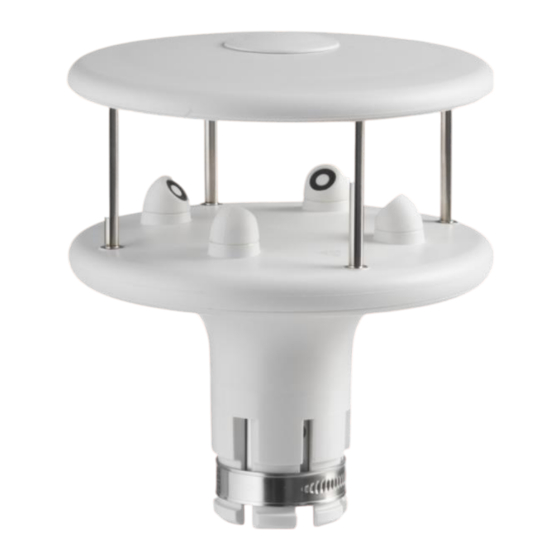
- Page 1 OPERATING MANUAL HD53LS… series Ultrasonic anemometers V1.5...
- Page 2 HD53LS… - Ultrasonic anemometers V1.5 Contents Introduction ......................3 Technical specifications ..................4 Wind speed and direction measurement ............... 5 Installation ......................6 Alignment of the instrument ................7 Electrical Connections..................8 4.2.1 RS232 connection ................9 4.2.2 RS485 connection (only HD53LS.S) ............9 4.2.3 Analog outputs Connection (HD53LS.A and HD53LS.V…) ......
- Page 3 HD53LS… - Ultrasonic anemometers V1.5 Introduction HD53LS… is a series of 2-axis ultrasonic static anemometers for the measurement of: • Wind speed and direction • U-V Cartesian components of wind speed • Wind Gust (only HD53LS.S) The average of wind speed and direction over a period configurable up to 10 minutes is calcu- lated.
- Page 4 HD53LS… - Ultrasonic anemometers V1.5 2 Technical specifications Wind speed Used sensor Ultrasounds Measuring range 0…50 m/s Resolution 0.01 m/s Accuracy ± 0.2 m/s or ± 2%, the greatest (0…35 m/s), ± 3% (> 35 m/s) Wind direction Used sensor Ultrasounds Measuring range 0…359.9°...
- Page 5 HD53LS… - Ultrasonic anemometers V1.5 3 Wind speed and direction measurement Wind speed and direction are determined by measuring the time taken by ultrasonic pulses to cover the distance from the transducer that generates the pulse to the receiving transducer. The instrument uses 2 pairs of transducers oriented along two orthogonal axes.
- Page 6 HD53LS… - Ultrasonic anemometers V1.5 4 Installation To install the instrument, pass the connection cable inside the support mast and connect the 19-pole M23 female connector of the cable to the 19-pole M23 male connector situated at the bottom of the instrument. Ensure connection stability by tightening the connector external nut. Align the instrument to the desired direction (see par.
- Page 7 HD53LS… - Ultrasonic anemometers V1.5 order to prevent faulty indications from the magnetic compass. In case of mobile installations (for example on a boat), consider that the instrument measures the relative (apparent) wind speed with respect to the instrument. To determine the absolute (real) wind speed one should consider the movement velocity of the instrument.
- Page 8 HD53LS… - Ultrasonic anemometers V1.5 Electrical Connections The instrument has 19-pole M23 male connector. Below are the numbering and function of the connector pins and the color correspondence with the wires of the optional CP52.x cable. Reference Male connector (visible side) Connector Connector CP52.x...
- Page 9 HD53LS… - Ultrasonic anemometers V1.5 4.2.1 RS232 connection PC RS232 port Power supply The maximum length of the RS232 connection is typically 15 m. 4.2.2 RS485 connection (only HD53LS.S) Other sensors with RS485 output PLC, datalogger or RS485/USB or RS485/RS232 converter for PC Power supply Multiple sensors can be connected in sequence through a twisted-pair shielded cable for signals...
- Page 10 HD53LS… - Ultrasonic anemometers V1.5 4.2.3 Analog outputs Connection (HD53LS.A and HD53LS.V…) Power supply If the CP52.x cable is used, in which AGND is not available, V- can be used as analog ground (AGND and V- are internally shorted). The anemometer power supply and the load resistance vary according to the type of analog output: Analog output Power supply required...
- Page 11 HD53LS… - Ultrasonic anemometers V1.5 5 Configuration Configuration mode allows to read the instrument general info (firmware version, serial num- ber, …), to read and set the instrument operation parameters. To configure the instrument, a RS232 serial connection to a PC should be performed (see par- agraph 0).
- Page 12 HD53LS… - Ultrasonic anemometers V1.5 General parameters: Command Reply Description CGUVn &| Sets measuring unit of wind speed: ▪ m/s if n=1 ▪ cm/s if n=2 ▪ km/h if n=3 ▪ knot if n=4 ▪ mph if n=5 Default : m/s (n=1) RGUV Reads the wind speed measuring unit set in the instrument...
- Page 13 HD53LS… - Ultrasonic anemometers V1.5 1 : W IND SPEED THRESHOLD VALUE If the wind speed is very low, the determination of the direction can result inaccurate. The in- strument allows setting the threshold value of speed below which the direction value is frozen on the last acquired value.
- Page 14 HD53LS… - Ultrasonic anemometers V1.5 Analog outputs (HD53LS.A and HD53LS.V…): Command Reply Description CAFxnn &| Sets offset and direction of the analog output x (x=1 or 2) to: Standard if nn=00 ▪ [ex. 4…20 mA , 0...1 V , 0...5 V , 0...10 V] ▪...
- Page 15 HD53LS… - Ultrasonic anemometers V1.5 V COMPONENTS By selecting the U and V components, the speed value associated to the initial scale of the two analog outputs is equal to the opposite of the speed value associated to the full scale of the outputs.
- Page 16 HD53LS… - Ultrasonic anemometers V1.5 Parameters for Modbus-RTU mode (only HD53LS.S): Command Reply Description CU5Annn &| Sets Modbus address to nnn The address should range within 1 and 247 Default : 1 RU5A & nnn| Reads the Modbus address setting CU5Bn &| Sets the Baud Rate for Modbus mode to:...
- Page 17 HD53LS… - Ultrasonic anemometers V1.5 6 Modbus-RTU mode (only HD53LS.S) In Modbus-RTU mode, the instrument sends the acquired measurements only if specifically re- quested by the PC, PLC or data logger. Communication parameters should be set in the PC or data logger as follows: •...
- Page 18 HD53LS… - Ultrasonic anemometers V1.5 7 Maintenance Wind speed sensors does not generally require maintenance. In case abnormal measures are detected, verify the cleanliness of the ultrasonic sensors. For cleaning, use a moistened soft cloth. The sensors should be wiped gently: do not brush or twist the sensors.
- Page 19 HD53LS… - Ultrasonic anemometers V1.5 10 Accessories ordering codes CP52… Connecting cable with 19-pole M23 female free connector on one end, open wires on the other. Available lengths: 5 m (CP52.5) and 10 m (CP52.10). RS52 Serial connection cable with built-in USB/RS232 converter. USB connector for the PC and screw terminals on the instrument side.
- Page 20 HD53LS… - Ultrasonic anemometers V1.5 OTES Page 20 of 24...
- Page 21 HD53LS… - Ultrasonic anemometers V1.5 OTES Page 21 of 24...
- Page 22 HD53LS… - Ultrasonic anemometers V1.5 OTES Page 22 of 24...
- Page 23 WARRANTY The manufacturer is required to respond to the "factory warranty" only in those cases provided by Legislative Decree 6 September 2005 - n. 206. Each instrument is sold after rigorous inspections; if any manufacturing defect is found, it is necessary to contact the distributor where the instrument was purchased from.
- Page 24 Senseca Italy S.r.l. Via Marconi, 5 35030 Selvazzano Dentro (PD) ITALY info@senseca.com...
Need help?
Do you have a question about the HD53LS Series and is the answer not in the manual?
Questions and answers