Table of Contents
Advertisement
Quick Links
Advertisement
Table of Contents

Related Manuals for senseca HD2003


Summary of Contents for senseca HD2003
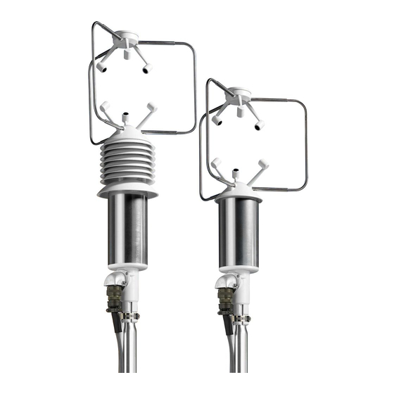
- Page 1 OPERATING MANUAL HD2003 Ultrasonic anemometer V5.0...
-
Page 2: Table Of Contents
HD2003 - Anemometro a ultrasuoni V5.0 Contents Introduction ......................3 Conventions ....................3 Available options ..................... 4 General characteristics ..................4 Operating modes ..................... 5 Specifications ....................6 Installation ......................8 Alignment ....................... 9 Electrical connections ..................9 2.2.1 Power supply and earthing ..............10 2.2.2... -
Page 3: Introduction
HD2003 - Anemometro a ultrasuoni V5.0 1 Introduction Ultrasonic Anemometers allow detecting wind speed and direction. The transit time of the ultrasonic pulse between a pair of opposite sonic transducers, in both directions. From the measurement of tA and tR times, you can trace to the wind speed component in the direction of the two transducers, through the formula: V = D/2 ·... -
Page 4: Available Options
HD2003 - Anemometro a ultrasuoni V5.0 • Symbols The keys of an IBM compatible PC keyboard are identified with a white text on a black background, for example: [Esc] = Esc key, [Enter] = Enter key, = A key One ASCII generic character or several ASCII generic characters can be identified with the symbol: <name>, where name is any expression that gives the title to that character. -
Page 5: Operating Modes
HD2003 - Anemometro a ultrasuoni V5.0 1.4 Operating modes The following operating modes are available: RS232 and RS422 Serial Communication Mode (par. 3.1) A connection over a RS232 or RS422 Serial line is established between a Host Computer and only one anemometer. -
Page 6: Specifications
HD2003 - Anemometro a ultrasuoni V5.0 1.5 Specifications Output quantities Anemometric Wind speed and direction, U-V-W components, wind gust, sound speed, sonic temperature Meteorological Pressure, Temperature, Relative Humidity (only versions with additional sensors) Heading Compass with magnetic azimuth Wind Speed ➢... - Page 7 HD2003 - Anemometro a ultrasuoni V5.0 Additional sensors specifications Pressure Sensor: piezoresistive Range: 600 ÷ 1100 mbar Resolution: 0.1 mbar Accuracy: 0.4 mbar @ 20 °C Temperature Effects: 0.8 mbar between –40 °C and +60 °C Long-term stability: 1 mbar in 6 months @ 20 °C...
-
Page 8: Installation
HD2003 - Anemometro a ultrasuoni V5.0 2 Installation The instrument will be vertically mounted and positioned on “open terrain”, far from turbulences due to near trees or buildings. In the presence of buildings, trees or any other obstruction, the anemometer should be positioned at a height of 10 m above the ground; the distance between the instrument and any obstruction should be at least 10 times the relevant height. -
Page 9: Alignment
HD2003 - Anemometro a ultrasuoni V5.0 2.1 Alignment Orientation A Rotating the anemometer on its vertical axis, it can be fixed in any angular position. The built- in magnetoresistive sensor allows to automatically refer angular measurements to magnetic North, independently of its position. -
Page 10: Power Supply And Earthing
HD2003 - Anemometro a ultrasuoni V5.0 26-pole CP2003/… connector Symbol Description wire color label PWR- Negative Power Supply Brown PWR- (TX+) Negative Power Supply (Tx B RS422) Black PWR+ Positive Power Supply Grey & Brown PWR+ (TX-) Positive Power Supply... -
Page 11: Rs232 Serial Communication Mode
HD2003 - Anemometro a ultrasuoni V5.0 For greater heating effectiveness, it is advisable to use a 30 Vdc power supply, by connecting two pairs of wires, one towards the poles G and K (PWR +) and the other one towards the poles and J and H (PWR-) of the connector. -
Page 12: Rs485 Modbus-Rtu And Multidrop Communication Mode
HD2003 - Anemometro a ultrasuoni V5.0 2.2.4 RS485 Modbus-RTU and Multidrop communication mode This mode can be selected via software (par. 3.1.3). Make a parallel connection between each anemometer of the network and the RS485 port on the PC, (or the RS485/RS232 converter connected to the PC), by using a shielded twisted pair cable. - Page 13 HD2003 - Anemometro a ultrasuoni V5.0 Power Supply ICP DAS I-7024 ® module The same power supply can be used for the anemometer. Power Supply Terminal 12÷30 Vdc ICP DAS I-7024® polo (R) +Vs polo − (B) GND To use the 5 voltage analog outputs of the anemometer together with those of the ICP DAS I- 7024 ®...
-
Page 14: Programming
By consecutively pressing up to 5 characters that are not available on the currently displayed menu page, you get the same effect. Entering Setup, the following main menu is displayed: Anemometer HD2003 Rel. X.Y (X.Y is the anemometer firmware revision) →→ Menu S. Setup L. - Page 15 HD2003 - Anemometro a ultrasuoni V5.0 →→ Setup 1. Baud To select the RS232, RS422, RS485, Modbus-RTU or AoXnd baud rate 2. Gain To set the gain factor for U-V-W, SoW and SUV 3. Threshold To set the minimum threshold for SoW 4.
- Page 16 HD2003 - Anemometro a ultrasuoni V5.0 • Minimum threshold Typed Character: (Threshold) Setting of the minimum threshold displayed. The screen page displays: Sel: 3 [cm/s] [Range= 0 to 500]: It is possible to set a minimum threshold of speed in cm/s, below which SoW is considered equal to zero (= 20 factory default).
- Page 17 HD2003 - Anemometro a ultrasuoni V5.0 • Analog Output Format Typed Character: (Analog Output) Setting of the analog range and the wind speeds range for Analog Outputs and Analog Output Extended (AoXnd) mode. The screen page displays: →→ Analog Output 1.
- Page 18 HD2003 - Anemometro a ultrasuoni V5.0 • Output quantities Typed Character: (Output Quantity) Selection of output quantities in serial RS232, RS422, RS485 Modbus-RTU, RS485 Multidrop, AoXnd and Analog Output mode. The screen page displays: →→ Output Quantity User Esc. Exit...
- Page 19 HD2003 - Anemometro a ultrasuoni V5.0 Analog output mode: The first five quantities in the output data string will be available at the analog outputs, in the order given. For example, setting the output string to st78c59, the last two quantities, i.e. 5...
- Page 20 HD2003 - Anemometro a ultrasuoni V5.0 Example: if there is an anomaly in transducer 4, due to a physical obstruction in the measurement volume, which caused the rejection of 2 raw measurements in a measuring cycle, in the Output Data string the set of three numbers 41 0 2 appears (without anomalies would be 0 0 0).
- Page 21 HD2003 - Anemometro a ultrasuoni V5.0 be active from the next anemometer power on (=RS232 factory default). If ModBusRTU mode is selected, the screen page for the selection of the communication parameters appears: Mode 1. 8N1 2. 8N2 3. 8E1 4.
- Page 22 HD2003 - Anemometro a ultrasuoni V5.0 Sel: R [sec] [Range= 1 to 3600]: You can choose a period in seconds from 1 to 3600, which represents the lapse of time between issuing one Output Data string and the next one. Type the desired period value and then press...
-
Page 23: Logging
HD2003 - Anemometro a ultrasuoni V5.0 3.1.4 Logging By typing from the main menu, the following screen page will display: Here are summarized the values set by the factory calibration, as well as the current configuration of the main parameters that can be managed by the user in Setup. -
Page 24: Multidrop Rs485 And Modbus-Rtu Rs485 Communication Mode
3.2.1 RS485 multidrop settings From the PC, start an RS485 communication program able to: Transmit to the anemometers the commands of HD2003 Communication Protocol (par. 3.2.2). Display and record data and menu pages received from the queried anemometers. -
Page 25: Hd2003 Communication Protocol
HD2003 - Anemometro a ultrasuoni V5.0 3.2.2 HD2003 communication protocol The anemometer can receive four types of commands from the RS485 communication program of the Computer Host or from the HD32MT.1 datalogger: Output Data Command Setup Command ... - Page 26 HD2003 - Anemometro a ultrasuoni V5.0 The Computer Host requires the addressed unit with Identicode = G, to manage the Setup, and transmits in sequence: 1. Break Signal for at least 2ms 2. Command: SGaa • S command (setup) The RS485 communication program after sending the command: S<ID><x><x>...
- Page 27 HD2003 - Anemometro a ultrasuoni V5.0 1. Break Signal for at least 2ms 2. Command: Mfmm It receives the Output Data with 5 measurement values from the instrument with ID=f: IIIIMfI& -5.23 19.18 -1.54 16.00 -1.06 &AAAMfAA<CR> • H and L commands (digital high frequency enabling and disabling) The RS485 communication program after sending the command: H<ID><x><x>...
-
Page 28: Rs485 Modbus-Rtu Settings
HD2003 - Anemometro a ultrasuoni V5.0 3.2.3 RS485 Modbus-RTU settings In Modbus-RTU mode, the anemometer sends the measurements only on a specific request from the PC. This mode is available with the RS485 serial connection. The PC or data logger communication parameters must be set as follows:... - Page 29 HD2003 - Anemometro a ultrasuoni V5.0 A measurement value is stored by the anemometer as an integer value in a 16-bit register, and therefore it always requires two bytes. For the quantities with configurable unit of measurement, the measurement value is expressed in the unit of measurement set in the anemometer, taking into account the number of decimals expected for that quantity, which affects the integer value in the register.
-
Page 30: Analog Output Mode
HD2003 - Anemometro a ultrasuoni V5.0 3.3 Analog output mode As described on page 19, all output quantities can be available as analog outputs, choosing different voltage or current ranges (page 17). Five quantities are available on the anemometer Analog Outputs terminals (OUTVx or OUTmAx). -
Page 31: Anemometer Setting
HD2003 - Anemometro a ultrasuoni V5.0 1. Connect a 12÷30 Vdc Power Supply to the terminals (R)+Vs and (B)GND. 2. Connect DATA+ and DATA- terminals to the correspondents of computer RS485 interface. 3. Connect the terminal INIT* to the terminal (B)GND. -
Page 32: Example Of Analog Output Extended Mode
HD2003 - Anemometro a ultrasuoni V5.0 3.4.3 Example of analog output extended mode The Host computer is used only to configure the ICP DAS I-7024 ® modules and the anemometer. The Analog Outputs of the module, converge for storage in the datalogger HD32MT.1, placed close to the module. -
Page 33: Maintenance
HD2003 - Anemometro a ultrasuoni V5.0 Maintenance Wind speed sensors does not generally require maintenance. In case abnormal measures are detected, verify the cleanliness of the ultrasonic sensors. For cleaning, use a moistened soft cloth. The sensors should be wiped gently: do not brush or twist the sensors. -
Page 34: Accessories Ordering Codes
HD2003 - Anemometro a ultrasuoni V5.0 Accessories ordering codes The anemometer is supplied with 26-pole female free connector (only if the optional cable is not ordered). The cable must be ordered separately. CP2003/… Cable with 26-pole connector on one end, open wires on the other end. Length 5 m (CP2003/5) or 10 m (CP2003/10). - Page 35 GARANZIA Il fabbricante è tenuto a rispondere alla "garanzia di fabbrica" solo nei casi previsti dal Decreto Legislativo 6 settembre 2005, n. 206. Ogni strumento viene venduto dopo rigorosi controlli; se viene riscontrato un qualsiasi difetto di fabbricazione è necessario contattare il distributore presso il quale lo strumento è...
- Page 36 HD2003 - Ultrasonic anemometer V5.0 senseca.com Senseca Italy S.r.l. Via Marconi, 5 35030 Selvazzano Dentro (PD) ITALY info@senseca.com...
Need help?
Do you have a question about the HD2003 and is the answer not in the manual?
Questions and answers