Table of Contents
Advertisement
Quick Links
Advertisement
Table of Contents

Related Manuals for senseca AEOLUS WUS30F


Summary of Contents for senseca AEOLUS WUS30F
- Page 1 OPERATING MANUAL AEOLUS WUS30F Ultrasonic anemometer V0.2...
-
Page 2: Table Of Contents
AEOLUS WUS30F - Ultrasonic anemometer V0.2 Contents Introduction ..................... 3 Technical specifications ................4 Wind speed and direction measurement ........... 6 Installation ....................7 4.1 Alignment of the instrument ..............8 4.2 Tilt angles ..................9 4.3 Electrical connections ................ 10 4.3.1... -
Page 3: Introduction
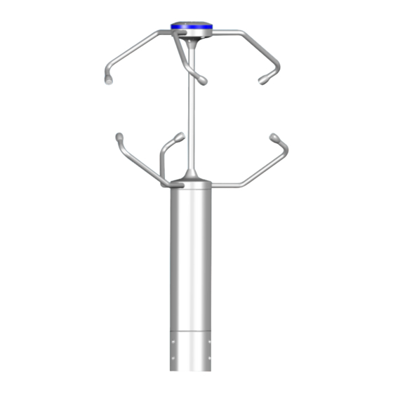
AEOLUS WUS30F - Ultrasonic anemometer V0.2 1 Introduction AEOLUS WUS30F… is a 3-axis ultrasonic static anemometer. In addition to the meas- urement of wind speed and direction, the anemometer also provides the U-V-W Carte- sian components of wind speed and the Wind Gust values. -
Page 4: Technical Specifications
AEOLUS WUS30F - Ultrasonic anemometer V0.2 2 Technical specifications Wind speed Sensor Ultrasounds Measuring range 0…85 m/s Resolution 0.01 m/s Accuracy ± 0.2 m/s or ± 2% of measure, the greatest (0…65 m/s) ± 3% of measure (> 65 m/s) - Page 5 AEOLUS WUS30F - Ultrasonic anemometer V0.2 Measurement interval From 1 to 4 Hz (measurements/s) Wind speed averaging interval Configurable from 1 s to 10 min Wind Gust calculation interval Configurable from 1 s to 10 min Electrical connection 19-pole M23 male connector Operating temperature -40…+70 °C...
-
Page 6: Wind Speed And Direction Measurement
AEOLUS WUS30F - Ultrasonic anemometer V0.2 3 Wind speed and direction measurement Wind speed and direction are determined by measuring the time taken by ultrasonic pulses to cover the distance from the transducer that generates the pulse to the receiv- ing transducer. -
Page 7: Installation
AEOLUS WUS30F - Ultrasonic anemometer V0.2 4 Installation The instrument is supplied with 4 bird spikes, which can be screwed into the holes on the head of the instrument. Be careful not to get hurt by sharp spikes. To install the instrument, pass the connection cable inside the support mast and connect the 19-pole M23 female connector of the cable to the 19-pole M23 male connector situated at the bottom of the instrument. -
Page 8: Alignment Of The Instrument
AEOLUS WUS30F - Ultrasonic anemometer V0.2 In presence of close objects, it is advisable to place the instrument at a height of 10 m. If the instrument is installed on a building, the height of the instrument should be at least 1.5 times the minimum value between the height of the building and the roof... -
Page 9: Tilt Angles
AEOLUS WUS30F - Ultrasonic anemometer V0.2 4.2 Tilt angles For an accurate measurement, the anemometer must be installed in an exactly vertical position. Alignment with respect to the vertical axis can be verified by means of the tilt angles provided by the instrument. -
Page 10: Electrical Connections
AEOLUS WUS30F - Ultrasonic anemometer V0.2 4.3 Electrical connections The instrument has 19-pole M23 male connector. Below are the numbering and function of the connector pins and the color correspondence with the wires of the optional CPM23-19.x cable. Reference Male connector... -
Page 11: Rs232 Connection
AEOLUS WUS30F - Ultrasonic anemometer V0.2 Warning! The metallic housing of the anemometer should be grounded locally, via the support mast. The CPM23-19.x cable shield is connected to the connector shell and then to the metallic housing of the anemometer. Do not connect the gray/red wire (cable shield) to ground, unless it is not possible to ground the anemometer metallic housing locally via the support mast. -
Page 12: Rs422 Connection
AEOLUS WUS30F - Ultrasonic anemometer V0.2 4.3.3 RS422 connection PLC, datalogger or RS485/USB or RS485/RS232 converter for PC Power supply RS422 standard is used for point-to-point connection on long distances, via a shielded cable with two twisted pairs for signals and an additional wire for ground. -
Page 13: Analog Outputs Connection
AEOLUS WUS30F - Ultrasonic anemometer V0.2 4.3.5 Analog outputs connection Power supply The anemometer power supply and the load resistance vary according to the type of analog output: Analog output Power supply required Load resistance 0…20 mA 12…30 Vdc ≤ 500 Ω... -
Page 14: Auxiliary Rs485 Output Connection
AEOLUS WUS30F - Ultrasonic anemometer V0.2 4.3.7 Auxiliary RS485 output connection The auxiliary RS485 output can be used as an alternative to the main serial output for connecting the instrument to the PC, for the configuration of the instrument. The output does not support the operating protocols (NMEA, Modbus-RTU and ASCII proprietary). -
Page 15: Serial Output Protocol
AEOLUS WUS30F - Ultrasonic anemometer V0.2 4.4 Serial output protocol Unless otherwise requested, at the first power up the instrument main serial output starts in configuration mode and waits to receive the commands for setting the operat- ing parameters (see chapter 5) or the connection with the HD52.3D-S application soft- ware. -
Page 16: Configuration
AEOLUS WUS30F - Ultrasonic anemometer V0.2 5 Configuration Configuration mode allows reading the instrument general info (firmware version, serial number, …) and to set the instrument operation mode and operation parameters. The configuration of the instrument can be done: • With the aid of HD52.3D-S application software (see the software online help), downloadable from the website. - Page 17 AEOLUS WUS30F - Ultrasonic anemometer V0.2 Command Reply Description & n| Reads mode set in the instrument. Note 1: after sending the CUMn command, the instrument remains in configuration mode. Power cycle the instrument to activate the set operating mode.
- Page 18 AEOLUS WUS30F - Ultrasonic anemometer V0.2 Command Reply Description CU1Dc…c &| Sets measurements order in the string sent in ASCII proprietary mode. In the sequence c…c, each character identifies a measurement according to the following correspondence: 0 Barometric Pressure 5 ...
- Page 19 AEOLUS WUS30F - Ultrasonic anemometer V0.2 The second digit indicates the type of error: 0 = no errors; 5 = transducer broken, electric interruption, path obstruction; Other = codes reserved to technical service. 2. Second number = heating status: 0 = off, 1 = arms heating is on, 2 = arms heating and transducers heating are both on.
- Page 20 AEOLUS WUS30F - Ultrasonic anemometer V0.2 Parameters for Modbus-RTU mode: Command Reply Description CU5Annn &| Sets Modbus address to nnn. The address should range within 1 and 247. De- fault=1. RU5A & nnn| Reads the Modbus address setting. CU5Bn &| Sets the Baud Rate for Modbus mode to: ▪...
- Page 21 AEOLUS WUS30F - Ultrasonic anemometer V0.2 Units of measurement: Command Reply Description CGUVn &| Sets wind speed unit of measurement: ▪ m/s if n=1 (default) ▪ cm/s if n=2 ▪ km/h if n=3 ▪ knot if n=4 ▪ mph if n=5 RGUV Reads the wind speed unit of measurement.
- Page 22 AEOLUS WUS30F - Ultrasonic anemometer V0.2 Command Reply Description RWaM & n| Reads the method for averaging speed and di- rection. CWgLnnn &| Sets time interval for the calculation of averages in Wind Gust measurement to nnn value. Value should range within 1 and 100 s.
- Page 23 AEOLUS WUS30F - Ultrasonic anemometer V0.2 Vector average: for each measurement, the coordinates of the velocity vector along the measurement axes are calculated and then the average of the coordinates along each axis is calculated. The average intensity and the average direction are those de- termined by the average coordinates.
- Page 24 AEOLUS WUS30F - Ultrasonic anemometer V0.2 6: W UST MEASUREMENT The Wind Gust measurement is determined as follows: • the wind speed averages (according to the method set with the CWgM command, by default vector averages) in a time interval equal to that set with the CWgL command (by default 3 seconds) are calculated continuously;...
- Page 25 AEOLUS WUS30F - Ultrasonic anemometer V0.2 Command Reply Description & n| Reads the association of analog outputs. CAHn &| Associates full scale of wind speed analog output to: ▪ 5 m/s if n=0 ▪ 50 m/s if n=9 ▪ 10 m/s if n=1 ▪...
-
Page 26: Rs232 Ascii Proprietary Mode
AEOLUS WUS30F - Ultrasonic anemometer V0.2 6 RS232 ASCII proprietary mode In RS232 ASCII proprietary mode, the instrument sends automatically the acquired measurements at regular intervals. The interval is factory-set to 1 second and is con- figurable from 1 to 3600 seconds. To change the interval, enter configuration mode and send the command CU2Rnnnn, where nnnn indicates the interval value in seconds (see chapter 5). -
Page 27: Rs485 Ascii Proprietary Mode
AEOLUS WUS30F - Ultrasonic anemometer V0.2 7 RS485 ASCII proprietary mode In RS485 ASCII proprietary mode, the instrument sends the acquired measurements only if requested by the PC. To use this mode, you must connect to a RS485 or RS422 serial port. -
Page 28: Nmea Mode
AEOLUS WUS30F - Ultrasonic anemometer V0.2 8 NMEA mode The instrument is compatible with NMEA 0183 V4.00 protocol. In NMEA mode, the in- strument sends automatically the acquired measurements at regular intervals. The in- terval is factory-set to 1 second and can be configured within 1 and 255 seconds. To change the interval, enter configuration mode and send CU4Rnnn command, where nnn indicates the interval value in seconds (see chapter 5). -
Page 29: Modbus-Rtu Mode
AEOLUS WUS30F - Ultrasonic anemometer V0.2 9 MODBUS-RTU mode By default, the Modbus address is 1 and the communication parameters are 19200, 8E1. The address and the communication parameters can be changed by using the appropriate commands of the configuration mode. -
Page 30: Sdi-12 Mode
AEOLUS WUS30F - Ultrasonic anemometer V0.2 10 SDI-12 mode The instrument is compatible with V1.3 version of the protocol. To use this mode, an SDI-12 serial connection should be performed. The communication parameters are 1200, 7E1. By default, the SDI-12 address is 0 and can be changed by using the appropriate com- mand of the configuration or SDI-12 mode. - Page 31 AEOLUS WUS30F - Ultrasonic anemometer V0.2 Type M (start measurement) commands Command Reply Description Wind speed and direction, barometric pressure atttn<CR><LF> Request to detect the measurements. where: a = address of the instrument (1 character) ttt = number of seconds needed by the instrument to...
- Page 32 AEOLUS WUS30F - Ultrasonic anemometer V0.2 Type R (continuous measurements) commands Command Reply Description aR0! a<WS><WD><NU><CR><LF> Request for measured values. aR1! Parameters not used aR2! a<P><WUV><NU><CR><LF> aR3! a<WSa><WDa><CR><LF> aR4! a<WGS><WGD><CR><LF> aR5! a<WE><WEa><CR><LF> aR6! a<WV><WU><WW><CR><LF> where: a = address of the instrument <WS>...
-
Page 33: Maintenance
AEOLUS WUS30F - Ultrasonic anemometer V0.2 11 Maintenance Wind speed sensors does not generally require maintenance. In case abnormal measures are detected, verify the cleanliness of the ultrasonic sen- sors. For cleaning, use a moistened soft cloth. The sensors should be wiped gently: do not brush or twist the sensors. -
Page 34: Accessories Ordering Codes
AEOLUS WUS30F - Ultrasonic anemometer V0.2 14 Accessories ordering codes The anemometer is supplied with M23 female free connector (only if the optional cable is not ordered), bird spikes and HD52.3D-S PC application software downloadable from the website. The cable must be ordered separately. - Page 35 WARRANTY The manufacturer is required to respond to the "factory warranty" only in those cases provided by Legislative Decree 6 September 2005 - n. 206. Each instrument is sold after rigorous inspections; if any manufacturing defect is found, it is necessary to contact the distributor where the instrument was purchased from.
- Page 36 Senseca Italy S.r.l. Via Marconi, 5 35050 Selvazzano Dentro (PD) ITALY info@senseca.com...
Need help?
Do you have a question about the AEOLUS WUS30F and is the answer not in the manual?
Questions and answers