Advertisement
Quick Links
Advertisement

Related Manuals for Noblelift ANSI FD50


Summary of Contents for Noblelift ANSI FD50
- Page 1 5000-7000 lb Internal Combustion Counterbalance Forklift Truck Operation & Maintenance Manual...
- Page 2 5000-7000 lb Internal Combustion Counterbalance Forklift Truck Operation & Maintenance Manual I. Forklift Truck Main Technical Parameters (Refer to Table 1, Table 2) II. Description about Forklift Truck Main Parts Mechanical Clutch Transmission Case Transmission Speeder Reducer or Power System System Speed Differential Torque...
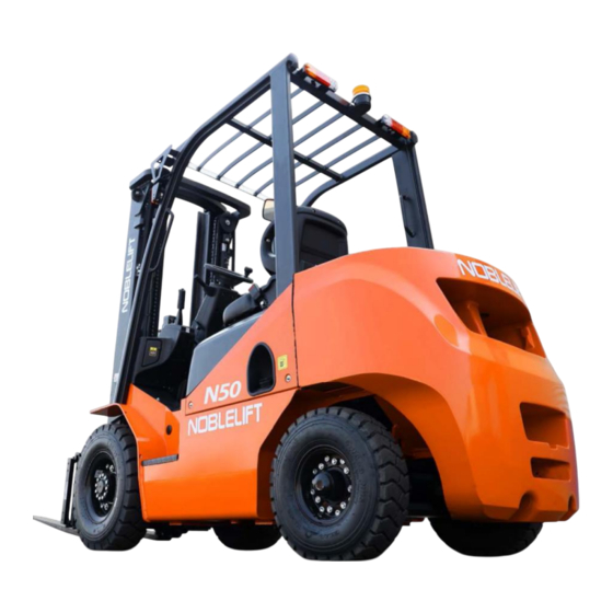
- Page 3 5000-7000 lb Internal Combustion Counterbalance Forklift Truck Operation & Maintenance Manual Outside Drawing of Forklift Truck...
- Page 4 5000-7000 lb Internal Combustion Counterbalance Forklift Truck Operation & Maintenance Manual Main Technical Parameters Table 1 Model FD50 FL50 FGL50 Parameter Rated Load 5000 Load Center Lifting Height Free Lifting Height Mast Tilt Angle Front/Rear 6/10º Lifting 19.5 18.5 18.5 No-Load Speed Full-Load...
- Page 5 5000-7000 lb Internal Combustion Counterbalance Forklift Truck Operation & Maintenance Manual Main Technical Parameters Table 1 Continued Model FD50 FL50 FGL50 Parameter Whole Length L 103.1 (Without Fork) Whole Width W 45.2 Whole Height D 79.1 (Mast Retracted) Whole Height E 158.2 (Mast Extended) Wheelbase F...
- Page 6 5000-7000 lb Internal Combustion Counterbalance Forklift Truck Operation & Maintenance Manual Main Technical Parameters Table 2 Model FL60 FL70 FD60 FD70 FGL60 FGL70 Parameter Rated Load 6000 7000 Load Center Lifting Height Free Lifting Height Mast Tilt Angle Front/Rear 6/10º Lifting Speed No-Load 18.1...
- Page 7 5000-7000 lb Internal Combustion Counterbalance Forklift Truck Operation & Maintenance Manual Main Technical Parameters Table 2 Continued Model FL60 FL70 FD60 FD70 FGL60 FGL70 Parameter Whole Length L 107.7 110.8 (Without Fork) in Whole Width W 47.6 Whole Height D 81.7 84.6 (Mast Retracted) in...
- Page 8 5000-7000 lb Internal Combustion Counterbalance Forklift Truck Operation & Maintenance Manual Table 3 Main Technical Parameters Gasoline-LPG engine Model HMC2.4L Emission Regulation EU STAGE5 / EPA TIER4 4-Stroke, Water-Cooling, Straight-Line, and Type Valve in Head Cylinder: Number of Cylinders – Cylinder 4-Φ88×97 Diameter ×...
- Page 9 5000-7000 lb Internal Combustion Counterbalance Forklift Truck Operation & Maintenance Manual Table 4 Model L4CRTV4(LS) Parameter Type 4Cycle Water-Cooled, Vertical In-Line, Direct Injection, Turbocharged, Electronic controlled Common Rail Fuel System Emission Regulation EU Stage V and EPA Tier4 Number of Cylinders – Cylinder Diameter x 4-88mm×...
- Page 10 5000-7000 lb Internal Combustion Counterbalance Forklift Truck Operation & Maintenance Manual Refer to their respective engine operation and maintenance manuals for the introduction about homemade engines used for 2-3.5t forklift trucks. The power of engine is mainly transmitted to the transmission system from flywheel through clutch or torque converter, and as engine itself carries working oil pump, it is relatively convenient for engine to replace fan belt.
- Page 11 5000-7000 lb Internal Combustion Counterbalance Forklift Truck Operation & Maintenance Manual 12V-60Ah Standard Situation: Ambient Temperature -15℃~+35℃ When used at more than Operating Standard 1000m altitude, the mixed Environment Specification: compensation shall be Regional Altitude Elevation below performed for gasoline 1000m engines in combination with altitudes.
- Page 12 5000-7000 lb Internal Combustion Counterbalance Forklift Truck Operation & Maintenance Manual Engine Authentic Japan-made products to be used o be replaced for every 600 hours or 3 Filter months Authentic Japan-made products to be used To be replaced for every 1200 hours or 6 Filter months Note: The period for replacement in the table indicates general situation (8 hours/day), and...
- Page 13 5000-7000 lb Internal Combustion Counterbalance Forklift Truck Operation & Maintenance Manual Fig 1-1 a) Control the zero adjustment of gear rack, mount the control rack for measurement device onto the end face of control rack for oil injection pump, and align the zero position of control rack for measurement device with the zero position of graduated scale;...
- Page 14 5000-7000 lb Internal Combustion Counterbalance Forklift Truck Operation & Maintenance Manual Fig 1-4). Fig 1-3 Fuel Tank (Diesel Forklift Truck)
- Page 15 5000-7000 lb Internal Combustion Counterbalance Forklift Truck Operation & Maintenance Manual Fig 1-4 Fuel Tank (Gasoline Forklift Truck) 1.4.1 Fuel Tank Fuel tank is an integrated welded structure connected with vehicle chassis into a whole, located on the left side of vehicle chassis. The capacity of fuel tank for 2-2.5t is 52L, 60L for 3-3.5t forklift trucks, and the fuel quantity sensor is fitted on the tank cover of fuel tank to detect the fuel level.
- Page 16 5000-7000 lb Internal Combustion Counterbalance Forklift Truck Operation & Maintenance Manual 1.4.2 Fuel Quantity Sensor K Direction K Direction Full Level Float to Rise to This Place Resistance as 180Ω Fuel position Resistance as (Ω) 图 1-6 汽油滤清器(汽油机特有) Fig 1-6 Gasoline Filter (Specially Available for Gasoline Engines) Float to Drop to This Place...
- Page 17 5000-7000 lb Internal Combustion Counterbalance Forklift Truck Operation & Maintenance Manual d) After reassembly is completed, start engine for gasoline to be filled into the gas cup of filter. Examine whether or not gas leak exists, and Parts 8 and 5 seal rings may be replaced if leak exists.
- Page 18 5000-7000 lb Internal Combustion Counterbalance Forklift Truck Operation & Maintenance Manual the fuel drain pump and start the pump for multiple times. It shall be ensured that no fuel leak exists, engine is started, and warning light is turned off. Firmly tighten the fuel drain plug. b) Air Exhaust Loosen off the air exhaust plug (overflow valve) of oil injection pump, and press the main pump until no air emits.
- Page 19 5000-7000 lb Internal Combustion Counterbalance Forklift Truck Operation & Maintenance Manual 2. Mechanical Transmission Case, Speed Reducer, and Speed Differential Mechanical Transmission Case Type Manual Gear Shift, Slide Synchromesh Gear Number of Gears 2 Gears Respectively for Forward and Backward Forward Gear 1/Gear 2 3.253/1.407 Speed Ratio...
- Page 20 5000-7000 lb Internal Combustion Counterbalance Forklift Truck Operation & Maintenance Manual Fig 2-1 Transmission Device 45. Venthole 34. Bearing Shell 12. Oil Seal 23. Thrust Washer 1. Gear Shift Lever 46. Key 35. Ball Bearing 24. High Gear 13. Ball Bearing 2.
- Page 21 5000-7000 lb Internal Combustion Counterbalance Forklift Truck Operation & Maintenance Manual 2.2 Mechanical Transmission Case The mechanical transmission case is composed of one driving shaft, one output shaft, one main shaft, and one idler shaft (used for reversing gear shift), and one or several gears of different number of teeth are available on each shaft.
- Page 22 5000-7000 lb Internal Combustion Counterbalance Forklift Truck Operation & Maintenance Manual 2.2.6 Synchromesh Gear (Refer to Fig. 2-3.) Synchromesh gear is composed of synchronous taper, synchronous ring, and insert. a) Synchronous Taper: Gear 11 or 13 carries a shaft taper face (synchronous taper) and involute spline, to be respectively combined with the synchronous ring (Part 2) and the engagement sleeve (Part 5) through the friction face and spline gear of this taper face.
- Page 23 5000-7000 lb Internal Combustion Counterbalance Forklift Truck Operation & Maintenance Manual Step 1: (Refer to Fig 2-4) The force through action on the gear shift lever during gear shift, is transmitted onto the engagement sleeve 5 through poking fork, and the engagement sleeve 5 and the insert 7 respectively move a distance X and X .
- Page 24 5000-7000 lb Internal Combustion Counterbalance Forklift Truck Operation & Maintenance Manual Step 4 (Refer to Fig 2-7) After Step 3 is completed, the synchronous engagement sleeve has displaced for a Z distance, so as for the place 15 of the spline gear for synchronous ring (1) to begin to get into contact with the chamfered part of the spline (6) of the engagement sleeve, and at the same time the required friction torque Tc is gradually achieved on the...
- Page 25 5000-7000 lb Internal Combustion Counterbalance Forklift Truck Operation & Maintenance Manual Fig 2-9 Fig 2-10 Power Transmission Driving Shaft 1. Driving Shaft 12. Main Shaft 2. Input Gear 13. Reversing Gear 3. Duplicate Gear 14. Synchronous Taper Output Shaft 4. Duplicate Gear 15. Engagement Sleeve 5.
- Page 26 5000-7000 lb Internal Combustion Counterbalance Forklift Truck Operation & Maintenance Manual Driving Shaft Input Gear Duplicate Gear High-Speed or Low-Speed Gear Synchromesh Gear Main Shaft Synchromesh Gear Reversing Gear of Forward Gear Output Gear Output Shaft to Achieve Power Output Power Transmission Procedure at 1 Forward Gear: 1—2—3—4—11—10—8—9—12—16—15—17—18—5—21...
- Page 27 5000-7000 lb Internal Combustion Counterbalance Forklift Truck Operation & Maintenance Manual 2.4 Speed Differential (Refer to Fig 2-12.) Speed differential is mounted on the front half shell using bearing seat through ball bearings on the two ends, and the front end is connected with axle shell. The shell of speed differential is made into a type of left and right parts, with two half shaft gears and four planetary gears.
- Page 28 5000-7000 lb Internal Combustion Counterbalance Forklift Truck Operation & Maintenance Manual (3) Loosen off the mounting bolts on Case cover (Fig 2-15). Fig 2-15 (4) Perform fast-speed gear shift, from forward to backward, or from backward to forward, for the front end of gear-shift lever to leave the shell of transmission case (Fig 2-16).
- Page 29 5000-7000 lb Internal Combustion Counterbalance Forklift Truck Operation & Maintenance Manual (6) Remove the snap ring on the outer end of rotary rod using calipers, and take it off (Fig 2-18). Fig 2-18 (7) Gently knock at the head of rotary rod (Attention: Not to be heavily opened), and taken off the rotary rod (Fig 2-19).
- Page 30 5000-7000 lb Internal Combustion Counterbalance Forklift Truck Operation & Maintenance Manual replaced with new ones. (3) Generally speaking, respective seal parts and O-rings shall be replaced with new ones. Reassembly procedure is as follows: (1) Mount the spring and the steel ball into the hole of poking fork, set in the gear shift lever, gently knock at it, and have it properly mounted (Fig 2-21).
- Page 31 5000-7000 lb Internal Combustion Counterbalance Forklift Truck Operation & Maintenance Manual (4) The two mounting bolts shall be firstly screwed up using a torque of 28.4-44 N.m (2.9-4.5kg.m), before the lock screw on the end part of shaft arm is tightened up (Fig 2-25).
- Page 32 5000-7000 lb Internal Combustion Counterbalance Forklift Truck Operation & Maintenance Manual (7) Mount the gasket of case cover and the case onto the shell and use the specified torque of 20.6-34.3N.m (2.1-3.5kg.m) to screw down respective bolts (Fig 2-30). Fig 2-30 3.
- Page 33 5000-7000 lb Internal Combustion Counterbalance Forklift Truck Operation & Maintenance Manual 3.2 Main technical parameters Rated output speed of matching engine 2000~2300r/min Rated output power of matching engine 33~45kW Enter the rotation direction (input-oriented) Clockwise Transmission ratio of gearbox: F1=2.195 R1=2.258 Transmission ratio of differential gear: i=7.899...
- Page 34 5000-7000 lb Internal Combustion Counterbalance Forklift Truck Operation & Maintenance Manual 变矩器进油压力测口R Torque converter oil pressure measurement 到散热器去 To the radiator 主油压力测口R Main oil pressure measurement port 加油口 Oil filler Ventilation cap 通气帽 从散热器来 From the radiator 支架 Support 图1 Figure 1 4.
- Page 35 5000-7000 lb Internal Combustion Counterbalance Forklift Truck Operation & Maintenance Manual 1. Conical Nut 2. Wheel Rim 3. Bolt Stud 4. Brake Drum 5. Wheel Hub 6. Brake Cylinder 7. Axle Housing 8. Oil Seal Retainer Ring 9. Oil Seal 10.
- Page 36 5000-7000 lb Internal Combustion Counterbalance Forklift Truck Operation & Maintenance Manual Torque Fig 4-2 5. Steering System Type of Steering System Rear Wheel Steering with Power Steering Power Steering Forklift Truck Tonnage 2t, 2.5t, 3t, 3.5t Cycloid Full Hydraulic Steering Gear BZZ7-125 Φ70 Cylinder Diameter...
- Page 37 5000-7000 lb Internal Combustion Counterbalance Forklift Truck Operation & Maintenance Manual steering wheel. The steering column and the steering wheel are able for forward and backward rotation by 4.5º, to adapt to driver’s different needs. Fully hydraulic steering gear is able to transmit the pressure oil from bypass valve to steering cylinder through pipeline according to the size measurement for the rotation of steering wheel.
- Page 38 5000-7000 lb Internal Combustion Counterbalance Forklift Truck Operation & Maintenance Manual Fig 5-2 Cycloid Fully Hydraulic Steering Gear 1. Limit Post 4. Universal Driving Shaft 7. Rotor 2. Valve Body 5. Leaf Spring 8. Stator 3. Valve Core 6. Connecting Block 9.
- Page 39 5000-7000 lb Internal Combustion Counterbalance Forklift Truck Operation & Maintenance Manual Fig 5-3 Steering Cylinder 1. Piston Body 6. Shaft Sleeve 11. Dust Ring 2. Cylinder Cover 7. O-ring 12. Lining 3. Cylinder Body 8. Shaft Sleeve 13. Block Film 4.
- Page 40 5000-7000 lb Internal Combustion Counterbalance Forklift Truck Operation & Maintenance Manual 5.2 Examination after Reassembly of Steering System (1) Turn the steering wheel leftward and rightward thoroughly to see whether or not left and right force applications are uniform, and whether or not rotation is steady. (2) Examine whether or not oil pressure pipeline is correctly arranged, and whether or not the left and right steering are reversely assembled.
- Page 41 5000-7000 lb Internal Combustion Counterbalance Forklift Truck Operation & Maintenance Manual Wheel Tonnage 1-1.8t 2-2.5t 3-4t Tyre 2× 5.00-8-8 PR 2× 6.00-9-10 PR 2× 6.50-10-10 PR Wheel Rim 3.50D-8 4.00E-9 5.00F-10 Charging Pressure 1000KPa 860KPa 790KPa Total Weight About 105kg About 155kg 6.1 Overview Steering axle is in a type of welded structure of a box cross section (Fig 6-1), and it is...
- Page 42 5000-7000 lb Internal Combustion Counterbalance Forklift Truck Operation & Maintenance Manual Fig 6-1 Steering Axle 1. Oil Seal 7. Tapered Roller Bearing 13. Needle Roller Bearing 19. Link 2. Needle Roller Bearing 8. Lock Nut 14. Oil Seal 20. Pin Shaft 3.
- Page 43 5000-7000 lb Internal Combustion Counterbalance Forklift Truck Operation & Maintenance Manual 6.2 Steering Knuckle and Steering King Pin Steering knuckle is mounted between the upper and lower shaft sleeves on the two ends of steering axle body using steering knuckle king pin, thrust bearing, and gasket. The middle part of king pin is locked on steering knuckle using lock pin, while the two ends of king pin are supported by needle roller bearings pressed on the axle body.
- Page 44 5000-7000 lb Internal Combustion Counterbalance Forklift Truck Operation & Maintenance Manual 7. Brake System Type Front Twin Wheel Brake, Internal Expansion, Hydraulic Pedal Lever Ratio 5.66 Master Cylinder 19.05mm Diameter Wheel Brake 1-1.8t 2-2.5t 3-4t Type Dual Servo Type with Parking Brake Wheel Cylinder 22.22mm 28.58...
- Page 45 5000-7000 lb Internal Combustion Counterbalance Forklift Truck Operation & Maintenance Manual Fig 7-1 Brake Master Cylinder 1. Clevis 5. Stop Steel Wire 9. Main Cup 13. Pump Body 2. Lock Nut 6. Stop Washer 10. Spring 3. Push Rod 7. Auxiliary Cup 11.
- Page 46 5000-7000 lb Internal Combustion Counterbalance Forklift Truck Operation & Maintenance Manual Fig 7-2 1-1.8t Wheel Brake (Left) 1. Wheel Cylinder Piston Top Rod 8. Brake shoe Return Spring 15. Return Spring 22. Washer,cup 2. Shield 9. Spring 16. Ratchet 23. Lever L H Brake 3.
- Page 47 5000-7000 lb Internal Combustion Counterbalance Forklift Truck Operation & Maintenance Manual 1. Spring 2. Rubber Cup 3. Piston 4. Cylinder Body 5. Piston Top Rod 6. Return Spring 7. Top Rod 8. Return Spring 9. Adjusting Lever 10. Auxiliary Brake Shoe 11.
- Page 48 5000-7000 lb Internal Combustion Counterbalance Forklift Truck Operation & Maintenance Manual The brake action in forward movement is as follows (as indicated in Fig 7-5). Through operating brake wheel cylinder, the primary brake shoe and the secondary brake shoe are effected by two forces of equal size but reverse directions, respectively, for brake shoe and brake drum to get into contact with each other, while the primary brake shoe Support Pin...
- Page 49 5000-7000 lb Internal Combustion Counterbalance Forklift Truck Operation & Maintenance Manual 7.5 Manual brake Manual brake adopts a hand-pull flexible shaft body; together with the foot brake, it uses an automatic power shoe brake that acts on the front wheels. Only when the forklift truck has parked, the manual brake can be used.
- Page 50 5000-7000 lb Internal Combustion Counterbalance Forklift Truck Operation & Maintenance Manual Oil Tank Limit Bolt Pedal (Idle Stroke) Brake Master Pump Inching Valve Fig 7-8 Adjustment of Brake Pedal 7.7 Maintenance This section covers brake disassembly, reassembly, and adjustment (with mainly 2t brake described, while the brakes for 3t, 4t and 1-1.8t brakes are similar.
- Page 51 5000-7000 lb Internal Combustion Counterbalance Forklift Truck Operation & Maintenance Manual (2) Remove the return springs for the two brake shoes (Fig 7-10) Fig 7-10 (3) Remove the other three fixed springs (Fig 7-11). Fig 7-11 (4) Detach the primary brake shoe and the secondary brake shoe, and at the same time remove the spring for adjuster.
- Page 52 5000-7000 lb Internal Combustion Counterbalance Forklift Truck Operation & Maintenance Manual (6) Remove the E-shaped retainer ring that fastens the brake cable onto the bottom plate, then remove the mounting bolts on bottom plate, and detach the bottom plate from the axle.
- Page 53 5000-7000 lb Internal Combustion Counterbalance Forklift Truck Operation & Maintenance Manual It is 49.5mm for 1-1.8t forklift truck. (4) Examine the thickness of brake shoe, and replace it if it is found to be excessively worn out. Specified Thickness: 7.2mm (2t) 8.0mm (3t, 4t) 4.87mm (1-1.8t) Minimum Thickness: 2.0mm (2t)
- Page 54 5000-7000 lb Internal Combustion Counterbalance Forklift Truck Operation & Maintenance Manual (8) Measure the free length and installation load of adjuster spring (Fig 7-19 and Fig 7-20). (Refer to Part 12 of Fig 7-3, Part 18 of Fig 7-4, and Part 15 of Fig 7-2.) Free Length: 86mm (2t) 121mm (3t,4t)
- Page 55 5000-7000 lb Internal Combustion Counterbalance Forklift Truck Operation & Maintenance Manual Fig 7-21 2t Forklift Truck Fig 7-22 1-1.8t Forklift Truck and 3t/4t Forklift Trucks (5) Mount the brake cable assembly onto the bottom plate using E-shaped retainer ring. (6) Mount the brake shoe onto the bottom plate using fixing spring, but the bottom part of secondary brake shoe shall be mounted with fixing spring after the washer, cup and the...
- Page 56 5000-7000 lb Internal Combustion Counterbalance Forklift Truck Operation & Maintenance Manual (9) Install adjuster, adjuster spring, top rod, and return spring for top rod (Fig 7-25). Fig 7-25 Pay attention to the following respective items: a) Adjuster Threat Direction and Its Installation Direction (In 2t forklift truck, right-hand threat is used for left brake, while the left-hand thread is used for right brake.
- Page 57 5000-7000 lb Internal Combustion Counterbalance Forklift Truck Operation & Maintenance Manual Fig 7-26 Fig 7-27 c) Examine whether or not the return spring of top rod and the spring for adjuster are damaged, and then examine the rotating status of adjuster gear and whether or not its engaged part is excessively worn out or damaged.
- Page 58 5000-7000 lb Internal Combustion Counterbalance Forklift Truck Operation & Maintenance Manual 7.9 Failure Removal for Wheel Brake Problem Analysis for Cause of Generation Removal Method 1. Oil leak with brake system To be repaired 2. Clearance of brake shoe not properly Adjuster to be adjusted adjusted 3.
- Page 59 5000-7000 lb Internal Combustion Counterbalance Forklift Truck Operation & Maintenance Manual 8. Hydraulic System Forklift Truck 2t-2.5T 3.0T 3.5t Tonnage Equipped Engine SGP1A28.2D2H 9-L093C Yangmar, S4S Model SGP1A28.2D2H 9-R330C Nissan Type Gear Type Driving Driving with Engine Power Output Gear Loaded Displace 72 l/2300r/min...
- Page 60 5000-7000 lb Internal Combustion Counterbalance Forklift Truck Operation & Maintenance Manual Cylinder 2-2.5t: Φ50mm 3t: Φ56mm 3.5t: Φ63mm Inner Diameter -grade Standard Mast at 3m Lifting Height) 1495mm (Varying along with Stroke Type of Mast and Lifting Height) Type Double Act Cylinder 2-2.5t: Φ70mm 3-3.5t: Φ80mm...
- Page 61 5000-7000 lb Internal Combustion Counterbalance Forklift Truck Operation & Maintenance Manual Safety Overflow Valve Lifting Spool Valve Inclined Spool Valve Connected to oil port Bypass Valve M16×1.5 (Connected with Steering Gear) Leading to Oil Tank LS Port Connected with Steering Gear Fig 9-1 Multi-way Valve...
- Page 62 5000-7000 lb Internal Combustion Counterbalance Forklift Truck Operation & Maintenance Manual 8.3.1 Operation of Spool Valve (Taking inclined Spool Valve as example) (1) Neutral Position (Fig 9-2) At this point the High-pressure oil drained Oil Feed One-way Valve from oil pump returns to oil tank through neutral Main Oil Feed Inlet Cylinder interface B position.
- Page 63 5000-7000 lb Internal Combustion Counterbalance Forklift Truck Operation & Maintenance Manual of the entire main valve A moves rightwards, for the pressure oil to be directly connected with low-pressure channel G, for cavity C to be relieved, in order to ensure the stability of system pressure.
- Page 64 5000-7000 lb Internal Combustion Counterbalance Forklift Truck Operation & Maintenance Manual 8.3.3 Action of Inclined Autolock Valve The inclined spool valve is mounted with Tilting Cylinder autolock valve, mainly used to prevent vibration possibly arisen from internal negative pressure of tilting cylinder, and avoid severe aftereffect caused by misoperation.
- Page 65 5000-7000 lb Internal Combustion Counterbalance Forklift Truck Operation & Maintenance Manual Left Lifting Tilting Cylinder Cylinder Right Left Right Safety V alve Safety V alve Cushion V alve Cushion V alve Connected to Lifting Cylinder A Drop Speed Limit Valve Connected to Multi-way Valve P Steering Cylinder...
- Page 66 5000-7000 lb Internal Combustion Counterbalance Forklift Truck Operation & Maintenance Manual 8.5 Lifting Cylinder (Fig 9-8) Two single-acting lifting cylinders are fixed on the rear side of channel steel for the outside mast, and the bottom part of cylinder is fixed on the bracket of lift cylinder on the outside mast using pins and bolts, while the top part of cylinder (namely the top part of piston rod) is connected with active beam.
- Page 67 5000-7000 lb Internal Combustion Counterbalance Forklift Truck Operation & Maintenance Manual There is one shut-off valve on the bottom of lift cylinder, (Refer to Fig 9-9), to prevent cargo from abrupt drop, when high-pressure rubber hose is suddenly cracked. The oil from lift cylinder passes through the spool valve of shut-off valve, and the oil holes around the spool valve allow the two rubber hoes to generate pressure difference.
- Page 68 5000-7000 lb Internal Combustion Counterbalance Forklift Truck Operation & Maintenance Manual Normal Flow Direction Throttle Direction Multi-way Valve Side Lifting Cylinder Side 1. Joint 3. O-Ring 5. Throttle Plate 7. Valve Core 9. Spring 2. Spring 4. Retainer Ring 6. Valve Sleeve 8.
- Page 69 5000-7000 lb Internal Combustion Counterbalance Forklift Truck Operation & Maintenance Manual When tilt spool valve is pushed forward, the high-pressure oil enters from the bottom of cylinder, thus to push forward the piston for mast to tip forward by 6º , and when spool valve is pulled backwards, the high-pressure oil enters from the front end of cylinder body, to push backward the piston, until the mast tips backwards by 12º...
- Page 70 5000-7000 lb Internal Combustion Counterbalance Forklift Truck Operation & Maintenance Manual a) The trace of contact appears on the entire slide Outlet inner surface, and a feeling of obvious coarseness Scratch exists when it is scraped with finger nail. b) Crack appears around the end face, and a severe coarseness is felt when it is scraped with finger nail.
- Page 71 5000-7000 lb Internal Combustion Counterbalance Forklift Truck Operation & Maintenance Manual 8.8.3 Reassembly (Fig 9-17) (1) Clean the disassembled parts. (2) Coat a thin layer of clean grease on the lips of oil seals 8, 9, 10, 11, and 14. (3) Place the pump body 2 and the pump cover 1 on a flat stand, and coat the inner surface of pump body with clean hydraulic oil.
- Page 72 5000-7000 lb Internal Combustion Counterbalance Forklift Truck Operation & Maintenance Manual Before this pump is assembled onto the machine, it is required to examine for a second time whether or not the assembly of the hydraulic pump is correct, and whether or not the rotating direction is correct.
- Page 73 5000-7000 lb Internal Combustion Counterbalance Forklift Truck Operation & Maintenance Manual 1. End Cover 2. Pump Body 3. Bearing 4. Bearing 5. Driving Gear 6. Driven Gear 7. Front End Cover 8. Seal Ring 9. Seal Ring 10. Seal Ring 11. Seal Ring 12 Bolt 13. Lock Washer 14.
- Page 74 5000-7000 lb Internal Combustion Counterbalance Forklift Truck Operation & Maintenance Manual 1. End Cover 2. Pump Body 3. Bearing 4. Bearing 5. Driving Gear 6. Driven Gear 7. Front End Cover 8. Seal Ring 9. Seal Ring 10. Seal Ring 11.
- Page 75 5000-7000 lb Internal Combustion Counterbalance Forklift Truck Operation & Maintenance Manual Fig 9-20 Schematic Drawing of Hydraulic Pipeline (Diesel and Gasoline Forklift Trucks)
- Page 76 5000-7000 lb Internal Combustion Counterbalance Forklift Truck Operation & Maintenance Manual 8.8.5 Failure Removal Problem Possible Cause Removal Method Oil level in oil tank to the low end Oil to be filled to the specified oil level Oil of Oil Pump Staying away Oil suction side pipeline or filter To be cleaned, and oil to be replaced if...
- Page 77 5000-7000 lb Internal Combustion Counterbalance Forklift Truck Operation & Maintenance Manual 9. Lifting System 2-3.5t Type Roller type, “J”-shaped inside mast, “C”-shaped outside mast with free lifting, two-stage telescopic mast End Face of Inside Mast: End Face of Outside Mast: 9.1 Overview Lifting system is a two-stage rolling telescopic mast, with the outside mast typical of a “C”...
- Page 78 5000-7000 lb Internal Combustion Counterbalance Forklift Truck Operation & Maintenance Manual frame move on the portal frame channel steel from up to down smoothly. When the fork rises to the maximum height, one pair of main rollers on left and right on top will extend to the upper edge of the inside mast.
- Page 79 5000-7000 lb Internal Combustion Counterbalance Forklift Truck Operation & Maintenance Manual Starting system is mainly composed of heater plug, key switch, neutral switch, and starter lamp; its function is to start the engine. After the key switch is turned on, the heater plug works, make sure the preheating has completed and the heater plug has stopped working before starting.
- Page 80 5000-7000 lb Internal Combustion Counterbalance Forklift Truck Operation & Maintenance Manual Note: 1. After the engine has stopped, do not place the key switch to ACC gear, so as to avoid the power loss to the battery; 2. When the engine is running, do not start rotate the key switch to ST gear, to prevent damage to the motor;...
- Page 81 5000-7000 lb Internal Combustion Counterbalance Forklift Truck Operation & Maintenance Manual 4. Horn button Horn button is positioned at the center of the steering wheel, and the horn sounds after you press 5. Reversing light and signals Put the gear shift lever to the reverse gear, and the rear light, reversing light and parking sensor buzzer work.
- Page 82 5000-7000 lb Internal Combustion Counterbalance Forklift Truck Operation & Maintenance Manual and operators can quickly determine system failure prior to maintenance. Note: the hourmeter and weighing meter share a digital display zone; when it is powered on, it displays the hour counter and funnel chart; press any key, and it displays the weight value and "kg"...
- Page 83 5000-7000 lb Internal Combustion Counterbalance Forklift Truck Operation & Maintenance Manual Seat light, operator not seated correctly; Neutral indicator light; Engine failure alarm light; : Display the transmission torque converter oil temperature; Fault code display , Off indicates that the engine does not have CAN communication or CAN communication is interrupted;...
- Page 84 5000-7000 lb Internal Combustion Counterbalance Forklift Truck Operation & Maintenance Manual Introduction to electrical box: The electrical box is used to install a chip fuse and relay. The chip fuse is are used to protect the circuits to prevent electrical appliances and wire being burnt due to short circuit. The relay is used to expand the switch capacity, making the small-capacity switch can control high-power electrical appliances.
- Page 85 5000-7000 lb Internal Combustion Counterbalance Forklift Truck Operation & Maintenance Manual Battery: The following matters should be paid attention to when the battery is used: 1) The battery can produce flammable gases, so there is a danger of explosion. Therefore you should avoid short circuit and sparks, and firework is strictly prohibited, to prevent the occurrence of fire or explosion.
- Page 86 5000-7000 lb Internal Combustion Counterbalance Forklift Truck Operation & Maintenance Manual...
- Page 87 5000-7000 lb Internal Combustion Counterbalance Forklift Truck Operation & Maintenance Manual...
- Page 88 5000-7000 lb Internal Combustion Counterbalance Forklift Truck Operation & Maintenance Manual IV. Drive, Operation, and Routine Maintenance of Forklift Truck The forklift drivers and management personnel must bear in mind “Safety First”, and perform safety operation and standard operation according to the forklift truck operation and maintenance manual as well as driver manual.
- Page 89 5000-7000 lb Internal Combustion Counterbalance Forklift Truck Operation & Maintenance Manual (5) Smoothly perform start, turning, driving, brake, and stop. Slow down at turning, on wet or smooth pavements. (6) It is required to place cargo as low as possible, and to keep the mast tilt backwards, when cargo is load for driving.
- Page 90 5000-7000 lb Internal Combustion Counterbalance Forklift Truck Operation & Maintenance Manual (1) When forklift truck is being used, in the case when radiator is overheated or temperature of coolant is excessively high, try as much as possible not to open the radiator cover immediately. Examine the liquid level, in order to find the overheating cause.
- Page 91 5000-7000 lb Internal Combustion Counterbalance Forklift Truck Operation & Maintenance Manual 7. Drawing of Lubricating System...
- Page 92 5000-7000 lb Internal Combustion Counterbalance Forklift Truck Operation & Maintenance Manual...
Need help?
Do you have a question about the ANSI FD50 and is the answer not in the manual?
Questions and answers