Advertisement
Ver.10
Instruction Manual
MG-11
(UV Radiometer)
1. Product Features and Applications
2. Product Specification and Configuration
3. Product Installation
4. Front panel explanation
5. Function explanation
6. Relative Reaction Curves of UV Sensors
7. A/S Request in Case of Product Failure
8. Notes
9. Relay Operation method
10. RS485 Communication protocols
GNF - 722 - 12 (0)
Genicom Co., Ltd.
A4(297×210㎟)
Advertisement
Table of Contents

Related Manuals for GENUV MG-11


Summary of Contents for GENUV MG-11
- Page 1 Ver.10 Instruction Manual MG-11 (UV Radiometer) 1. Product Features and Applications 2. Product Specification and Configuration 3. Product Installation 4. Front panel explanation 5. Function explanation 6. Relative Reaction Curves of UV Sensors 7. A/S Request in Case of Product Failure 8.
- Page 2 Page 1 1. Product Features and Application 1) Features Display is 5 types : Relative Power (RP), Accumulative Time (AT) and Absolute Power (AP) Max power, Dose display (mJ/㎠) Output is 3 types : DC Voltage, DC Current and Relay 2) Applications UV Lamp Monitoring / Water Sterilizer / Air Cleaner/ UV Hardener / UV Irradiator 2.
- Page 3 Page 1 5) Wi-Fi, Bluetooth Module - protocol 802.11 b/g/n (802.11n up to 150 Mbps) Wi-Fi Protocols µ A-MPDU and A-MSDU aggregation and 0.4 guard, interval support Frequency range 2.4 GHz ~2.5 GHz Protocols Bluetooth v4.2 BR/EDR and BLE specification NZIF receiver with –97 dBm sensitivity Bluetooth Radio...
- Page 4 Page 1 - BLE Radio 1. Receiver Parameter Conditions Unit RF transmit power Gain control step RF power control range –12 F = F0 ± 2 MHz –52 Adjacent channel transmit power F = F0 ± 3 MHz –58 F = F0 ± > 3 –60 ∆...
- Page 5 Page 2 3. Production Installation 1) Mounting the Sensor Probe a. Operation temperature of Sensor Probe is -30 ~ 85 ℃ (-22 ~ 185℉) b. UV sensor of Sensor Probe and UV light source should be fixed in set distance to do verticality. Distance is your choice.
-
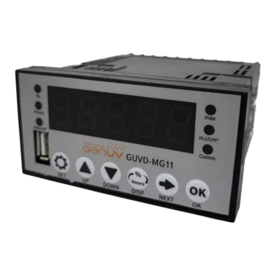
Page 6: Front Panel Explanation
Page 3 4. Front panel explanation Max intensity Relative power(%) Dose display Accumulate time(h) MODBUS Indicator Absolute power(㎽/㎠) LED indicator 5. Function explanation 1) Basic function description - Set button : Resetting RP(%) Power , Reset Max power - Shift button : Reset dose display - Mode button : Switchover the display mode - you can change display mode to press mode button Relative power display... - Page 7 Page 4 ① Setting Relative power - In the Relative power display mode , Press the OK button for 3 seconds. - Press the Set button over 3 second, current optical power will be 100%. ② Reset Accumulate time - In the Accumulate time , Press the OK button for 3 seconds. - Press the Set button over 3 second, Accumulate time value will set to zero.
- Page 8 Page 5 2) Entering setting mode a. Push UP, DOWN button , When switch on the parameters setting plate , C-01 ~ C- 10 would shown. c. Then press the "set“ button ,then will show now time parameters values d. Press the “NEXT” button , enter in the parameters setting mode . e.
- Page 9 Page 5 3) Entering setting mode a. Push UP, DOWN button , When switch on the parameters setting plate , C-01 ~ C- 10 would shown. c. Then press the "set“ button ,then will show now time parameters values d. Press the “NEXT” button , enter in the parameters setting mode . e.
-
Page 10: Function Settings
Page 6 4) Function setting table Function Settings Symbol Item Adjust range Note C – 01 RP Power(%) Alarm 0 ~ 99 C – 02 AT Time Alarm 0 ~ 19999 Hours Please Do not change this Setting of maximum value C –... - Page 11 However, failure which is caused by user’s misuse or carelessness within warrant period or any failure after the warrant period shall be chargeable for it’s A/S. 3) Product inquiry and on-line customer service Tel : +82-42-862-3982, Fax : +82-42-862-2982 E-mail : genuv@geni-uv.com Web site : http://www.geni-uv.com 8. Notes 1) CAUTION TURN ALL POWER OFF.
- Page 12 RS485 AC power AC power Supply Back side of MG-11, Numeric is terminal Number. Fig 6. Connect diagram of MG-05 20 19 18 17 16 15 14 13 12 11 In normal status , the relay will connect #18 and #20 , the Green light will be ON and Red light will be off.
-
Page 13: Modbus Rtu Communication Protocol
Page 9 10. MODBUS RTU Communication protocol 1)ModBus 485 communication protocols: Instruction data are hexadecimal format, write data into the query instructions and directives. Each instruction includes: address code, function code, numerical data length, CRC16 checksum (Check code by the preceding instruction data obtained calculate, specific calculation methods to locate relevant information! Can test the software Automatic calculation of checksum) ======================================================================= 2) Read commands...
Need help?
Do you have a question about the MG-11 and is the answer not in the manual?
Questions and answers