Advertisement
Quick Links
Ver.10
Instruction Manual
MG-05.1
(UV Radiometer)
1. Product Features and Applications
2. Product Specification and Configuration
3. Product Installation
4. Front panel explanation
5. Function explanation
6. Relative Reaction Curves of UV Sensors
7. A/S Request in Case of Product Failure
8. Notes
9. Relay Operation method
GNF - 722 - 12 (0)
Genicom Co., Ltd.
A4(297×210㎟)
Advertisement

Related Manuals for GENUV MG-05.1


Summary of Contents for GENUV MG-05.1
- Page 1 Ver.10 Instruction Manual MG-05.1 (UV Radiometer) 1. Product Features and Applications 2. Product Specification and Configuration 3. Product Installation 4. Front panel explanation 5. Function explanation 6. Relative Reaction Curves of UV Sensors 7. A/S Request in Case of Product Failure 8.
- Page 2 Page 1 1. Product Features and Application 1) Features Display is 5 types : Relative Power (RP), Accumulative Time (AT) and Absolute Power (AP) Max power, Dose display (mJ/㎠) Output is 3 types : DC Voltage, DC Current and Relay 2) Applications UV Lamp Monitoring / Water Sterilizer / Air Cleaner/ UV Hardener / UV Irradiator 2.
- Page 3 Page 2 3. Production Installation 1) Mounting the Sensor Probe a. Operation temperature of Sensor Probe is -30 ~ 85 ℃ (-22 ~ 185℉) b. UV sensor of Sensor Probe and UV light source should be fixed in set distance to do verticality. Distance is your choice.
-
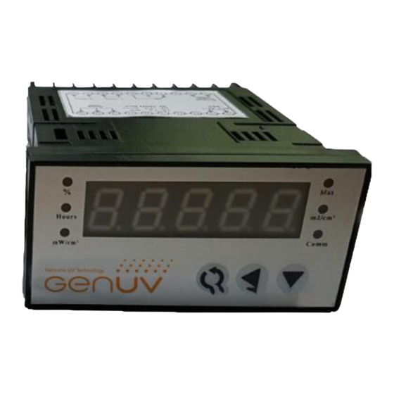
Page 4: Front Panel Explanation
Page 3 4. Front panel explanation Max intensity Relative power(%) Dose display (mJ/㎠) Accumulate time(h) Hours mJ/㎠ RS485 Indicator Absolute power(㎽/㎠) ㎽/㎠ Comm LED indicator Shift Mode 5. Function explanation 1) Basic function description - Set button : Resetting RP(%) Power , Reset Max power - Shift button : Reset dose display - Mode button : Switchover the display mode - you can change display mode to press mode button... - Page 5 Page 4 ① Setting Relative power - In the Relative power display mode , Press the set button for 3 seconds. - Press the Set button over 3 second, current optical power will be 100%. Hours mJ/㎠ Hours mJ/㎠ ㎽/㎠ ㎽/㎠...
- Page 6 Page 5 2) Entering setting mode a. Push Shift + Mode button , When switch on the parameters setting plate , C-01 ~ C- 09 would shown. c. Then press the "set“ button ,then will show now time parameters values d.
-
Page 7: Function Settings
Page 6 3) Function setting table Function Settings Symbol Item Adjust range Note C – 01 RP Power(%) Alarm 0 ~ 99 C – 02 AT Time Alarm 0 ~ 19999 Hours Please Do not change this Setting of maximum value C –... - Page 8 Page 7 6. Relative Reaction Curves of UV Sensors (1) UVV Sensor (2) UVC Sensor Fig. 4 Relative Responsivity Curve of UV Sensor 7. A/S Request in Case of Product Failure 1) Should any failure is found in product, please call the sales company or customer center for A/S. 2) Product warranty period is 1 year from the date of procurement with no charge.
- Page 9 Page 8 9. Relay Operation method 1) Wiring diagram Fig5 Wiring diagram of UV Radiometer 5 a. Connect AC power Terminal #1 and #2 and connect Sensor cable to terminal #18 (Green wire) #19 ( Red wire) #20 (Black wire). Please refer to Fig 6. b.
Need help?
Do you have a question about the MG-05.1 and is the answer not in the manual?
Questions and answers