Download Print this page

Advertisement

Quick Links

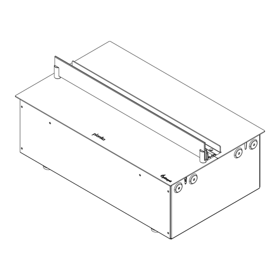
Cool Flame Pro Insert
500,1000, 1500, 2000
EN Installation manual
WARNING / WARNUNG / ADVERTENCIA / AVERTISSEMENT / ATTENZIONE / OSTRZEŻENIE / ВНИМАНИЕ
EN This Manual only applies to the installation of Cool Flame effect 500, 1000, 1500, 2000 Pro Insert only. The operation of the product in casing is included in other manual
DE Dieses Handbuch gilt nur für die Installation von Cool Flame effect 500, 1000, 1500, 2000 Pro Insert. Der Betrieb des Produkts im Gehäuse wird in einem anderen Handbuch beschrieben.
ES Este manual sólo es aplicable a la instalación de Cool Flame effect 500, 1000, 1500, 2000 Pro Insert. El funcionamiento del producto en carcasa se incluye en otro manual
FR Ce manuel s'applique uniquement à l'installation des Cool Flame effect 500, 1000, 1500, 2000 Pro Insert. Le fonctionnement du produit en boîtier fait l'objet d'un autre manuel.
IT Il presente manuale si applica solo all'installazione di Cool Flame effect 500, 1000, 1500, 2000 Pro Insert. Il funzionamento del prodotto in involucro è incluso in altri manuali.
PL Niniejsza instrukcja dotyczy wyłącznie instalacji urządzeń Cool Flame effect 500, 1000, 1500, 2000 Pro Insert. Obsługa produktu w obudowie jest opisana w innej instrukcji.
RU Данное руководство относится только к установке Cool Flame effect 500, 1000, 1500, 2000 Pro Insert. Эксплуатация изделия в корпусе описана в другом руководстве
This product complies with all the required Product Safety, Electromagnetic Compatibility and Environmental Standards. This product is fully compliant with the LVD, EMC, RoHS and Eco Design
Directives.
Copyright Planika Sp. z o.o.
www.planikafires.com
IP0005#11
24.06.2024

Advertisement

loading
Need help?

Need help?

Do you have a question about the Cool Flame 500 Pro Insert and is the answer not in the manual?

Questions and answers

Summary of Contents for Planika Cool Flame 500 Pro Insert

  • Page 1 RU Данное руководство относится только к установке Cool Flame effect 500, 1000, 1500, 2000 Pro Insert. Эксплуатация изделия в корпусе описана в другом руководстве This product complies with all the required Product Safety, Electromagnetic Compatibility and Environmental Standards. This product is fully compliant with the LVD, EMC, RoHS and Eco Design Directives. Copyright Planika Sp. z o.o. www.planikafires.com IP0005#11...
  • Page 2 Table of contents IMPORTANT INFORMATION ............................. 3 GENERAL INFORMATION ............................4 WATER QUALITY & CLEANING ..........................4 INSTALLATION INSTRUCTIONS ..........................5 5. COMMISSIONING/INITIAL PRODUCT START-UP ......................7 6. MULTIPLE PRODUCT INSTALLATION (DAISY CHAINING) ....................7 8. OPERATING THE PRODUCT ............................8 MANUAL &...
  • Page 3 1. IMPORTANT INFORMATION This product is only suitable for well insulated rooms or occasional use. Please read this information guide carefully to be able to safely install, use and maintain your product. Failure to follow these instructions may cause injury and/or damage and may invalidate your guarantee. When using electrical appliances, Pro precautions should always be followed to reduce the risk of fire, electrical shock and injury to persons, including the following: •...
  • Page 4 Swallowing may lead to serious injury in as little as 2 hours or death, due to chemical burns and potential perforation of the oesophagus. If you think batteries might have been swallowed or placed inside any part of the body seek immediate medical attention Examine devices and make sure the battery compartment is correctly secured, e.g.
  • Page 5 Unfiltered water supplied from a well or another unmonitored supply is not recommended. The water tank, sump, sump lid, tank cap and air filters must be cleaned once every week, particularly in hard water areas. This is to remove dirt and prevent build up of limescale which could damage the product.
  • Page 6 WATER CONNECTION It is recommended that you consult a qualified plumber to ensure a safe and secure installation. Two adaptors have been supplied with the product to connect the ¼” blue PVC pipe of the product to mains water (Fig 26.1). Either the white ½ inch or the grey ¾ inch adaptor can be used to connect the product to the mains. For reference, the ¾...
  • Page 7 6. MULTIPLE PRODUCT INSTALLATION (DAISY CHAINING) POWER CONNECTIONS All the products (Cool Flame 500 PRO Insert and 1000, 1500, 2000) can be installed side by side to elongate the Flame effect. When supplying power to multiple products, ensure the maximum wattage of the combined products does not exceed the rated capacity of the MCB (Minature Circuit Breaker) in the circuit.
  • Page 8 MULTIPLE PRODUCT CONTROL Each product has been supplied with its own link wire in order to form a hardwire link between multiple products. Please follow the instructions below to link multiple products together. Identify the ‘master’ product in the installation. It should the product on the left hand side of the installation. Connect the Bluetooth receiver to this product (Fig 15A, 16A, 17A, 18A).
  • Page 9 GETTING THE DESIRED FLAME EFFECT Switch the appliance on by pressing the main switch to the on position and pressing the button. The Flame effects will start after 45seconds. Press the buttons to adjust the Flame effect to your desired level. Please give the Flame effect generator time to react to the changes you make.
  • Page 10 PAIRING THE DEVICE Sign in or create account Verification code Form Starting Sign in or create account by email Click on “send verification code” Fill in the form and continue Click on “lets start” to start or phone and set it in pairing the device PAIRING THE DEVICE Adding the device...
  • Page 11 Device name Guest mode Connect Assign a name for your device and Set guest mode by clicking on “Get Click on “connect” click next Started” or skip by “Maybe later” TURNING ON / OFF DEVICE Starting the device Warming the device Working mode Turning off Click on “ON / OFF button”...
  • Page 12 MENU (IN MANUAL MODE) Main settings Save settings Turn on / off device Set mood Set timer Set schedule Devices list Help Burning effect volume 10. Flame effect 11. Favourite settings 12. Device options...
  • Page 13 Main settings Moods Timer Schedule Access to main information about Choose from favorite or set the Set the time after device will stop Set the schedule of working devices and user. new one working mode or set manual control Volume Devices list Flame effect Device options...
  • Page 14 MY PREFERENCES Main settings My preferences Go to main settings by clicking “main Go to “My preferences to edit profile, reset settings” icon on left upper corner password and check info about app. DEVICE OPTIONS Delete fire Fire info Guest access Product users You can delete the device from Check the device information...
  • Page 15 MOODS Moods Setting colour effect Set the mood from the list or Click on to go to color switch into manual effects NOZZLE INSERTS Nozzle inserts have been supplied and fitted to the nozzle opening. These inserts are used to alter the profile of the Flame effect.
  • Page 16 There are two orange clips holding down the nozzle on the sump; one on the left and one on the right hand side of the nozzle. On the left side, press in the clip with one hand and with the other lift the nozzle out of the clip. Repeat this for the right side (Fig 25).
  • Page 17 12. TROUBLESHOOTING The product has been designed to highlight particular errors by flashing the on board LED lights. The lights will flash a number of times corresponding to the error that is occurring. Please see the table below for the explanation of the errors.
  • Page 18 Japan JP5281417, JP5496291 Brazil BRP10708894 India 4122/KOLNP/2008 New Zealand NZ571900 15. APPENDIX Fig 1 MODEL DIM ‘A’ DIM ‘B’ Cool Flame 500 PRO Insert 518mm 316mm Cool Flame 1000 PRO Insert 1026mm 316mm Cool Flame 1500 PRO Insert 1550mm 316mm...
  • Page 19 Fig 2 Two side open installation Fig 3 MODEL Cool Flame 500 Insert 210cm Cool Flame 1000 Insert 420cm Cool Flame 1500 Insert 630cm Cool Flame 2000 Insert 840cm Fig 4...
  • Page 20 Fig 5 Fig 6 Fig 7 Fig 8 Fig 9 Fig 10 Cool Flame 500 PRO Insert Cool Flame 1000, 1500, 2000 PRO Insert...
  • Page 21 Fig 11 Fig 12 Fig 13...
  • Page 22 Fig 14 Fig 15 Fig 15A Fig 15B Fig 15C Cool Flame 500 Pro Insert Fig 16 Fig 16A Fig 16B Fig 16C Fig 16C Cool Flame 1000 Pro Insert...
  • Page 23 Fig 17 Fig 17B Fig 17A Fig 17C Fig 17C Cool Flame 1500 Pro Insert Fig 18 Fig 18B Fig 18A Fig 18C Fig 18C Cool Flame 2000 Pro Insert Fig 19...
  • Page 24 Fig 20 Cool Flame Insert 500 Pro Cool Flame Insert 1000, 1500, 2000 Fig 21 Fig 22 Fig 23...
  • Page 25 Fig 24 Fig 25 Fig 26 Fig 27 Fig 28 Fig 29...
  • Page 26 Fig 30 Fig 31 Fig 32 Fig 33...
  • Page 27 Fig 34 MODEL Tray lenght Quantity Cool Flame 500 PRO Insert 500mm Cool Flame 1000 PRO Insert 1000mm Cool Flame 1500 PRO Insert 500mm and 1000mm Cool Flame 2000 PRO Insert 1000mm Cool Flame 500 PRO Insert Cool Flame 1500 PRO Insert...