Advertisement
Quick Links
A
G
x 1
SHS Module
L2
Copyright 2017 Planika Sp. z o.o.
INSTALLATION MANUAL
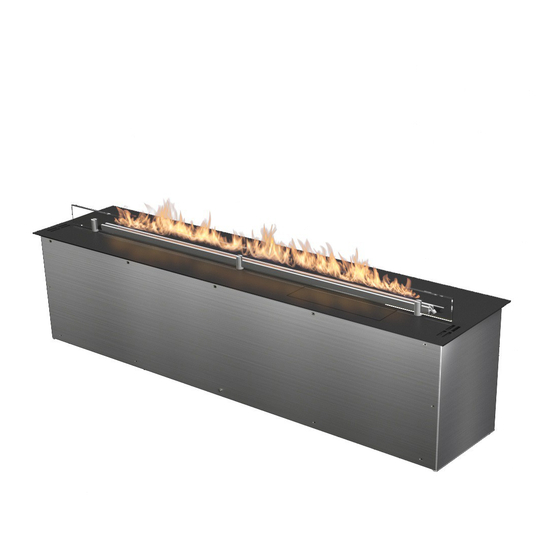
FLA 3#4 XL L=1190 V-S
x 1
H
x 1
MTZ Module
L3
L1
L
www.planikafires.com
B
D
E
x 3
M3x15
I
J
x 1
L2
i1213#00
C
x 2
F
x 3
Connector
K
Automatic
x 1
Service Kit
Fuel Pump
D1
20.02.2017
x 1
x 1
x 1
Device
[mm]
H
232
178
H1
H2
175
H3
3
L
1190
L1
1000
L2
95
D
280
Tank
[mm]
192
H4
L3
954
D1
245
1
Advertisement

Subscribe to Our Youtube Channel
Related Manuals for Planika FLA 3 XL


Summary of Contents for Planika FLA 3 XL
- Page 1 INSTALLATION MANUAL FLA 3#4 XL L=1190 V-S Connector M3x15 Automatic MTZ Module Service Kit SHS Module Fuel Pump Device [mm] 1190 1000 Tank [mm] Copyright 2017 Planika Sp. z o.o. www.planikafires.com i1213#00 20.02.2017...
- Page 2 • It is forbidden to put any products on the burner. • Device must be kept out of reach of children, animals and unauthorized persons. • Do not install the device on a mobile object (eg. caravan, yacht). Copyright 2017 Planika Sp. z o.o. www.planikafires.com i1213#00...
-
Page 3: Installation
Non-flammable materials Non-flammable materials min. 50 mm min. 50 mm min. 1 " min. 1 " min 1000 mm min 1000 mm min 39 " min 39 " Copyright 2017 Planika Sp. z o.o. www.planikafires.com i1213#00 20.02.2017... - Page 4 2 mm (1/16 in) Cable min. 3x1,5mm powered with 230 V, 50 Hz 4 wire cable with ’F’ connector (Optional, needed when the fireplace is meant to be controlled via Smart Home) Copyright 2017 Planika Sp. z o.o. www.planikafires.com i1213#00 20.02.2017...
- Page 5 4 wire cable pinned into the socket at the bottom of the fireplace. (Optional- needed when the fireplace is to be controlled via Smart Home System) Copyright 2017 Planika Sp. z o.o. www.planikafires.com i1213#00 20.02.2017...
- Page 6 Installing the furnace glass shield. Situations where the installation of glass shield protecting the furnace is necessary. Situations in which the montage of the glass slat covering the fireplace is forbidden. Copyright 2017 Planika Sp. z o.o. www.planikafires.com i1213#00 20.02.2017...
- Page 7 - Input turning off the device, signal in form of an 12-24V DC impulse lasting from 100ms to 1s. START - Input turning on the device, signal in form of an 12-24V DC impulse lasting from 100ms to 1s. COM/GND - COM/GND Copyright 2017 Planika Sp. z o.o. www.planikafires.com i1213#00 20.02.2017...
- Page 8 POTENTIAL FREE – enables to control the device without voltage signals. • To select the work mode set the switch on the right side of SHS module in designated position. Work mode selector POTENTIAL / POTENTIAL FREE Copyright 2017 Planika Sp. z o.o. www.planikafires.com i1213#00 20.02.2017...
- Page 9 Connection schemes: Control signals connection scheme Wires from „POTENCIAL” mode fireplace - (12V-24V DC) (12V-24V DC) + Wires from fireplace „POTENCIAL FREE” mode Copyright 2017 Planika Sp. z o.o. www.planikafires.com i1213#00 20.02.2017...
- Page 10 ERROR READY FUEL WORKING Fireplace signals chart (occur in accordance with its status): ERROR FUEL WORKING READY STANDBY ERROR FUEL WORKING READY REFUELING WAIT/COOLING - output signal - no output signal Copyright 2017 Planika Sp. z o.o. www.planikafires.com i1213#00 20.02.2017...
- Page 11 • completely and the display shows NO FUEL, disconnect the power supply and take the device out of the housing. Keep this instruction manual throughout the lifetime of the device. • Copyright 2017 Planika Sp. z o.o. www.planikafires.com i1213#00 20.02.2017...
Need help?
Do you have a question about the FLA 3 XL and is the answer not in the manual?
Questions and answers