Table of Contents
Advertisement
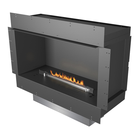
FORMA FIREPLACES
CLEARANCES
AND INSTALLATION
MANUAL
Please read these instructions completely before
installing or operating the Forma Fireplaces
Front
Three-sided
Warnings:
If the information in this manual is not followed exactly, a fire or explosion may result causing property damage, personal injury or loss of life.
Do not fill while operating
FANOLA Bioethanol is the ONLY fuel to be used in this appliance.
Do not use gel, thick and viscous fuels or fuels of improper electric conductivity. The values must be compliant with those of FANOLA®.
Other fuels, such as dehydrated ethanol (i.e. consisting of more than 96.6% by volume ethanol) will cause a device error and loss of the
product warranty. Fuels consisting of 100% by volume ethanol will damage the device. Use only fuels consisting of 86-96.6% ethanol by
volume. FANOLA Bioethanol fuel is the only recommended fuel.
Copyright Planika Sp. z o.o.
Left Corner
Tunnel
Use Planika burners only
www.planikausa.com
Flammable
Keep away from children
I1459#00
Right Corner
Room Divider
08.01.2020
Advertisement
Table of Contents

Related Manuals for Planika FORMA 1000


Summary of Contents for Planika FORMA 1000
- Page 1 Other fuels, such as dehydrated ethanol (i.e. consisting of more than 96.6% by volume ethanol) will cause a device error and loss of the product warranty. Fuels consisting of 100% by volume ethanol will damage the device. Use only fuels consisting of 86-96.6% ethanol by volume. FANOLA Bioethanol fuel is the only recommended fuel. Copyright Planika Sp. z o.o. www.planikausa.com I1459#00...
-
Page 2: Table Of Contents
Table of contents 1. APPLIANCE CLEARANCES ............................3 1.1 Selecting appliance location ..........................3 1.2 Minimum room sizes ............................4 2. APPLIANCE INSTALLATION ............................5 2.1 Framing ................................5 2.2 Definitions ................................ 5 2.3 Before getting started............................5 3. BUILT- IN INSTALLATION ............................7 3.1 Front Installation .............................. -
Page 3: Appliance Clearances
1.1 Selecting appliance location The appliance is zero clearance and has the necessary clearances to combustible frame components already built-in. They are engineered specifically to accept compatible Planika Fire Burners. For indoor use and in housing only. Min. temperature of use is 10°C. -
Page 4: Minimum Room Sizes
1.2 Minimum room sizes Appliance Burner Min. room Size Forma 1000 Front Forma 1000 Left Corner Forma 1000 Right Corner FLA3/FLA3+ 790 60 m Forma 1000 Three-sided Forma 1000 Tunnel Forma 1000 Room Divider Forma 1200 Front Forma 1200 Left Corner... -
Page 5: Appliance Installation
2. APPLIANCE INSTALLATION The appliance must be fully assembled into a fixed secure position before being operated. NOTICE: DO NOT INSTALL DIRECTLY BESIDE OR NEAR WALLPAPER, LAMINATE, VENEER OR ANY SURFACE THAT IS NOT DESIGNED TO WITHSTAND HEAT AND HIGH TEMPERATURES (the heat will impact the material, and in some circumstances the glue used for its application). - Page 6 Firebox Flange extension panel (Peninsula, Double sided) Forma Firebox Stability brackets (2 x in Left/Right Corner and Double Sided 3 x in Peninsula and Bay) 2 x Windscreen (only Peninsula or Double sided) Additional deflector (2 x Additional deflector in Peninsula and Double sided) Installation manual Burner...
-
Page 7: Built- In Installation
Construct the main wall framework with the opening size shown in Table A. Table A. Framework opening size W1 min W2 max D1 max H1 min Appliance Forma 1000 Front 1120 Forma 1200 Front 1320 1020 Forma 1500 Front 1630 1230... - Page 8 3.1 Front Installation Optional SHS, min. 4x0,25 mm AWG 23 230 V, 50 Hz, min. 3x1,5 mm a) Provide electricity connection with 230 V, 50 Hz, min. 3x1,5mm and optional SHS cables with min. 4x0,25 mm2/ AWG 23 inside the cavity. b) Slide the appliance inside the framing cavity.
- Page 9 3.1 Front Installation Option A Option B Standard solution Alternative solution (combustible materials with deflector) (non- combustible materials without deflector) Deflector a) Complete the construction by finishing the wall paneling around a) Complete the construction by finishing the wall paneling around the appliance the appliance with non-flammable materials as on drawing b) Install deflector with screws using the existing mounting holes on...
-
Page 10: Left/Right Corner Installation
Construct the main wall framework with the opening size shown in Table B. Table B Framework opening sizes W1 min W2 max D1 max H1 min Appliance Forma 1000 Left/Right Corner 1120 Forma 1200 Left/Right Corner 1320 1020 Forma 1500 Left/Right Corner 1630 1230... - Page 11 3.2 Left/Right Corner Installation Optional SHS, doprowadЯ pod≥ aczenie min. 4x0,25 mm AWG 23 elektryczne + opcjonalny przewуd do SHS 230 V, 50 Hz, min. 3x1,5 mm wsuс casing w przygotowany otwуr a) Provide electricity connection with 230 V, 50 Hz, min. 3x1,5mm and optional SHS cables with min.
- Page 12 3.2 Left/Right Corner Installation Option A Option B Standard solution Alternative solution (combustible materials with deflector) (non- combustible materials without deflector)) Deflector a) Complete the construction by finishing the wall paneling around a) Complete the construction by finishing the wall paneling around the the appliance appliance with non-flammable materials as on drawing b) Install deflector with screws using the existing mounting holes...
-
Page 13: Three-Sided Installation
Construct the main wall framework with the opening size shown in Table C. Table C Framework opening sizes W1 min W2 max D1 max H1 min Appliance Forma 1000 Three-sided 1098 Forma 1200 Three-sided 1301 1020 Forma 1500 Three-sided 1606 1230... - Page 14 3.3 Three-sided Installation Optional SHS, min. 4x0,25 mm AWG 23 230 V, 50 Hz, min. 3x1,5 mm a) Provide electricity connection with 230 V, 50 Hz, min. 3x1,5mm and optional SHS cables with min. 4x0,25 mm2/ AWG 23 inside the cavity. b) Slide the appliance inside the framing cavity.
- Page 15 3.3 Three-sided Installation Option A Option B Standard solution Alternative solution (combustible materials with deflector) (non- combustible materials without deflector) Deflector a) Complete the construction by finishing the wall paneling around a) Complete the construction by finishing the wall paneling around the appliance the appliance with non-flammable materials as on drawing b) Install deflector with screws using the existing mounting holes on...
-
Page 16: Tunnel Installation
Construct the main wall framework with the opening size shown in Table D. Table D Framework opening sizes W1 min W2 max D1 max H1 min Appliance 1120 Forma 1000 Tunnel 1320 1020 Forma 1200 Tunnel 1630 1230 Forma 1500 Tunnel 1930 1530... - Page 17 3.4 Tunnel Installation Optional SHS, min. 4x0,25 mm AWG 23 230 V, 50 Hz, min. 3x1,5 mm a) Provide electricity connection with 230 V, 50 Hz, min. 3x1,5mm and optional SHS cables with min. 4x0,25 mm2/ AWG 23 inside the cavity. b) Slide the appliance inside the framing cavity.
- Page 18 3.4 Tunnel Installation Option A Option B Standard solution Alternative solution (combustible materials with deflector) (non- combustible materials without deflector)) Deflector a) Complete the construction by finishing the wall paneling around the a) Complete the construction by finishing the wall paneling around appliance the appliance with non-flammable materials as on drawing on b) Install deflector with screws using the existing mounting holes on...
- Page 19 3.4 Tunnel Installation Install the windscreen by inserting the two ends into appropriate slots in the appliance. Repeat the same for the back side windscreen.
-
Page 20: Room Divider Installation
Construct the main wall framework with the opening size shown in Table E. Table E Framework opening sizes W1 min W2 max D1 max H1 min Appliance 1120 Forma 1000 Room Divider 1320 1020 Forma 1200 Room Divider Forma 1500 Room Divider 1630 1230 1930 1530... - Page 21 3.5 Room Divider Installation Optional SHS, min. 4x0,25 mm AWG 23 230 V, 50 Hz, min. 3x1,5 mm a) Provide electricity connection with 230 V, 50 Hz, min. 3x1,5mm and optional SHS cables with min. 4x0,25 mm2/ AWG 23 inside the cavity. b) Slide the appliance inside the framing cavity.
- Page 22 3.5 Room Divider Installation Option A Option B Standard solution Alternative solution (combustible materials with deflector) (non- combustible materials without deflector) Deflector a) Complete the construction by finishing the wall paneling around a) Complete the construction by finishing the wall paneling around the appliance the appliance with non-flammable materials as on drawing on both b) Install deflectors along both sides with screws using the existing...
- Page 23 3.5 Room Divider Installation Install the windscreen by inserting the two ends into appropriate slots in the appliance. Repeat the same for the back side windscreen...
Need help?
Do you have a question about the FORMA 1000 and is the answer not in the manual?
Questions and answers