Table of Contents
Advertisement
Quick Links
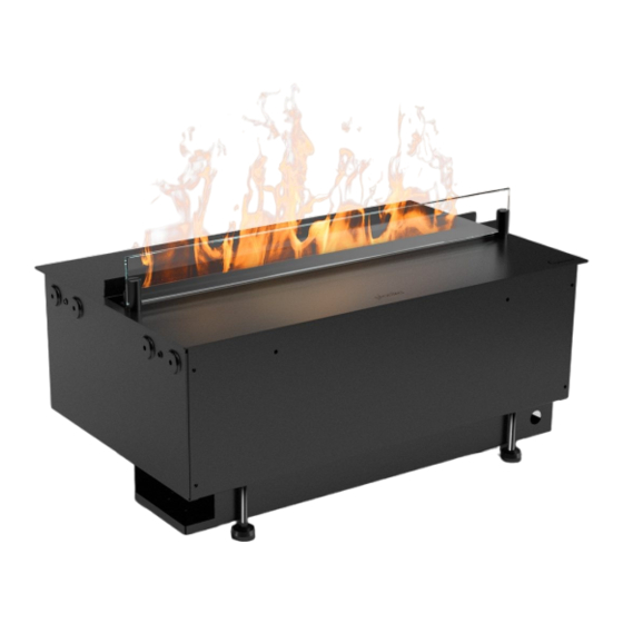
Cool Flame Insert Pro
500,1000
EN Installation manual
WARNING / WARNUNG / ADVERTENCIA / AVERTISSEMENT / ATTENZIONE / OSTRZEŻENIE / ВНИМАНИЕ
EN This Manual only applies to the installation of Cool Flame 500, 1000 Pro Insert only. The operation of the product in casing is included in other manual
DE Dieses Handbuch gilt nur für die Installation von Cool Flame 500, 1000 Pro Insert. Der Betrieb des Produkts im Gehäuse wird in einem anderen Handbuch beschrieben.
ES Este manual sólo es aplicable a la instalación de Cool Flame 500, 1000 Pro Insert. El funcionamiento del producto en carcasa se incluye en otro manual
FR Ce manuel s'applique uniquement à l'installation des Cool Flame 500, 1000 Pro Insert. Le fonctionnement du produit en boîtier fait l'objet d'un autre manuel.
IT Il presente manuale si applica solo all'installazione di Cool Flame 500, 1000 Pro Insert. Il funzionamento del prodotto in involucro è incluso in altri manuali.
PL Niniejsza instrukcja dotyczy wyłącznie instalacji urządzeń Cool Flame 500, 1000 Pro Insert. Obsługa produktu w obudowie jest opisana w innej instrukcji.
RU Данное руководство относится только к установке Cool Flame 500, 1000 Pro Insert. Эксплуатация изделия в корпусе описана в другом руководстве
This product complies with all the required Product Safety, Electromagnetic Compatibility and Environmental Standards. This product is fully compliant with the LVD, EMC, RoHS and Eco Design
Directives.
Copyright Planika Sp. z o.o.
www.planikafires.com
IP0005#08
20.12.2023
Advertisement
Table of Contents

Related Manuals for Planika Cool Flame Insert Pro 500


Summary of Contents for Planika Cool Flame Insert Pro 500
- Page 1 RU Данное руководство относится только к установке Cool Flame 500, 1000 Pro Insert. Эксплуатация изделия в корпусе описана в другом руководстве This product complies with all the required Product Safety, Electromagnetic Compatibility and Environmental Standards. This product is fully compliant with the LVD, EMC, RoHS and Eco Design Directives. Copyright Planika Sp. z o.o. www.planikafires.com IP0005#08...
-
Page 2: Table Of Contents
Table of contents IMPORTANT INFORMATION ............................3 GENERAL INFORMATION ............................4 WATER QUALITY & CLEANING ........................... 4 INSTALLATION INSTRUCTIONS ........................... 5 5. COMMISSIONING/INITIAL PRODUCT START-UP ......................7 6. MULTIPLE PRODUCT INSTALLATION (DAISY CHAINING) ....................7 8. OPERATING THE PRODUCT ............................8 MANUAL &... -
Page 3: Important Information
1. IMPORTANT INFORMATION This product is only suitable for well insulated rooms or occasional use. Please read this information guide carefully to be able to safely install, use and maintain your product. Failure to follow these instructions may cause injury and/or damage and may invalidate your guarantee. When using electrical appliances, Pro precautions should always be followed to reduce the risk of fire, electrical shock and injury to persons, including the following: •... -
Page 4: General Information
Swallowing may lead to serious injury in as little as 2 hours or death, due to chemical burns and potential perforation of the oesophagus. If you think batteries might have been swallowed or placed inside any part of the body seek immediate medical attention Examine devices and make sure the battery compartment is correctly secured, e.g. -
Page 5: Installation Instructions
Unfiltered water supplied from a well or another unmonitored supply is not recommended. The water tank, sump, sump lid, tank cap and air filters must be cleaned once every week, particularly in hard water areas. This is to remove dirt and prevent build up of limescale which could damage the product. - Page 6 WATER CONNECTION It is recommended that you consult a qualified plumber to ensure a safe and secure installation. Two adaptors have been supplied with the product to connect the ¼” blue PVC pipe of the product to mains water (Fig 26.1). Either the white ½ inch or the grey ¾ inch adaptor can be used to connect the product to the mains. For reference, the ¾...
-
Page 7: Commissioning/Initial Product Start-Up
5. COMMISSIONING/INITIAL PRODUCT START-UP CONNECTING THE RECEIVER/TETHERED REMOTE With the fuel bed removed, Connect the Bluetooth receiver connector into the receiver cable socket at the back of the appliance (Fig 9). It is important to ensure that the jack is pushed fully into the socket. Failure to fully insert the connector will prevent the product from functioning correctly. -
Page 8: Operating The Product
MULTIPLE PRODUCT CONTROL Each product has been supplied with its own link wire in order to form a hardwire link between multiple products. Please follow the instructions below to link multiple products together. Identify the ‘master’ product in the installation. It should the product on the left hand side of the installation. Connect the Bluetooth receiver to this product (Fig 15A, 16A). -
Page 9: Manual & Remote Control Options
GETTING THE DESIRED FLAME EFFECT Switch the appliance on by pressing the main switch to the on position and pressing the button. The flames will start after 45seconds. Press the buttons to adjust the flame to your desired level. Please give the flame generator time to react to the changes you make. -
Page 10: Maintenance
FLAME CONNECT APP The fireplace is capable of being controlled using the Flame Connect App for mobile devices. This is available to download to your device from Google Play or Apple App stores. Follow the on screen instructions for set-up. NOTE: The fireplace will not operate using the provided remote control when the app is open on a mobile device. - Page 11 TRANSDUCER The transducer is a consumable item and may need to be replaced through time, depending on its usage. Replacement transducers can be purchased from our your dealer. The transducer is fixed in the sump with a plastic clip. If you need to replace your transducer: Follow the steps 1-5 in the CLEANING - Sump section under ‘Maintenance’...
-
Page 12: Troubleshooting
11. TROUBLESHOOTING The product has been designed to highlight particular errors by flashing the on board LED lights. The lights will flash a number of times corresponding to the error that is occurring. Please see the table below for the explanation of the errors. -
Page 13: Additional Information
12. ADDITIONAL INFORMATION AFTER SALES SERVICE Your product is guaranteed for two years from the date of purchase. Within this period, we undertake to repair or exchange this product free of charge (excluding transducer discs & subject to availability) provided it has been installed and operated in accordance with these instructions. -
Page 14: Appendix
14. APPENDIX Fig 1 MODEL DIM ‘A’ DIM ‘B’ Cool Flame Insert 518mm 316mm 500 Pro Cool Flame Insert 1026mm 316mm 1000 Pro Dim A Dim B Fig 2 Fig 3 Cool Flame Insert 500 Pro... - Page 15 Cool Flame Insert 1000 Pro Fig 4 Fig 5 Fig 6...
- Page 16 Fig 7 Fig 8 Fig 9 Fig 10 Cool Flame Insert 500 Cool Flame Insert 1000 Fig 11...
- Page 17 Fig 12 Fig 13 Fig 14...
- Page 18 Fig 15 Fig 15A Fig 15B Fig 15C Cool Flame Insert 500 Pro Fig 16 Fig 16A Fig 16B Fig 16C Fig 16C Cool Flame Insert 1000 Pro Fig 17...
- Page 19 Fig 18 Cool Flame Insert Cool Flame Insert 1000 Fig 19 Fig 20 Fig 21...
- Page 20 Fig 22 Fig 23 Fig 24 Fig 25 Fig 26...
- Page 21 Fig 27 Fig 28 Fig 29 Fig 30 Fig 31 Cool Flame 500 Insert Cool Flame 1000 Insert...
Need help?
Do you have a question about the Cool Flame Insert Pro 500 and is the answer not in the manual?
Questions and answers