Table of Contents
Advertisement
Quick Links
Advertisement
Table of Contents

Related Manuals for Deye SUN-5K-SG02LP1-AU-AM2


Summary of Contents for Deye SUN-5K-SG02LP1-AU-AM2
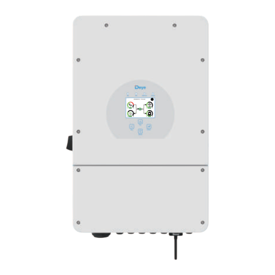
- Page 1 Hybrid Inverter SUN-5K-SG02LP1-AU-AM2 SUN-6K-SG02LP1-AU-AM2 SUN-7.6K-SG02LP1-AU-AM2 SUN-8K-SG02LP1-AU-AM2 SUN-10K-SG02LP1-AU-AM3 05/28/2019 15:34:40 SUN-12K-SG02LP1-AU-AM3 8.30 -3.00 -2.00 3.00 User Manual...
-
Page 2: Table Of Contents
Contents 1. Safety Introductions ………………………………………………… 01 2. Product instructions 02-04 ………………………………………………… 2.1 Product Overview 2.2 Product Size 2.3 Product Features 2.4 Basic System Architecture 2.5 Maintenance of the System 3. Installation 05-21 …………………………………………………………… 3.1 Parts list 3.2 Mounting instructions 3.3 Battery connection 3.4 Grid connection and backup load connection 3.5 PV Connection 3.6 CT Connection... -
Page 3: About This Manual
Documents must be stored carefully and be available at all �mes. Contents may be periodically updated or revised due to product development. The informa�on in this manual is subject to change without no�ce. The latest manual can be acquired via service@deye.com.cn 1. Safety Introduc�ons Safety signs... -
Page 4: Product Overview
2. Product Introduc�ons This is a mul�func�onal inverter, combining func�ons of inverter, solar charger and ba�ery charger to offer uninterrup�ble power support with portable size. Its comprehensive LCD display offers user configurable and easy accessible bu�on opera�on such as ba�ery charging, AC/solar charging, and acceptable input voltage based on different applica�ons. -
Page 5: Product Size
2.2 Product Size Inverter Size - 03 -... -
Page 6: Product Features
2.3 Product Features - Self-consump�on and feed-in to the grid. - Auto restart while AC is recovering. - Programmable supply priority for ba�ery or grid. - Programmable mul�ple opera�on modes: On grid, off grid and UPS. - Configurable ba�ery charging current/voltage based on applica�ons by LCD se�ng. - Configurable AC/Solar/Generator Charger priority by LCD se�ng. -
Page 7: Parts List
3. Installa�on 3.1 Parts List Check the equipment before installa�on. Please make sure nothing is damaged in the package. You should have received the items in the following package: Stainless steel an�-collision Parallel communica�on Hybrid inverter bolt M8×80 cable x1 User manual L-type Hexagon wrench... - Page 8 3.2 Moun�ng instruc�ons Installa�on Precau�on This Hybrid inverter is designed for outdoor use(IP65), Please make sure the installa�on site meets below condi�ons: · Not in direct sunlight · Not in areas where highly flammable materials are stored. · Not in poten�al explosive areas. ·...
- Page 9 ≥500mm ≥500mm For proper air circula�on to dissipate heat, allow a clearance of approx. 50cm to the side and approx. 50cm above and below the unit. And 100cm to the front. Moun�ng the inverter Remember that this inverter is heavy! Please be careful when li�ing out from the package. Choose the recommend drill head(as shown in below pic) to drill 4 holes on the wall, 82-90mm deep.
- Page 10 12 mm ( 0.47 in.) 82~90mm [(3.23 in.)to(3.54 in.)] 3.3 Ba�ery connec�on For safe opera�on and compliance, a separate DC over-current protector or disconnect device is required between the ba�ery and the inverter. In some applica�ons, switching devices may not be required but over-current protectors are s�ll required.
- Page 11 All wiring must be performed by a professional person. Connec�ng the ba�ery with a suitable cable is important for safe and efficient opera�on of the system. To reduce the risk of injury, refer to Chart 3-2 for recommended cables. Please follow below steps to implement ba�ery connec�on: 1.
- Page 12 3.3.2 Func�on port defini�on Inverter 1 2 3 4 5 6 7 8 9 10 ATS_240V BMS 485/CAN DRMs Meter Parallel_A Parallel_B BMS 485/CAN: for ba�ery communica�on. Meter: for energy meter communica�on. Parallel A: Parallel communica�on port 1 Batt Temp Sensor (CAN interface).
-
Page 13: Temp. Sensor
3.3.3 Temperature sensor connec�on for lead-acid ba�ery Temp. sensor - 11 -... - Page 14 3.4 Grid connec�on and backup load connec�on · Before connec�ng to the grid, a separate AC breaker must be installed between the inverter and the grid, and also between the backup load and the inverter.This will ensure the inverter can be securely disconnected during maintenance and fully protected from over current. For the 5/6/7.6/8/10/12kW model, the recommended AC breaker for backup load 5/6kW is 40A, 7.6/8kW is 63A, 10/12kW is 100A.
- Page 15 LOAD GRID GEN PORT GRID GEN PORT LOAD - 13 -...
-
Page 16: Pv Connection
Be sure that AC power source is disconnected before a�emp�ng to wire it to the unit. 3. Then, insert AC output wires according to polari�es indicated on the terminal block and �ghten terminal. Be sure to connect corresponding N wires and PE wires to related terminals as well. 4. -
Page 17: Inverter Model
3.5.1 PV Module Selec�on: When selec�ng proper PV modules, please be sure to consider below parameters: 1) Open circuit Voltage (Voc) of PV modules not exceeds max. PV array open circuit voltage of inverter. 2) Open circuit Voltage (Voc) of PV modules should be higher than min. start voltage. Inverter Model 7.6kW 10kW... -
Page 18: Ct Connection
3.6 CT Connec�on Inverter White wire Black wire Arrow pointing inverter Grid The primary side of the CT needs to be clamped on the If the data read by the CT is wrong, you can try to point Grid live line. the direction of the CT to the grid. - Page 19 Inverter Breaker Meter Parallel_A Parallel_B System connec�on diagram for the Eastron meter Input Output RS 485 230V/2T 230V/2T Grid 1+COM 1+COM RS485A RS485B EASTRON SDM230 Pic 7.1 EASTRON meter Note: Iinverter has built–in leakage current detec�on circuit,If an external RCD is required, a type-A RCD with rated residual current of 300mA or higher is suggested.Otherwise inverter may not work properly - 17 -...
-
Page 20: Earth Connection(Mandatory)
3.7 Earth Connec�on(mandatory) Ground cable shall be connected to ground plate on grid side, this prevents electric shock if the original protec�ve conductor fails. Model Wire Size Cable(mm ) Torque value(max) 5/6kW 8AWG 1.2Nm 7.6/8kW 6AWG 1.2Nm 10/12kW 5AWG 1.2Nm - 18 -... -
Page 21: Wifi Connection
3.8 WIFI Connec�on For the configura�on of Wi-Fi PIug, please refer to illustra�ons of the Wi-Fi PIug. The Wi-Fi PIug is not a standard configura�on, it's op�onal. For WIFI configura�on, please check the manual of "Wi-Fi-Plug configura�on manual". For web monitoring, please visit: h�ps://www.deyecloud.com. For mobile monitoring, please scan the QR code to down load the APP. -
Page 22: Wiring System For Inverter
3.10 Wiring System for Inverter This diagram is an example for grid systems without special requirements on electrical wiring connec�on. Note: The back-up PE line and earthing bar must be grounded properly and effec�vely. DC Breaker Otherwise the back-up func�on may be abnormal when the grid fails. In final installa�on, breaker cer�fied according to AS60947.3 shall be installed with the equipment. -
Page 23: Typical Application Diagram Of Diesel Generator
3.11 Typical applica�on diagram of diesel generator L wire N wire PE wire G-start (7,8): dry contact signal for startup the diesel generator. Inverter Inverter coil relay open contact GS (diesel generator startup signal) Ground Remotely control signal line ① DC Breaker Generator Battery pack... -
Page 24: Operation
4. OPERATION 4.1 Power ON/OFF Once the system has been properly installed and the ba�ery is connected to the inverter, follow the steps below to turn on the inverter: 1. Turn all the breakers of the installa�on on. 2. Turn on the DC switch of the inverter and the power bu�on of ba�ery (If there is one ba�ery installed at the system), no ma�er the order. -
Page 25: Lcd Display Icons
5. LCD Display Icons 5.1 Main Screen The LCD is touchscreen, below screen shows the overall informa�on of the inverter. 05/28/2019 15:34:40 8.30 -3.00 -2.00 3.00 1.The icon in the center of the home screen indicates that the system is Normal opera�on. If it turns into "comm./F01~F64"... -
Page 26: Advanced Function
5.1.1 LCD opera�on flow chart Solar Page Solar Graph Grid Page Grid Graph Inverter Page Main Screen Battery Page BMS Page Load Page Load Graph Battery Setting System Work Mode Grid Setting System Setup Gen Port Use Basic Setting Advanced Function Device info - 24 -... -
Page 27: Solar Power Curve
5.2 Solar Power Curve This is Solar Panel detail page. Solar ① Solar Panel Genera�on. ① ② ② Grid Tie Power: when there’s a string inverter Power: 2923W Grid Tie Power: 2923W AC couple at the grid or load side of hybrid inverter PV1-V: 0V PV2-V: 0V PV3-V: 0V... -
Page 28: Curve Page-Solar & Load & Grid
Li-BMS Mean Voltage:50.34V Charging Voltage :53.2V Batt Total Current:55.00A Discharging Voltage :47.0V Data Mean Temp :23.5C Charging current :50A Total SOC :38% Discharging current :25A Stand-by Dump Energy:57Ah Details SOC: 36% Data Request Force Charge U:50.50V Request Force Charge: It indicates the I:-58.02A BMS requests hybrid inverter to charge Power: -2930W... -
Page 29: System Setup Menu
5.4 System Setup Menu System Setup This is System Setup page. System Work Mode Battery Setting Gen Port Grid Setting Basic Advanced Device Info. Setting Function 5.5 Basic Setup Menu Basic Setting Factory Reset: Reset all parameters of the inverter. Lock out all changes: Enable this menu for se�ng Time Syncs Beep... -
Page 30: Battery Setup Menu
5.6 Ba�ery Setup Menu Ba�ery capacity: it tells Deye hybrid inverter to know Battery Setting your ba�ery bank size. Use Ba� V: Use Ba�ery Voltage for all the se�ngs (V). Batt Mode Use Ba� %: Use Ba�ery SOC for all the se�ngs (%). - Page 31 Generator This page tells generator output voltage, frequency, power. And, how much energy is used from generator. Power: 1392W Today=0.0 KWH Total =2.20 KWH L1: 228V Freq:50.0Hz Battery Setting Lithium Mode: This is BMS protocol.Please reference the document(Approved Ba�ery). Lithium Mode Shutdown 10%: It indicates the inverter will shutdown Batt if the SOC below this value.
-
Page 32: System Work Mode Setup Menu
5.7 System Work Mode Setup Menu System Work Mode Work Mode Selling First(Genera�on limit control): This Mode allows 8000 hybrid inverter to sell back any excess power produced Selling First Max Solar Power by the solar panels to the grid. If �me of use is ac�ve, Work Zero Export To Load Solar Sell... - Page 33 Solar Sell: “Solar sell” is for Zero export to load or Zero export to CT: when this item is ac�ve, the surplus energy can be sold back to grid. When it is ac�ve, PV Power source priority usage is as follows: load consump�on and charge ba�ery and feed into grid.
-
Page 34: Grid Setup Menu
5.8 Grid Setup Menu 5.8.1 Commissioning Procedure If all physical connec�on is checked ok, please follow the steps below. 1.Turn on AC circuit breaker. 2.Turn on DC circuit breaker on PV strings and ba�ery. 3.Turn on circuit breaker on ba�ery pack. 4.Turn on DC switch on the inverter 5.Check the inverter status by inverter indicators and ba�ery status by ba�ery indicators. - Page 35 Default volt-var se�ngs for different regions are shown in the following table: Voltage 220V 240V 207V 258V Australia A Inverter maximum ac�ve 44%supplying 60%absorbing power output level(P) % of S rated Voltage 220V 235V 205V 255V Australia B Inverter maximum ac�ve 30%supplying 40%supplying power output level(P) % of S...
- Page 36 If the Time Syncs Beep Auto Dim engineer does not know the password, please Year Month Basic contact your distributor or Deye. 2019 Hour Minute 24-Hour Factory Reset Lock out all changes 5.8.2 Grid Parameter Check A�er steps above, customers can see firmware version on main page grid parameters in grid...
-
Page 37: Generator Port Use Setup Menu
5.9 Generator Port Use Setup Menu GEN PORT USE Generator input rated power: allowed Max. power from diesel generator. Mode AC couple on grid side GEN connect to grid input: connect the diesel generator to the Generator Input grid input port. AC couple on load side PORT Rated Power... - Page 38 Advanced Function This is for Wind Turbine DC 1 for WindTurbine DC 2 for WindTurbine 16.5 Wind 0.0A 210V 9.0A Set2 110V 1.5A 230V 10.5A 130V 3.0A 250V 12.0A 150V 4.5A 270V 13.5A 170V 6.0A 290V 15.0A 190V 7.5A 310V 16.5A Advanced Function Ex_Meter For CT: when in Three phase system with CHNT...
-
Page 39: Device Info Setup Menu
5.11 Device Info Setup Menu Li-BMS Li-BMS Device Info. This page show Inverter ID, Inverter version and alarm Inverter ID: 1601012001 Flash Charge Charge Volt Volt Curr Curr Temp Temp Energy Energy Fault Fault codes. HMI: Ver0302 MAIN:Ver 0-5213-0717 Volt Volt Curr Curr... - Page 40 Mode IV: AC Couple On-Gen+AC couple AC cable DC cable On-Grid Home Load Grid Solar Backup Load Battery On-Grid Inverter On-Load+AC couple AC cable DC cable On-Grid Inverter Backup Load Solar On-Grid Home Load Battery Grid Smart Load On-Grid+AC couple AC cable DC cable Backup Load...
-
Page 41: Fault Information And Processing
7. Fault informa�on and processing The energy storage inverter is designed according to the grid-connected opera�on standard and meets the safety requirements and electromagne�c compa�bility requirements. Before leaving the factory, the inverter undergoes several rigorous tests to ensure that the inverter can operate reliably. - Page 42 Error code Description Solutions PV isolation resistance is too low 1. Check the connection of PV panels and inverter is firmly and DC insulation impedance correctly; failure 2. Check whether the PE cable of inverter is connected to ground; 3. Seek help from us, if can not go back to normal state. 1.
-
Page 43: Limitation Of Liability
Error code Description Solutions 1. it tells the communication between hybrid inverter and battery BMS disconnected when"BMS_Err-Stop" is active; BMS communication fault 2. if don’t want to see this happen, you can disable "BMS_Err-Stop" item on the LCD; 3. If the fault still exists, please contact us for help. 1. -
Page 44: Datasheet
9. Datasheet SUN-5K- SUN-6K- SUN-7.6K- SUN-8K- SUN-10K- SUN-12K- Model SG02LP1-AU- SG02LP1-AU- SG02LP1-AU- SG02LP1-AU- SG02LP1-AU- SG02LP1-AU- Battery Input Data Ba�ery Type Lead-acid or Lithium-ion Ba�ery Voltage Range(V) 40-60 Max. Charging Current(A) Max. Discharging Current(A) Charging Strategy for Li-Ion Ba�ery Self-adap�on to BMS Number of Ba�ery Input PV String Input Data Max. -
Page 45: Package And Transport Inverter
Power Network Monitoring Island Protec�on Monitoring Earth Fault Detec�on DC Input Switch Overvoltage Load Drop Protec�on Residual Current (RCD) Detec�on An�-islanding Protec�on Yes(Ac�ve Frequency Shi�) Surge Protec�on Level TYPE II(DC), TYPE II(AC) Interface Communica�on Interface WIFI, RS485, CAN PV Connec�on VP-D4 General Data Opera�ng Temperature Range... - Page 46 12. Appendix I Defini�on of RJ45 Port Pin for BMS BMS 485/CAN Pin 1 2 3 4 5 6 7 8 485_B 485_A GND_485 CAN-H CAN-L GND_485 485_A 485_B BMS 485/CAN Port - 44 -...
- Page 47 Meter Port This port is used to connect the energy meter. Note: some hardware versions hybrid inverter don't support conenc�ng the energy meter Meter Pin 1 2 3 4 5 6 7 8 METERB METERA METERB METERA GND_2 METERA METERB DRMs Port DRMs Pin DRM1/5...
- Page 48 RS232 WIFI/RS232 D-GND 12Vdc WIFI/RS232 This RS232 port is used to connect the wifi datalogger - 46 -...
-
Page 49: Appendix
13. Appendix II 1. Split Core Current Transformer (CT) dimension: (mm) 2. Secondary output cable length is 4m. Lead Outside Ver: 2.2, 2024-03-18 - 47 -... - Page 50 Add.: No.26 South YongJiang Road, Daqi, Beilun, NingBo, China. Tel.: +86 (0) 574 8622 8957 Fax.: +86 (0) 574 8622 8852 E-mail: service@deye.com.cn Web.: www.deyeinverter.com...
Need help?
Do you have a question about the SUN-5K-SG02LP1-AU-AM2 and is the answer not in the manual?
Questions and answers