Table of Contents
Advertisement
Quick Links
SPECIFICATIONS
Radio section
Tuning system:
PLL Frequeency synthesizer sys-
tem
Receive range:
AM
FM
Intermediate frequency:
AM
FM
Quieting sensitivity:
AM
FM
Auto tuning stop sensitivity:
AM
FM
FM Separation:
More than 20dB
Clarion Co., Ltd.
50 Kamitoda, Toda-shi, Saitama 335-8511 Japan
Service Dept.: 5-66 Azuma , Kitamoto-shi, Saitama 364-0007 Japan
Tel: +81-48-541-2335 / 2432 FAX: +81-48-541-2703
531kHz to 1629kHz
9 kHz step(PS-2996D)
530kHz to 1710kHz
10 kHz step(PS-2997D)
87.5MHz to 108.0MHz
100 kHz step(PS-2996D)
87.75MHz to 107.9MHz
200 kHz step(PS-2997D)
1st 10.71 +0.2/-0.2MHz
2nd 450 +3/-3kHz
10.7 +0.2/-0.2MHz
Less than 34dBu
(at 20dB S/N)
Less than 15dBu
(at 30dB S/N)
39 +6/-6dBu
24 +6/-6dBu
- 1 -
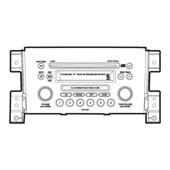
Service Manual
SUZUKI Automobile Genuine
AM/FM TUNER CD COMBI
Black type
PS-2996D-A
Model
(Genuine No.39101-65JQ0-ZCA)
ID No.CLCR05
Brown type
PS-2996D-B
Model
(Genuine No.39101-65JQ0-ZS1)
ID No.CLCR05
PS-2997D-A
Model
(Genuine No.39101-65JN0-ZCA)
ID No.CLCR05
CD section
Disc:
Separation:
S/N ratio:
Distortion:
MP3/WMA section
MP3 sampling rate:
MP3 bit rate:
WMA bit rate:
Logical format:
General
Rated Voltage :
Quiting Output:
Back-up consumption: Less than 5mA
Dimensions(mm):
Weight:
Published by Service Dept.
298-6397-00 Nov.2006
Printed in Japan
12cm Disc
More than 55dB
More than 70dB(JIS-A)
Less than 0.3%(20kHz-LPF)
11.025kHz to 48kHz
8kbps to 320kbps/VBR
48kbps to 192kbps
ISO9660 level 1,2
JOLIET or Romeo
DC 13.2V
More Than 12Wx4 (10% Dist.)
More Than 16Wx4 (Max Output)
248.4(W)x141.5(H)x176.9(D)
approx.1.75kg
PS-2996D-A,B
PS-2997D-A
Advertisement
Table of Contents

Related Manuals for Clarion PS-2996D-A


Summary of Contents for Clarion PS-2996D-A
- Page 1 Clarion Co., Ltd. Published by Service Dept. 50 Kamitoda, Toda-shi, Saitama 335-8511 Japan 298-6397-00 Nov.2006 Service Dept.: 5-66 Azuma , Kitamoto-shi, Saitama 364-0007 Japan Printed in Japan Tel: +81-48-541-2335 / 2432 FAX: +81-48-541-2703 Service Manual SUZUKI Automobile Genuine AM/FM TUNER CD COMBI...
-
Page 2: To Engineers In Charge Of Repair Or Inspection Of Our Products
8. Cautions in handling flexible PWB COMPONENTS Before working with a soldering iron, make sure that the iron tip temperature is around 270 . Take care not to apply the PS-2996D-A,B/PS-2997D-A iron tip repeatedly(more than three times)to the same patterns. Main unit --------------- Also take care not to apply the tip with force. - Page 3 : O : Serial data output to EEP-ROM. SEL 2 ( pin 84 ) pin 49: EEP DI : IN : Serial data input from EEP-ROM. SEL 3 ( pin 85 ) pin 50: NU : - : Not in use. PS-2996D-A,B - 3 - PS-2997D-A...
-
Page 4: Block Diagram
(MPEG audio decode) (WMA decode) 3.3V (CD-DA ESP) 3.3V IC102 Transistor CD DSP IC10 5V >> 3.3V LOGIC TC94A15F FLASH ROM SN74LVC139 MBM29DL800BA (Digital servo) (8Mbit) (DF/DAC) Regulator 3.3V >> 1.6V LOGIC SN74HCT08 ACC8V J3 20pin ACC5V PS-2996D-A,B - 4 - PS-2997D-A... -
Page 5: Exploded View Parts List
EXPLODED VIEW/PARTS LIST Escutcheon section Clamping torque value of a screw is 0.2 +0.04/-0.04 Newton meter. Note)Some parts depend on each model.The model name is specified in the descripion . (6D-A;PS-2996D-A, 6D-B;PS-2996D-B,7D-A;PS-2997D-A ) PART NO. DESCRIPTION Q'TY PART NO. DESCRIPTION... - Page 6 Main section Clamping torque value of a screw is 0.4 +0.08/-0.08 Newton meter. Note)Some parts depend on each model.The model name is specified in the descripion . (6D-A;PS-2996D-A, 6D-B;PS-2996D-B,7D-A;PS-2997D-A ) PART NO. DESCRIPTION Q'TY PART NO. DESCRIPTION Q'TY 076-0662-74 PLUG(26P)
- Page 7 CD mechanism section:(929-5005-80) PS-2996D-A,B - 7 - PS-2997D-A...
- Page 8 620-1023-23 CLAMPER PLATE 621-0718-21 ROLLER GUIDE 620-1752-20 SENSOR ARM 621-0719-20 ROLLER GEAR 621-0728-20 STOPPER LINK 621-0720-20 ROLLER GEAR C 621-1752-20 DISC STOPPER 621-0721-20 ROLLER GEAR D 621-1753-20 CLAMPER RING 621-1719-20 IDLE CASE 750-3471-20 SENSOR SPRING PS-2996D-A,B - 8 - PS-2997D-A...
-
Page 9: Electrical Parts List
Switch PWB section (B1) One of those parts is used in the set. Note)Some parts depend on each model.The model name is specified in the descripion . (2996D ;PS-2996D-A, -B/ 2997D ;PS-2997D-A ) REF No. PART No. DESCRIPTION REF No. PART No. - Page 10 119-1021-15 1/10W 1k ohm SUP101 060-0122-20 DSP-141N-SOOB R111 119-0000-05 1/10W 0 ohm JW R535 119-1031-15 1/10W 10k ohm TH711 002-0318-01 1206L035YRT R121 119-0000-05 1/10W 0 ohm JW R536 119-2221-15 1/10W 2.2k ohm TM101 073-0762-90 TERMINAL PS-2996D-A,B - 10 - PS-2997D-A...
- Page 11 Sensor PWB(B4) section REF No. PART No. DESCRIPTION REF No. PART No. DESCRIPTION REF No. PART No. DESCRIPTION 001-7058-90 AN1105W-RR 060-4015-90 PS1192H 013-7413-50 LIMIT 001-7058-90 AN1105W-RR 060-4015-90 PS1192H 039-2675-00 PWB(WITHOUT 074-1138-60 10P 013-7414-50 CHUCKING COMPONENTS) PS-2996D-A,B - 11 - PS-2997D-A...
-
Page 12: Circuit Diagram
A1298 R122 C124 3.3K 1 50V LN C123 1000p 2.5V SD/ST PLL-CE 10 11 12 PLL-DO X121 7.2MHz PLL-CL To Main PWB 2/4 IC121 Page 13 LC72146M PLL-DI C160 AM/FM:0.2V R127 U-GND(1) SYS+5V(1) R128 L121 PS-2996D-A,B - 12 - PS-2997D-A... - Page 13 Page 15 WMA-SCK SYS+5V(2) R554 5.2V SYS+5V(5) U-GND(2) B/U(4) R549 ACC(4) 330K ILL(+) ILL(-) To Main PWB 1/4 IC502 Page 12 NJM2103M SD/ST Q505 R555 C4116 PLL-CE 5.6K PLL-DO PLL-CL Q504 C4116 PLL-DI SYS+5V(1) U-GND(1) PS-2996D-A,B - 13 - PS-2997D-A...
- Page 14 1.2K AMP-MUTE Page 15 TEL/AUX-L Page 13 AMP-ON Q391 TEL/AUX-L AMP-ON TEL/AUX-R BEEP DTC114EUA AUX-L C360 R359 TEL/AUX-R BEEP TEL/AUX-G 10 16V 10K F Q392 C4116 TEL/AUX-G R355 10K F TEL/AUX-L C354 R360 10K F PS-2996D-A,B - 14 - PS-2997D-A...
- Page 15 AUX-IN R-CH (+) R903 0 L(+) R-CH INPUT(-) R726 L(-) To Main PWB 3/4 L-CH(+) SYS-ACC Page 14 L(+) TEL/AUX-L 10 BUS (-) J701 TEL/AUX-L 074-1194-00 11 L-CH INPUT(-) R905 TEL/AUX-R TEL/AUX-R ILLUMINATION (+) TEL/AUX-G N.C. TEL/AUX-G PS-2996D-A,B - 15 - PS-2997D-A...
- Page 16 J231 COMPONENT SIDE: Parts on the component side seen from the component side are indicated. Flat wire Main PWB (B2) (816-4030-50) To J100 of Switch PWB Page 19 To J3 of CD Mechnism Page 22 PS-2996D-A,B - 16 - PS-2997D-A...
- Page 17 ILLUMINATION (+) N.C. J801 SOLDER SIDE CAT-TP The parts of a dotted line express the parts on a component side. Caution: SOLDER SIDE:Parts on the solder side seen from the solder side are indicated. J231 P501 PS-2996D-A,B - 17 - PS-2997D-A...
- Page 18 COMMK C901 C902 DISP/PAGE DOWN C903 C904 VLCD2 10 11 12 13 14 15 16 17 18 19 20 21 22 23 24 FM/AM L901 CD/AUX R921 180K R922 180K R916 R923 180K R924 180K PS-2996D-A,B - 18 - PS-2997D-A...
- Page 19 DOWN SCAN FM/AM CD/AUX Caution: COMPONENT SIDE: Parts on the component side seen from the component side are indicated. SOLDER SIDE: Parts on the solder side seen from the solder side are indicated. DISC/PAGE MUTE PS-2996D-A,B - 19 - PS-2997D-A...
- Page 20 CIRCUIT DIAGRAM CD PWB(B3) section 1/2 To 2/2 To J231 of Main PWB page 14 To CD PWB 2/2 page 21 PS-2996D-A,B - 20 - PS-2997D-A...
- Page 21 CD PWB(B3) 2/2 , Sensor PWB(B4) section Sensor PWB-B(B4) Sensor PWB-A(B4) To 1/2 SPD-MOTOR-ASSY SMA-182-100 POW-MOTOR-ASSY SMA-183-100 To CD PWB 1/2 page 20 To PICK UP ASSY PS-2996D-A,B - 21 - PS-2997D-A...
- Page 22 PRINTED WIRING BOARD CD PWB(B3) /Sensor PWB(B4)section FLAT WIRE 816-2624-50 PICK UP ASSY CD PWB(B3) CD PWB(B3) SOLDER SIDE COMPONENT SIDE To J231 of Main PWB page 16 Sensor PWB-B(B4) Sensor PWB-A(B4) PS-2996D-A,B - 22 - PS-2997D-A...
Need help?
Do you have a question about the PS-2996D-A and is the answer not in the manual?
Questions and answers