Advertisement
Quick Links
Model:
BAYECON207A
BAYECON208A
BAYRLAY006B
Note: * indicates an alphanumeric character.
WARNING:
ALL phases of this installation must comply with NATIONAL, STATE AND LOCAL CODES
IMPORTANT — This Document is customer property and
is to remain with this unit. Please return to service informa-
tion pack upon completion of work.
General
The economizer is a multi-damper design. It inserts into the
return air stream and is connected to the unit low voltage
supply through wire leads. The economizer is fully accessible
through an access panel.
IMPORTANT: After the Economizer installation you must
install an air filter rack ordered separately. Use:
BAYFLTR101 for *DCZ, *WCZ, *YCZ *024-036
BAYFLTR201 for *DCZ, *WCZ, *YCZ *042-060
When the economizer is installed in *DCZ and *WCZ
models, relay accessory kit BAYRLAY006B is required.
Refer to hookup diagram for the appropriate unit model to
make your relay wiring connections in the Control Box.
Identify Economizer Kit Contents
Refer to Figure 2 to identify the kit contents.
Inspect Contents
You must report damage and make claims to the transpor-
tation company immediately. Report missing parts to your
supplier immediately and replace with authorized parts
only.
!
ELECTRIC SHOCK HAZARD
Open and lock out all unit disconnects prior to ac-
cessory installation or unit maintenance, to prevent
injury or death from electrical shock or contact with
moving parts.
!
SAFETY HAZARD
Do not remove end covers from Economizer actua-
tor; the spring-return assembly may release and
cause personal injury.
Installer's Guide
Horizontal Economizer and Rain Hood
Used with:
*DCZ, *WCZ, *YCZ *018-036
*DCZ, *WCZ, *YCZ *042-060
(Required with *DCZ and *WCZ models)
HAZARDOUS VOLTAGE - DISCONNECT POWER BEFORE SERVICING
WARNING
WARNING
18-HE140D1-1A-EN
!
Use care when inserting the economizer in the return
air compartment, to prevent damaging the foil faced
insulation.
Install Economizer Kit
Remove Power
1.
Disconnect and verify that power is off.
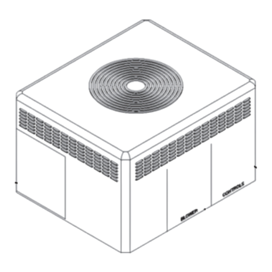
Remove Access Panels
2.
Remove these three (3) access panels
(see Figure 1):
• Control/Heat access panel
• Blower access panel
• Coil access panel
BAYRLAY006B Installation (Required for
3.
*DCZ and *WCZ units only, for *YCZ units
skip to step 4)
1. Remove wire harness that came attached to the
BAYECON Logic Module being installed.
IMPORTANT: Do NOT remove the resistors from the
Logic Module. Also, Do NOT remove the YL and YL/BK
wires connected to SO and + on the Logic Module
2. Locate the ICMC Board in the upper left hand corner
of the unit control box and the DFC board in the upper
center of the unit control box. See Figure 5.
3. Using the existing holes in the back of the unit control
box, mount the relay bracket assembly using the 2
screws supplied with the BAYRLAY006B Kit. See
Figure 5.
4. Route the BAYRLAY006B wire harness attached to the
relays to the logic module as shown in Figure 3.
5. Connect the BAYRLAY006B to the economizer Logic
Module and make the field connections as shown in
the hookup diagram for the appropriate unit model.
CAUTION
Advertisement

Related Manuals for Trane BAYECON207A


Summary of Contents for Trane BAYECON207A
- Page 1 18-HE140D1-1A-EN Installer’s Guide Horizontal Economizer and Rain Hood Model: Used with: BAYECON207A *DCZ, *WCZ, *YCZ *018-036 BAYECON208A *DCZ, *WCZ, *YCZ *042-060 BAYRLAY006B (Required with *DCZ and *WCZ models) Note: * indicates an alphanumeric character. WARNING: HAZARDOUS VOLTAGE - DISCONNECT POWER BEFORE SERVICING ALL phases of this installation must comply with NATIONAL, STATE AND LOCAL CODES IMPORTANT —...
- Page 2 Mixed Air Sensor. flanges. See Figure 2. 10. In the Control Box, locate the ICMC Board in the upper left BAYECON207A Small Cabinet - hand corner of the Control Box. Find the YL/RD and YL (*DCZ, *WCZ, *YCZ *018-036) wires in the 12 pin connector.
- Page 3 Gaskets (2) Rain Hood and Duct Mist Eliminator (Mist Eliminator not shown, located inside Rain Hood) Mixed Air Sensor NOTE: BAYECON208A economizer only contains two clearance notches in the top flange, BAYECON207A shown. Figure 2. Horizontal Economizer Assembly & Kit Contents...
- Page 4 INSTALLER’S GUIDE 1.) From 2.) Continue Routing 3.) Pull the 2 Mixed Air Sensor EconomizerAssembly, Behind Compressor Wires (with Stake-Ons) from the Pass Wire Harness Compartment and into Harness and Route Down Near Through Coil Grommet. Blower Compartment. the Mixed Air Sensor. See View A.
- Page 5 INSTALLER’S GUIDE ICMC Board Relays Figure 5. Mount BAYRLAY006B...
- Page 6 INSTALLER’S GUIDE Figure 6. 5YCZ Economizer Connection Diagram IMPORTANT — Retain this wiring diagram; please return this document to service information pack upon completion of work.
- Page 7 INSTALLER’S GUIDE Figure 7. 5DCZ/WCZ Economizer Connection Diagram IMPORTANT — Retain this wiring diagram; please return this document to service information pack upon completion of work.
- Page 8 INSTALLER’S GUIDE Figure 8. 2/4DCZ/WCZ Economizer Connection Diagram IMPORTANT-Retain this wiring diagram; please return this document to service information pack upon completion of work.
- Page 9 INSTALLER’S GUIDE Figure 9. 2/4YCZ Economizer Connection Diagram IMPORTANT-Retain this wiring diagram; please return this document to service information pack upon completion of work.
- Page 10 INSTALLER’S GUIDE Table 1. Motor Operation Checkout DRIVE MOTOR OPEN DRIVE MOTOR CLOSED SPRING RETURN Power to TR and TR1, jumper T and T1 Disconnect jumper at T or T1 and Disconnect power at TR and TR1 disconnect P or P1, if connected CONTROL POINT CONTROL APPROX.
- Page 11 INSTALLER’S GUIDE Table 2. Temp vs. OHM Values for MAS (Mixed Air Sensor) Temp vs. OHM for MAS (Mixed Air Sensor) Temp F Temp C R(K OHMS) DC Volts 33.8 9.576 3.910 35.6 9.092 3.882 37.4 8.636 3.894 39.2 8.204 3.863 41.0 7.796...
- Page 12 INSTALLER’S GUIDE CHECKOUT - For Units with a Honeywell W7212 Control CHECKOUT AND TROUBLESHOOTING W7212 Checkout requires a 9V battery, 620 ohm, 1.2K ohm, 5.6K ohm, and 6.8K ohm resistors. Use Table 4 and Fig. 12 for checkout. CAUTION Open DC VOLTMETER Equipment Damage Hazard.
- Page 13 INSTALLER’S GUIDE Table 3. Checkout for W7212, W7213, W7214 Economizer Connected to Honeywell Actuator (Cont.) Step Checkout Procedure Proper Response DIFFERENTIAL ENTHALPY Execute stop one, Checkout Preparation. ― Turn DCV MAX to mid position. Place 620 ohm resistor across S and + (white sleeve resistor makes OA enthalpy low).
- Page 14 INSTALLER’S GUIDE Dampers will not open beyond minimum position during 1 stage cooling. Jumper across the Ambient must be below 70F to activate Is OD ambient OAS terminals to Is OAS closed? economizer beyond minimum position fresh below 70F? close circuit air opening.
- Page 15 INSTALLER’S GUIDE Compressor will not energize when space conditions rise. Install a 2 stage thermostat and Is a 2-stage Is thermostat's Y2 Wire per Installer's wire according to economizer thermostat connected to unit's YL Guide. Installer's Guide applied? Troubleshoot why Troubleshoot unit.
- Page 16 INSTALLER’S GUIDE Troubleshooting - Dampers Open With G Dampers drive to 100% open during a "Continuous Fan" call. (drives beyond minimum position setting) Ensure there is not a call for cooling. Rotate Minimum Position potentiometer fully Measure resistance of Adjust Minimum Does damper green resistor Position to desired...
- Page 17 INSTALLER’S GUIDE Troubleshooting - Mixed Air Sensor Dampers drive to 100% open although the mixed air temp is below 55F. It can be possible for the tip of the MAS to twist near the Remove MAS thermistor which causes the wires from "T"...
- Page 18 INSTALLER’S GUIDE Troubleshooting - Logic Module Failures Logic Module has repeated failures Remove MAS wires from "T" and "T1" terminals on logic module. Measure resistance from either MAS wire to cabinet ground Check other terminals for Replace MAS any continuity? shorting.
- Page 19 About Trane and American Standard Heating and Air Conditioning Trane and American Standard create comfortable, energy efficient indoor environments for residential applications. For more information, please visit www.trane.com or www.americanstandardair.com The manufacturer has a policy of continuous data improvement and it reserves the right to change design and specifications without notice. We are committed to using environmentally conscious print practices.
Need help?
Do you have a question about the BAYECON207A and is the answer not in the manual?
Questions and answers