Table of Contents
Troubleshooting

Related Manuals for ZyXEL Communications P-870HN-51B - V1.0


Summary of Contents for ZyXEL Communications P-870HN-51B - V1.0
- Page 1 P-870HN-51b 802.11n VDSL2 4-port Gateway Default Login Details IP Address http://192.168.1.1 User Name admin Password 1234 Firmware Version 1.0 www.zyxel.com Edition 1, 9/2009 www.zyxel.com Copyright © 2009 ZyXEL Communications Corporation...
-
Page 3: About This User's Guide
About This User's Guide About This User's Guide Intended Audience This manual is intended for people who want to configure the ZyXEL Device using the web configurator. Related Documentation • Quick Start Guide The Quick Start Guide is designed to help you get up and running right away. It contains information on setting up your network and configuring for Internet access. - Page 4 • Knowledge Base If you have a specific question about your product, the answer may be here. This is a collection of answers to previously asked questions about ZyXEL products. • Forum This contains discussions on ZyXEL products. Learn from others who use ZyXEL products and share your experiences as well.
-
Page 5: Document Conventions
Syntax Conventions • The P-870HN-51b may be referred to as the “ZyXEL Device”, the “device”, the “system” or the “product” in this User’s Guide. • Product labels, screen names, field labels and field choices are all in bold font. - Page 6 Document Conventions Icons Used in Figures Figures in this User’s Guide may use the following generic icons. The ZyXEL Device icon is not an exact representation of your device. ZyXEL Device Computer Notebook computer Server DSLAM Firewall Telephone Switch Router...
-
Page 7: Safety Warnings
Safety Warnings Safety Warnings • Do NOT use this product near water, for example, in a wet basement or near a swimming pool. • Do NOT expose your device to dampness, dust or corrosive liquids. • Do NOT store things on the device. •... - Page 8 Safety Warnings P-870HN-51b User’s Guide...
-
Page 9: Table Of Contents
Contents Overview Contents Overview Introduction ..........................19 Introducing the ZyXEL Device ....................21 Tutorials ............................. 27 Introducing the Web Configurator ....................49 Status Screens .......................... 55 Network ........................... 65 WAN Setup ..........................67 LAN Setup ..........................93 Wireless LAN ........................... 101 Network Address Translation (NAT) .................. - Page 10 Contents Overview P-870HN-51b User’s Guide...
-
Page 11: Table Of Contents
Introducing the ZyXEL Device ....................21 1.1 Overview ..........................21 1.2 Ways to Manage the ZyXEL Device ..................21 1.3 Good Habits for Managing the ZyXEL Device ..............22 1.4 Applications for the ZyXEL Device ..................22 1.4.1 Internet Access ......................22 1.5 LEDs (Lights) ........................ - Page 12 Table of Contents Chapter 3 Introducing the Web Configurator ..................49 3.1 Web Configurator Overview ....................49 3.1.1 Accessing the Web Configurator ................49 3.2 Web Configurator Main Screen ................... 50 3.2.1 Navigation Panel ......................51 3.2.2 Main Window ......................53 3.2.3 Status Bar ........................
- Page 13 Table of Contents 7.1 Overview ..........................101 7.1.1 What You Can Do in this Chapter ................101 7.2 What You Need to Know ....................102 7.3 Before You Begin ....................... 104 7.4 The General Screen ......................105 7.4.1 No Security ....................... 107 7.4.2 WEP Encryption .......................
- Page 14 Table of Contents 9.1.1 What You Can Do in this Chapter ................147 9.2 The MAC Filter Screen ...................... 148 9.2.1 Creating MAC Filtering Rules ................. 149 Chapter 10 Firewall........................... 151 10.1 Overview ......................... 151 10.1.1 What You Can Do in this Chapter ................151 10.2 What You Need to Know ....................
- Page 15 Table of Contents Chapter 14 RIP ............................179 14.1 Overview ........................179 14.1.1 What You Can Do in this Chapter ................179 14.2 The RIP Screen ....................... 179 Chapter 15 Quality of Service (QoS)....................... 181 15.1 Overview ......................... 181 15.1.1 What You Can Do in this Chapter ................181 15.2 What You Need to Know ....................
- Page 16 Table of Contents 18.5 Using UPnP in Windows XP Example ................209 Chapter 19 Parental Control ........................217 19.1 Overview .......................... 217 19.1.1 What You Can Do in this Chapter ................217 19.2 The Time Restriction Screen ................... 217 19.2.1 Adding a Schedule ....................218 19.3 The URL Filter Screen .....................
- Page 17 24.5 The OAM Ping Test Screen ..................... 249 Chapter 25 Troubleshooting........................251 25.1 Power, Hardware Connections, and LEDs ..............251 25.2 ZyXEL Device Access and Login ..................252 25.3 Internet Access ........................ 253 25.4 Wireless LAN Troubleshooting ..................255 Chapter 26 Product Specifications ......................
- Page 18 Table of Contents P-870HN-51b User’s Guide...
-
Page 19: Introduction
Introduction Introducing the ZyXEL Device (21) Tutorials (27) Introducing the Web Configurator (49) Status Screens (55) -
Page 21: Introducing The Zyxel Device
H A P T E R Introducing the ZyXEL Device This chapter introduces the main applications and features of the ZyXEL Device. It also introduces the ways you can manage the ZyXEL Device. 1.1 Overview The ZyXEL Device is a VDSL2 gateway that allows super-fast, secure Internet access over analog (POTS) telephone lines. -
Page 22: Good Habits For Managing The Zyxel Device
1.3 Good Habits for Managing the ZyXEL Device Do the following things regularly to make the ZyXEL Device more secure and to manage the ZyXEL Device more effectively. • Change the password. Use a password that’s not easy to guess and that consists of different types of characters, such as numbers and letters. - Page 23 Chapter 1 Introducing the ZyXEL Device WAN services over one ADSL or VDSL line. The ZyXEL Device cannot work in ADSL and VDSL mode at the same time. Figure 1 ZyXEL Device’s Internet Access Application Bridging IPoE PPPoE Internet ADSL / VDSL...
-
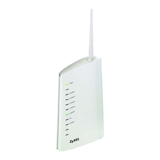
Page 24: Leds (Lights)
Chapter 1 Introducing the ZyXEL Device 1.5 LEDs (Lights) The following graphic displays the labels of the LEDs. Figure 2 The Front Panel of the Device: P-870HN-51b User’s Guide... -
Page 25: The Reset Button
Chapter 1 Introducing the ZyXEL Device None of the LEDs are on if the ZyXEL Device is not receiving power. Table 1 LED Descriptions COLOR STATUS DESCRIPTION POWER Green The ZyXEL Device is receiving power and ready for use. Blinking The ZyXEL Device is self-testing. -
Page 26: Using The Reset Button
The WLAN/WPS LED should flash while the ZyXEL Device sets up a WPS connection with the wireless device. Note: You must activate WPS in the ZyXEL Device and in another wireless device within two minutes of each other. See Section 7.10.4 on page 125 for more information. -
Page 27: Tutorials
An access point (AP) or wireless router is referred to as “AP” and a computer with a wireless network card or USB/PCI adapter is referred to as “wireless client” here. We use the ZyXEL Device web screens and M-302 utility screens as an example. The screens may vary slightly for different models. - Page 28 Chapter 2 Tutorials Open the Network > Wireless LAN screen in the AP’s web configurator. Figure 3 AP: Wireless LAN Make sure the Active Wireless LAN check box is selected. Enter “SSID_Example3” as the SSID and select a channel which is not used by another AP.
- Page 29 Chapter 2 Tutorials Click the Advanced Setup tab and select 802.11b/g Mixed in the 802.11 Mode field. Click Apply. Figure 4 AP: Wireless LAN > Advanced Setup Open the Status screen.Verify your wireless and wireless security settings under Device Information and check if the WLAN connection is up under Interface Status.
-
Page 30: Configuring The Wireless Client
This section describes how to connect the wireless client to a network. 2.1.3.1 Connecting to a Wireless LAN The following sections show you how to join a wireless network using the ZyXEL utility, as in the following diagram. The wireless client is labeled C and the access point is labeled AP. - Page 31 After you install the ZyXEL utility and then insert the wireless client, follow the steps below to connect to a network using the Site Survey screen. Open the ZyXEL utility and click the Site Survey tab to open the screen shown next.
- Page 32 Use the Next button to move on to the next screen. You can use the Back button at any time to return to the previous screen, or the Exit button to return to the Site Survey screen. Figure 8 ZyXEL Utility: Security Settings The Confirm Save window appears. Check your settings and click Save to continue.
- Page 33 Chapter 2 Tutorials The ZyXEL utility returns to the Link Info screen while it connects to the wireless network using your settings. When the wireless link is established, the ZyXEL utility icon in the system tray turns green and the Link Info screen displays details of the active connection.
- Page 34 Chapter 2 Tutorials Open the ZyXEL utility and click the Profile tab to open the screen shown next. Click Add to configure a new profile. Figure 11 ZyXEL Utility: Profile The Add New Profile screen appears. The wireless client automatically searches for available wireless networks, which are displayed in the Scan Info box.
- Page 35 Choose the same encryption method as the AP to which you want to connect (In this example, WPA-PSK). Figure 13 ZyXEL Utility: Profile Security This screen varies depending on the encryption method you selected in the previous screen. Enter the pre-shared key and leave the encryption type at the default setting.
- Page 36 Note: Only one profile can be activated and used at any given time. Figure 17 Profile: Activate When you activate the new profile, the ZyXEL utility returns to the Link Info screen while it connects to the AP using your settings. When the wireless link is established, the ZyXEL utility icon in the system tray turns green and the Link Info screen displays details of the active connection.
-
Page 37: How To Set Up Multiple Vdsl Connection Groups
Chapter 2 Tutorials 2.2 How to Set up Multiple VDSL Connection Groups This tutorial shows you how to set up two VDSL WAN connections for two LAN groups. GR1 will use VDSL connection 1. GR2 will use VDSL connection 2. There is also a third default group that has no WAN connection associated to it. - Page 38 Chapter 2 Tutorials 2.2.1.1 Adding a PTM/Bridge WAN Service Click Network > WAN > Layer 2 Interface. Select PTM as your interface, then click Add. Select the MSC Mode as the PTM Connection Mode. Then click Apply/Save. The PTM interface is added to the Layer 2 Interface screen. Click Network > WAN >...
- Page 39 Chapter 2 Tutorials Select Bridging as the WAN service type. Then click Next to finish the setup. The WAN setup summary is displayed. If the settings are correct, click Apply/ Save. The PTM/Bridge WAN connection is configured successfully. The Internet Connection screen should look like the following.
- Page 40 Chapter 2 Tutorials 2.2.1.2 Adding a PTM/PPPoE WAN Service Click Network > WAN > Internet Connection and click Add. Select PTM0/(0_0_1) as the layer 2 interface for this service and click Next. Select PPP over Ethernet as the WAN service type. Then click Next. P-870HN-51b User’s Guide...
- Page 41 Chapter 2 Tutorials Configure the PPP User and Password screen. The PPP Username is Service@ISP.net, the PPP Password is 1234, and the PPPoE Service Name is User. Click Next when you finish the settings. Select pppoe_0_0_1_2/ppp0_2 as the WAN Interface. Then click Next. Obtain DNS from the PPPoE WAN interface that you selected.
-
Page 42: Setting Interface Groups
Chapter 2 Tutorials The WAN setup summary is displayed. If the settings are correct, click Apply/ Save. The PTM/PPPoE WAN connection is configured successfully. The Internet Connection screen should look like the following. 2.2.2 Setting Interface Groups This part shows examples of creating multiple networks groups with the WAN services that you have configured in the previous section. - Page 43 Chapter 2 Tutorials Click Advanced Setup > Interface Group to open the following screen. Click Add to create a new interface group GR1. Enter GR1 as the Group Name. In this group, we will associate PTM/Bridge as the WAN interface with LAN1 and WL_ZyXEL01 (WLAN) as the LAN interfaces. Select br_0_0_1_1/ptm0_1(VDSL1) from the WAN Interface drop-down list.
- Page 44 Chapter 2 Tutorials GR1 has been added successfully to the interface group list. Click Add to create another interface group: GR2. Enter GR2 as the Group Name. In this group, we will associate PTM/PPPoE as the WAN interface with LAN3 and LAN4 as the LAN interfaces. Select pppoe_0_0_1_2/ppp0_2 (VDSL2) from the WAN Interface drop-down list.
- Page 45 Chapter 2 Tutorials GR2 has been added successfully to the interface group list. The screen should look like the following. P-870HN-51b User’s Guide...
-
Page 46: Configuring Interface Group Ip
Chapter 2 Tutorials 2.2.3 Configuring Interface Group IP Click Network > LAN > IP. Select GR1 from the GroupName drop-down list. The IP Address (192.168.2.1) and IP Subnet Mask (255.255.255.0) is obtained automatically. P-870HN-51b User’s Guide... -
Page 47: Testing The Vdsl Connection Groups
Select GR2 from the GroupName drop-down list. The IP Address (192.168.3.1) and IP Subnet Mask (255.255.255.0) is obtained automatically. Select Active DHCP and DHCP Server to have the ZyXEL Device act as the DHCP server for the network. Click Apply when you finish the settings. - Page 48 Chapter 2 Tutorials P-870HN-51b User’s Guide...
-
Page 49: Introducing The Web Configurator
Internet Explorer. 3.1.1 Accessing the Web Configurator Make sure your ZyXEL Device hardware is properly connected (refer to the Quick Start Guide). Launch your web browser. Type "http://192.168.1.1" as the URL. -
Page 50: Web Configurator Main Screen
Figure 18 Password Screen 3.2 Web Configurator Main Screen This guide uses the P-870HN-51b screenshots as an example. The screens may vary slightly for different ZyXEL Device models. Figure 19 Main Screen P-870HN-51b User’s Guide... -
Page 51: Navigation Panel
• C - main window • D - status bar 3.2.1 Navigation Panel Use the menu items on the navigation panel to open screens to configure ZyXEL Device features. The following tables describe each menu item. Table 3 Navigation Panel Summary... - Page 52 This screen allows you to use a static hostname alias for a dynamic IP address. Remote TR069 Use this screen to configure the ZyXEL Device to be managed by MGMT an ACS (Auto Configuration Server). TR064 Use this screen to enable management via TR-064 on the LAN.
-
Page 53: Main Window
Configuration Use this screen to backup and restore your device’s configuration (settings) or reset the factory default settings. Restart This screen allows you to reboot the ZyXEL Device without turning the power off. Diagnostic General Use this screen to test the connections to other devices. - Page 54 Chapter 3 Introducing the Web Configurator P-870HN-51b User’s Guide...
-
Page 55: Status Screens
H A P T E R Status Screens Use the Status screens to look at the current status of the device, system resources and interfaces (LAN and WAN). The Status screen also provides detailed information from DHCP and statistics from traffic. 4.1 Status Screen Click Status to open this screen. - Page 56 This field displays what DHCP services the ZyXEL Device is providing to the LAN. Choices are: Server - The ZyXEL Device is a DHCP server in the LAN. It assigns IP addresses to other computers in the LAN. Relay - The ZyXEL Device acts as a surrogate DHCP server and relays DHCP requests and responses between the remote server and the clients.
- Page 57 This field displays how long the ZyXEL Device has been running since it Uptime last started up. The ZyXEL Device starts up when you plug it in, when you restart it (Maintenance > Tools > Restart), or when you reset it (see Section 1.6 on page...
- Page 58 For the DSL interface, this field displays LinkDown (line is down) or Up (line is up or connected). For the LAN interface, this field displays Up when the ZyXEL Device is using the interface and NoLink when the line is disconnected.
-
Page 59: Wan Service Statistics
The default name ipoa*, pppoa*, atm* or ptm* indicates the DSL port. pppx (where x starts from 0 and is the index number of PPP connection on the ZyXEL Device) indicates a PPP connection via any one of the WAN interface. -
Page 60: Route Info
Click Stop to stop refreshing statistics. 4.1.2 Route Info Routing is based on the destination address only and the ZyXEL Device takes the shortest path to forward a packet. Click Status > Route Info to access this screen. Use this screen to view the internal routing table on the ZyXEL Device. - Page 61 Chapter 4 Status Screens Table 6 Status > Route Info (continued) LABEL DESCRIPTION Flag This indicates the route status. Up: The route is up. !(Reject): The route is blocked and will force a route lookup to fail. Gateway: The route uses a gateway to forward traffic. Host: The target of the route is a host.
-
Page 62: Wlan Station List
4.1.3 WLAN Station List Click Status > WLAN Station List to access this screen. Use this screen to view the wireless stations that are currently associated to the ZyXEL Device. Figure 23 Status > WLAN Station List The following table describes the labels in this screen. -
Page 63: Lan Statistics
Chapter 4 Status Screens 4.1.4 LAN Statistics Click Status > LAN Statistics to access this screen. Use this screen to view the LAN statistics. Figure 24 Status > LAN Statistics The following table describes the labels in this screen. Table 8 Status > LAN Statistics LABEL DESCRIPTION Interface... -
Page 64: Client List
TCP/IP configuration at start-up from a server. You can configure the ZyXEL Device as a DHCP server or disable it. When configured as a server, the ZyXEL Device provides the TCP/IP configuration for the clients. If DHCP service is disabled, you must have another DHCP server on your LAN, or else the computer must be manually configured. -
Page 65: Network
Network WAN Setup (67) LAN Setup (93) Wireless LAN (101) Network Address Translation (NAT) (133) -
Page 67: Wan Setup
H A P T E R WAN Setup 5.1 Overview This chapter discusses the ZyXEL Device’s WAN screens. Use these screens to configure your ZyXEL Device for Internet access. A WAN (Wide Area Network) connection is an outside connection to another network or the Internet. -
Page 68: What You Need To Know
WAN IP Address The WAN IP address is an IP address for the ZyXEL Device, which makes it accessible from an outside network. It is used by the ZyXEL Device to communicate with other devices in other networks. It can be static (fixed) or dynamically assigned by the ISP each time the ZyXEL Device tries to access the Internet. -
Page 69: The Layer 2 Interface Screen
Chapter 5 WAN Setup 5.4 The Layer 2 Interface Screen The ZyXEL Device must have a layer-2 interface to allow users to use the DSL port to access the Internet. The screen varies depending on the interface type you select. -
Page 70: Layer 2 Interface Configuration
Use this screen to create a new layer-2 interface. At the time of writing, you can configure only one PTM interface on the ZyXEL Device. You can have multiple ATM layer-2 interfaces using different VPI and/or VCI values. The screen varies depending on the interface type you select. - Page 71 Chapter 5 WAN Setup Figure 29 DSL ATM Interface Configuration Figure 30 DSL PTM Interface Configuration P-870HN-51b User’s Guide...
- Page 72 • VC/MUX: In VC multiplexing, each protocol is carried on a single ATM virtual circuit (VC). To transport multiple protocols, the ZyXEL Device needs separate VCs. There is a binding between a VC and the type of the network protocol carried on the VC. This reduces payload overhead since there is no need to carry protocol information in each Protocol Data Unit (PDU) payload.
-
Page 73: The Internet Connection Screen
WAN > Internet Connection. The summary table shows you the configured WAN services (connections) on the ZyXEL Device. To use NAT, firewall or IGMP proxy in the ZyXEL Device, you need to configure a WAN connection with PPPoE or IPoE. - Page 74 A default name ipoa*, pppoa*, atm* or ptm* indicates DSL port. The pppx name (where x starts from 0 and is the index number of PPP connection on the ZyXEL Device) indicates a PPP connection via any one of the WAN interface.
-
Page 75: Wan Interface
Chapter 5 WAN Setup Table 12 Internet Connection LABEL DESCRIPTION IGMP This shows whether IGMP (Internet Group Multicast Protocol) is activated or not for this connection. IGMP is not available when the connection uses the bridging service. This shows whether NAT is activated or not for this interface. NAT is not available when the connection uses the bridging service. -
Page 76: Service Type
Chapter 5 WAN Setup 5.5.1.2 Service Type If you set the DSL link type to PPPoA or IPoA for the ATM interface and configure a WAN connection using the ATM interface, you only need to configure the Enter Service Description field in this screen. Figure 33 WAN Configuration: Service Type Figure 34 The following table describes the labels in this screen. - Page 77 Chapter 5 WAN Setup Table 14 WAN Configuration: Service Type LABEL DESCRIPTION Enter 802.1Q Type the VLAN ID number (from 1 to 4094) for traffic through this VLAN ID connection. This field is available when the PTM interface is in VLANMUX mode. Back Click this button to return to the previous screen.
- Page 78 MSCHAP - Your ZyXEL Device accepts MSCHAP only. MS-CHAP is the Microsoft version of the CHAP. Enable Fullcone Select this option to enable full cone NAT on the ZyXEL Device. Dial on Demand Select this check box when you do not want the connection up all the time and specify an idle time-out in the Inactivity Timeout field.
-
Page 79: Configuration Screen
ISP. This field is not available for a PPPoA connection. Enable IGMP Select this check box to have the ZyXEL Device act as an IGMP proxy Multicast Proxy on this connection. This allows the ZyXEL Device to get subscribing information and maintain a joined member list for each multicast group. - Page 80 Enable DHCP Select this to identify the vendor and functionality of the ZyXEL Device Option 60 in DHCP requests that the ZyXEL Device sends to a DHCP server when getting a WAN IP address. Vendor Class Enter the Vendor Class Identifier (Option 60), such as the type of the Identifier hardware or firmware.
- Page 81 Chapter 5 WAN Setup IPoA This screen displays only when you set the DSL link type to IPoA for Figure 37 the ATM interface and configure a WAN connection using the ATM interface. The following table describes the labels in this screen. Table 17 WAN Configuration: IPoA LABEL DESCRIPTION...
-
Page 82: Default Gateway
Enable Firewall Select this check box to activate Firewall on this connection. Enable IGMP Select this check box to have the ZyXEL Device act as an IGMP proxy Multicast Proxy on this connection. This allows the ZyXEL Device to get subscribing information and maintain a joined member list for each multicast group. - Page 83 The following table describes the labels in this screen. Table 20 WAN Configuration: DNS Server: PPPoE or IPoE LABEL DESCRIPTION Obtain DNS info Select this to have the ZyXEL Device get the DNS server addresses from a WAN from the ISP automatically. interface WAN interface This displays the WAN interface you selected in the previous screen.
-
Page 84: Configuration Summary
Chapter 5 WAN Setup 5.5.1.7 Configuration Summary This read-only screen shows the current WAN connection settings. Figure 41 WAN Configuration: Configuration Summary The following table describes the labels in this screen. Table 21 WAN Configuration: Configuration Summary LABEL DESCRIPTION Connection Type This is the encapsulation method used by this connection. -
Page 85: Technical Reference
Device features described in this chapter. Encapsulation Be sure to use the encapsulation method required by your ISP. The ZyXEL Device can work in bridge mode or routing mode. When the ZyXEL Device is in routing mode, it supports the following methods. IP over Ethernet IP over Ethernet (IPoE) is an alternative to PPPoE. - Page 86 Chapter 5 WAN Setup since the ZyXEL Device does that part of the task. Furthermore, with NAT, all of the LANs’ computers will have access. PPPoA PPPoA stands for Point to Point Protocol over ATM Adaptation Layer 5 (AAL5). A PPPoA connection functions like a dial-up Internet connection.
- Page 87 Chapter 5 WAN Setup Peak Cell Rate (PCR) is the maximum rate at which the sender can send cells. This parameter may be lower (but not higher) than the maximum line speed. 1 ATM cell is 53 bytes (424 bits), so a maximum speed of 832Kbps gives a maximum PCR of 1962 cells/sec.
- Page 88 IP address and port to the internal IP address and port. In the following example, the ZyXEL Device maps the source address of all packets sent from the internal IP address 1 and port A to IP address 2 and port B on the external network.
- Page 89 A to IP address 2 and port B on the external network for packets sent to IP address 3 and port C. The ZyXEL Device uses a different mapping (IP address 2 and port M) for packets sent to IP address 4 and port...
- Page 90 Chapter 5 WAN Setup the example, only 3, C is allowed to send packets to 2, B and only 4, D is allowed to send packets to 2, M. Figure 44 Symmetric NAT 3, C 2, B 4, D 1, A 2, M 4, E 5, B...
- Page 91 IP hosts (including gateways). All hosts must join the 224.0.0.1 group in order to participate in IGMP. The address 224.0.0.2 is assigned to the multicast routers group. At start up, the ZyXEL Device queries all directly connected networks to gather group membership. After that, the ZyXEL Device periodically updates this information.
- Page 92 DNS server fields. If your ISP dynamically assigns the DNS server IP addresses (along with the ZyXEL Device’s WAN IP address), set the DNS server fields to get the DNS server address from the ISP. P-870HN-51b User’s Guide...
-
Page 93: Lan Setup
6.1.1 What You Can Do in this Chapter The LAN IP screen lets you set the LAN IP address and subnet mask of your ZyXEL device and configure other LAN TCP/IP settings (Section 6.3 on page 95). P-870HN-51b User’s Guide... -
Page 94: What You Need To Know
DHCP client capability. DHCP Relay You can also configure the ZyXEL Device to relay client DHCP requests to a DHCP server and the server’s responses back to the clients. RIP (Routing Information Protocol) allows a router to exchange routing information with other routers. -
Page 95: The Lan Ip Screen
Click Network > LAN to open the IP screen. See Section 6.4 on page 97 background information. Use this screen to set the Local Area Network IP address and subnet mask of your ZyXEL Device. Figure 45 LAN > IP P-870HN-51b User’s Guide... - Page 96 DNS Servers Assigned by DHCP Server If you do not configure DNS servers, the ZyXEL Device uses its LAN IP address and tells the DHCP clients on the LAN that itself is the DNS server. When a LAN client sends a DNS query to the ZyXEL Device, the ZyXEL Device forwards the query to its system DNS server you configured in the WAN screen.
-
Page 97: Technical Reference
TCP/IP configuration at start-up from a server. You can configure the ZyXEL Device as a DHCP server or disable it. When configured as a server, the ZyXEL Device provides the TCP/IP configuration for the clients. If you turn DHCP service off, you must have another DHCP server on your LAN, or else the computer must be manually configured. - Page 98 Chapter 6 LAN Setup IP Pool Setup The ZyXEL Device is pre-configured with a pool of IP addresses for the DHCP clients (DHCP Pool). See the product specifications in the appendices. Do not assign static IP addresses from the DHCP pool to your LAN computers.
- Page 99 IGMP. The address 224.0.0.2 is assigned to the multicast routers group. The ZyXEL Device supports both IGMP version 1 (IGMP-v1) and IGMP version 2 (IGMP-v2). At start up, the ZyXEL Device queries all directly connected networks to gather group membership. After that, the ZyXEL Device periodically updates this information.
- Page 100 IP alias allows you to partition a physical network into different logical networks over the same Ethernet interface. The ZyXEL Device supports three logical LAN interfaces via its single physical Ethernet interface with the ZyXEL Device itself as the gateway for each LAN network.
-
Page 101: Wireless Lan
105). You can also configure the MAC filter to allow or block access to the ZyXEL Device based on the MAC addresses of the wireless stations. • The More AP screen lets you set up multiple wireless networks on your ZyXEL Device (Section 7.5 on page... -
Page 102: What You Need To Know
Chapter 7 Wireless LAN • The WDS screen lets you set up a Wireless Distribution System, in which the ZyXEL Device acts as a bridge with other ZyXEL access points (Section 7.8 on page 117). • The Advanced Setup screen lets you change the wireless mode, and make other advanced wireless configuration changes (Section 7.9 on page... - Page 103 Chapter 7 Wireless LAN network’s name. This helps you identify your wireless network when wireless networks’ coverage areas overlap and you have a variety of networks to choose from. Radio Channels In the radio spectrum, there are certain frequency bands allocated for unlicensed, civilian use.
-
Page 104: Before You Begin
Chapter 7 Wireless LAN A good way to come up with effective security keys, passwords and so on is to use obscure information that you personally will easily remember, and to enter it in a way that appears random and does not include real words. For example, if your mother owns a 1970 Dodge Challenger and her favorite movie is Vanishing Point (which you know was made in 1971) you could use “70dodchal71vanpoi”... -
Page 105: The General Screen
Chapter 7 Wireless LAN 7.4 The General Screen Note: If you are configuring the ZyXEL Device from a computer connected to the wireless LAN and you change the ZyXEL Device’s SSID or security settings, you will lose your wireless connection when you press Apply to confirm. You must then change the wireless settings of your computer to match the ZyXEL Device’s new settings. - Page 106 Wireless multicast traffic. Multicast Forwarding (WMF) BSSID This shows the MAC address of the wireless interface on the ZyXEL Device when wireless LAN is enabled. Security See the following sections for more details about this field. Mode MAC Filter Click this button to go to the MAC Filter screen to configure whether the wireless devices with the MAC addresses listed are allowed or denied to access the ZyXEL Device using this SSID.
-
Page 107: No Security
Select No Security to allow wireless devices to communicate with the access points without any data encryption or authentication. Note: If you do not enable any wireless security on your ZyXEL Device, your network is accessible to any wireless networking device that is within range. -
Page 108: Wep Encryption
Chapter 7 Wireless LAN 7.4.2 WEP Encryption In order to configure and enable WEP encryption; click Network > Wireless LAN to display the General screen. Select WEP from the Security Mode list. Figure 50 Wireless LAN > General: Static WEP Encryption The following table describes the wireless LAN security labels in this screen. -
Page 109: Wpa(2)-Psk
Key 1 to Key The WEP key is used to secure your data from eavesdropping by unauthorized wireless users. Both the ZyXEL Device and the wireless stations must use the same WEP key for data transmission. Only one key can be activated at any one time. Select a default key to use for data encryption. - Page 110 WEP key for an AP and all stations in a WLAN on a periodic basis. Setting of the Group Key Update Timer is also supported in WPA(2)- PSK mode. The ZyXEL Device default is 1800 seconds (30 minutes). P-870HN-51b User’s Guide...
-
Page 111: Wpa(2) Authentication
DESCRIPTION Security Mode Choose WPA or WPA2 from the drop-down list box. Active Compatible This field is only available for WPA2. Select this if you want the ZyXEL Device to support WPA and WPA2 simultaneously. Encryption Select the encryption type (TKIP, AES or TKIP+AES) for data encryption. -
Page 112: Mac Filter
ZyXEL Device. The key is not sent over the network. 7.4.5 MAC Filter This screen allows you to configure the ZyXEL Device to give exclusive access to specific devices (Allow) or exclude specific devices from accessing the ZyXEL Device (Deny). Every Ethernet device has a unique MAC (Media Access Control) address. -
Page 113: Adding A New Mac Filtering Rule
Chapter 7 Wireless LAN Use this screen to change your ZyXEL Device’s MAC filter settings. Click the Edit button in the Wireless LAN > General screen. The following screen displays. Figure 53 Wireless LAN > MAC Filter The following table describes the labels in this screen. -
Page 114: The More Ap Screen
Select the check box to activate an SSID profile. SSID An SSID profile is the set of parameters relating to one of the ZyXEL Device’s BSSs. The SSID (Service Set IDentifier) identifies the Service Set with which a wireless device is associated. -
Page 115: More Ap Edit
7.6 The WPS Screen Use this screen to configure WiFi Protected Setup (WPS) on your ZyXEL Device. WPS allows you to quickly set up a wireless network with strong security, without having to configure security settings manually. -
Page 116: The Wps Station Screen
WPS. The PIN is not necessary when you use WPS push-button method. Generate Click this button to have the ZyXEL Device create a new PIN. WPS Status This displays Configured when the ZyXEL Device has connected to a wireless network using WPS or Enable WPS is selected and wireless or wireless security settings have been changed. -
Page 117: The Wds Screen
A Wireless Distribution System (WDS) is a wireless connection between two or more APs. Use this screen to set up your WDS links between the ZyXEL Devices. You need to know the MAC address of the peer device. Once the security settings of peer sides match one another, the connection between the devices is made. - Page 118 Chapter 7 Wireless LAN Note: At the time of writing, WDS is only compatible with other ZyXEL Devices of the same model. Click Network > Wireless LAN > WDS. The following screen displays. WDS is turned on and this screen is configurable when the ZyXEL Device's wireless security mode is No Security or WEP.
-
Page 119: The Advanced Setup Screen
DESCRIPTION This is available only when you select Enabled(Scan) in the Bridge Restrict field. Select the check box and click Apply to have the ZyXEL Device establish a wireless link with the selected wireless device. SSID This is available only when you select Enabled(Scan) in the Bridge Restrict field. - Page 120 Allowed Output Power Set the output power of the ZyXEL Device. If there is a high density of APs in an area, decrease the output power to reduce interference with other APs. Select one of the following 20%, 40%, 60%, 80% or 100%.
-
Page 121: Technical Reference
Select a preamble type from the drop-down list menu. Choices are Long or Short. The default setting is Long. See the appendix for more information. This field is not configurable and the ZyXEL Device uses Short when you set 802.11 Mode to 802.11g Only or 802.11n Only. Apply Click this to save your changes back to the ZyXEL Device. -
Page 122: Additional Wireless Terms
The wireless network is the part in the blue circle. In this wireless network, devices A and B use the access point (AP) to interact with the other devices (such as the printer) or with the Internet. Your ZyXEL Device is the AP. Every wireless network must follow these basic guidelines. -
Page 123: Wireless Security Overview
Normally, the ZyXEL Device acts like a beacon and regularly broadcasts the SSID in the area. You can hide the SSID instead, in which case the ZyXEL Device does not broadcast the SSID. In addition, you should change the default SSID to something that is difficult to guess. - Page 124 Usually, you should set up the strongest encryption that every device in the wireless network supports. For example, suppose you have a wireless network with the ZyXEL Device and you do not have a RADIUS server. Therefore, there is no authentication. Suppose the wireless network has two devices. Device A only supports WEP, and device B supports WEP and WPA.
-
Page 125: Wifi Protected Setup
7.10.4 WiFi Protected Setup Your ZyXEL Device supports WiFi Protected Setup (WPS), which is an easy way to set up a secure wireless network. WPS is an industry standard specification, defined by the WiFi Alliance. -
Page 126: Pin Configuration
Chapter 7 Wireless LAN Press the button on one of the devices (it doesn’t matter which). For the ZyXEL Device you must press the WPS button for more than three seconds. Within two minutes, press the button on the other device. The registrar sends the network name (SSID) and security key through an secure connection to the enrollee. - Page 127 Chapter 7 Wireless LAN Start WPS on both devices within two minutes. Note: Use the configuration utility to activate WPS, not the push-button on the device itself. On a computer connected to the wireless client, try to connect to the Internet. If you can connect, WPS was successful.
-
Page 128: How Wps Works
Chapter 7 Wireless LAN 7.10.4.3 How WPS Works When two WPS-enabled devices connect, each device must assume a specific role. One device acts as the registrar (the device that supplies network and security settings) and the other device acts as the enrollee (the device that receives network and security settings. -
Page 129: Example Wps Network Setup
Chapter 7 Wireless LAN Note that the access point (AP) is not always the registrar, and the wireless client is not always the enrollee. All WPS-certified APs can be a registrar, and so can some WPS-enabled wireless clients. By default, a WPS devices is “unconfigured”. This means that it is not part of an existing network and can act as either enrollee or registrar (if it supports both functions). - Page 130 Chapter 7 Wireless LAN already has security information for the network). AP1 supplies the existing security information to Client 2. Figure 65 WPS: Example Network Step 2 REGISTRAR EXISTING CONNECTION CLIENT 1 ENROLLEE CLIENT 2 In step 3, you add another access point (AP2) to your network. AP2 is out of range of AP1, so you cannot use AP1 for the WPS handshake with the new access point.
-
Page 131: Limitations Of Wps
Chapter 7 Wireless LAN 7.10.4.5 Limitations of WPS WPS has some limitations of which you should be aware. • WPS works in Infrastructure networks only (where an AP and a wireless client communicate). It does not work in Ad-Hoc networks (where there is no AP). •... - Page 132 Chapter 7 Wireless LAN P-870HN-51b User’s Guide...
-
Page 133: Network Address Translation (Nat)
• The Port Forwarding screen lets you configure forward incoming service requests to the server(s) on your local network (Section 8.3 on page 134). • The Trigger Port screen lets you change the ZyXEL Device's trigger port settings (Section 8.4 on page 137). -
Page 134: The Port Forwarding Screen
Chapter 8 Network Address Translation (NAT) Port Forwarding A port forwarding set is a list of inside (behind NAT on the LAN) servers, for example, web or FTP, that you can make visible to the outside world even though NAT makes your whole inside network appear as a single computer to the outside world. - Page 135 To forward a series of ports, enter the last port number in a series that begins with the port number in the External Port Start field above. Internal Port Enter the port number to which you want the ZyXEL Device to translate Start the incoming port.
-
Page 136: The Port Forwarding Edit Screen
Click the Remove icon to delete an existing port forwarding rule. Note that subsequent rules move up by one when you take this action. Apply Click Apply to save your changes back to the ZyXEL Device. Cancel Click Cancel to return to the previous configuration. -
Page 137: The Trigger Port Screen
External Start Port field above. Internal Start Enter the port number here to which you want the ZyXEL Device to Port translate the incoming port. For a range of ports, enter the first number of the range to which you want the incoming ports translated. - Page 138 WAN port receives a response with a specific port number and protocol ("open" port), the ZyXEL Device forwards the traffic to the LAN IP address of the computer that sent the request. After that computer’s connection for that service closes, another computer on the LAN can use the service in the same manner.
- Page 139 Trigger Port The trigger port is a port (or a range of ports) that causes (or triggers) the ZyXEL Device to record the IP address of the LAN computer that sent the traffic to a server on the WAN. Start This is the first port number that identifies a service.
-
Page 140: Trigger Port Configuration
Click the Remove icon to delete an existing rule. Note that subsequent rules move up by one when you take this action. Apply Click Apply to save your changes back to the ZyXEL Device. Cancel Click Cancel to return to the previous configuration. - Page 141 The trigger port is a port (or a range of ports) that causes (or triggers) the Start Port ZyXEL Device to record the IP address of the LAN computer that sent the traffic to a server on the WAN. Type a port number or the starting port number in a range of port numbers.
-
Page 142: The Dmz Host Screen
SIP calls to pass through NAT by examining and translating IP addresses embedded in the data stream. The SIP ALG translates the ZyXEL Device’s private IP address inside the SIP data stream to a public IP address. You do not need to use STUN or an outbound proxy if you enable the SIP ALG. -
Page 143: Technical Reference
Chapter 8 Network Address Translation (NAT) Use this screen to enable or disable the SIP (VoIP) ALG in the ZyXEL Device. To access this screen, click NAT > ALG. Figure 73 NAT > ALG Each field is described in the following table. - Page 144 Chapter 8 Network Address Translation (NAT) Table 43 Services and Port Numbers SERVICES PORT NUMBER SNMP trap PPTP (Point-to-Point Tunneling Protocol) 1723 Port Forwarding Example Let's say you want to assign ports 21-25 to one FTP, Telnet and SMTP server (A in the example), port 80 to another (B in the example) and assign a default server IP address of 192.168.1.35 to a third (C in the example).
-
Page 145: Security
Security MAC Filter (147) Firewall (151) Certificate (157) -
Page 147: Mac Filter
MAC Filter This chapter discusses MAC address filtering. 9.1 Overview MAC filtering means sifting traffic going through the ZyXEL Device based on the source and/or destination MAC addresses. 9.1.1 What You Can Do in this Chapter The MAC Filter screen lets you view and configure the MAC filtering rules (Section 9.2 on page... -
Page 148: The Mac Filter Screen
This displays the interface to which this rule is applied. Policy This displays the MAC filtering policy for each WAN interface in bridge mode on the ZyXEL Device. By default, the ZyXEL Device allows all frames to pass through the bridge connection. Change Select the check box next to the interface for which you want to change the MAC filtering policy. -
Page 149: Creating Mac Filtering Rules
Chapter 9 MAC Filter Table 44 MAC Filter (continued) LABEL DESCRIPTION Source MAC This displays the source MAC address to which this rule applies. Please note that a blank source address is equivalent to Any. Frame Direction This displays the direction of travel of frame to which this rule applies. Remove Select the rule(s) you want to delete in the Remove column and then click the Remove button. - Page 150 Chapter 9 MAC Filter Table 45 MAC Filtering: Add (continued) LABEL DESCRIPTION WAN Interfaces Select the WAN interface to which this rule applies. Save/Apply Click Save/Apply to save your customized settings and exit this screen. P-870HN-51b User’s Guide...
-
Page 151: Firewall
H A P T E R Firewall 10.1 Overview This chapter shows you how to enable and configure the ZyXEL Device firewall settings. The ZyXEL Device firewall is a packet filtering firewall and restricts access based on the source/destination computer network address of a packet and the type of application. -
Page 152: The Firewall Screen
These custom rules work by comparing the Source IP address, Destination IP address and IP protocol type of network traffic to rules set by the administrator. Your customized rules take precedence and override the ZyXEL Device’s default rules. 10.3 The Firewall Screen Click Security >... - Page 153 DESCRIPTION Active Firewall Select this check box to enable the firewall on the ZyXEL Device. When the firewall is enabled, the ZyXEL Device blocks all incoming traffic from the WAN to the LAN. Create custom rules below to allow certain WAN users to access your LAN or to allow traffic from the WAN to a certain computer on the LAN.
-
Page 154: Creating Incoming Firewall Rules
Chapter 10 Firewall 10.3.1 Creating Incoming Firewall Rules In the Incoming screen, click Add to display this screen and refer to the following table for information on the labels. Figure 78 Firewall > Incoming: Add The following table describes the labels in this screen. Table 48 Firewall >... - Page 155 Subnet Mask Destination Port Enter the port number of the destination. Interface Select Select All to apply the rule to all interfaces on the ZyXEL Device or select the specific WAN interface(s) to which this rule applies. Back Click Back to return to the previous screen.
- Page 156 Chapter 10 Firewall P-870HN-51b User’s Guide...
-
Page 157: Certificate
CyberTrust or VeriSign and government certification authorities. The certification authority uses its private key to sign certificates. Anyone can then use the certification authority's public key to verify the certificates. You can use the ZyXEL Device to generate certification requests that contain identifying information and public keys and then send the certification requests to a certification authority. -
Page 158: The Local Certificates Screen
11.3 The Local Certificates Screen Click Security > Certificates to open the Local Certificates screen. This is the ZyXEL Device’s summary list of certificates and certification requests. Figure 79 Local Certificates The following table describes the labels in this screen. -
Page 159: Create Certificate Request
Chapter 11 Certificate Table 49 Local Certificates (continued) LABEL DESCRIPTION Create Click this button to go to the screen where you can have the ZyXEL Certificate Device generate a certification request. Request Import Click this button to open a screen where you can save the certificate... -
Page 160: Import Certificate
Figure 81 Certificate Request Details 11.3.2 Import Certificate Click Security > Certificates > Local Certificates and then Import Certificate to open the Import Local Certificate screen. Follow the instructions in this screen to save an existing certificate to the ZyXEL Device. P-870HN-51b User’s Guide... - Page 161 Table 51 Import Local Certificate LABEL DESCRIPTION Certificate Type up to 31 ASCII characters (not including spaces) to identify this Name certificate. Certificate Copy and paste the certificate into the text box to store it on the ZyXEL Device. P-870HN-51b User’s Guide...
-
Page 162: Certificate Details
Chapter 11 Certificate Table 51 Import Local Certificate LABEL DESCRIPTION Private Copy and paste the private key into the text box to store it on the ZyXEL Device. Back Click Back to return to the previous screen. Apply Click Apply to save the certificate on the ZyXEL Device. - Page 163 Chapter 11 Certificate Figure 83 Certificate Details P-870HN-51b User’s Guide...
-
Page 164: Load Signed Certificate
Chapter 11 Certificate The following table describes the labels in this screen. Table 52 Certificate Details LABEL DESCRIPTION Name This field displays the identifying name of this certificate. If you want to change the name, type up to 31 characters to identify this certificate. -
Page 165: The Trusted Ca Screen
Certificate This field is read-only and displays the identifying name of this certificate. Name Certificate Copy and paste the certificate into the text box to store it on the ZyXEL Device. Back Click Back to return to the previous screen. - Page 166 Click View to open a screen with an in-depth list of information about the certificate. Click Remove to delete the certificate. Import Click this button to open a screen where you can save the certificate of Certificate a certification authority that you trust to the ZyXEL Device. P-870HN-51b User’s Guide...
-
Page 167: View Trusted Ca Certificate
Chapter 11 Certificate 11.4.1 View Trusted CA Certificate Click the View button in the Trusted CA screen to open the following screen. Use this screen to view in-depth information about the certification authority’s certificate. Figure 86 Trusted CA: View The following table describes the fields in this screen. Table 55 Trusted CA: View LABEL DESCRIPTION... -
Page 168: Import Trusted Ca Certificate
11.4.2 Import Trusted CA Certificate Click the Import Certificate button in the Trusted CA screen to open the following screen. The ZyXEL Device trusts any valid certificate signed by any of the imported trusted CA certificates. Figure 87 Trusted CA: Import Certificate The following table describes the fields in this screen. -
Page 169: Advanced
Advanced Static Route (171) Policy Forwarding (175) RIP (179) Quality of Service (QoS) (181) Dynamic DNS Setup (195) Remote Management (197) Universal Plug-and-Play (UPnP) (203) Parental Control (217) Interface Group (221) -
Page 171: Static Route
12.1 Overview The ZyXEL Device usually uses the default gateway to route outbound traffic from computers on the LAN to the Internet. To have the ZyXEL Device send data to devices not reachable through the default gateway, use static routes. -
Page 172: The Static Route Screen
Click the Edit icon to go to the screen where you can set up a static route on the ZyXEL Device. Click the Remove icon to remove a static route from the ZyXEL Device. A window displays asking you to confirm that you want to delete the route. -
Page 173: Static Route Edit
Use Gateway Select this option and enter the IP address of the next-hop gateway. The IP Address gateway is a router or switch on the same segment as your ZyXEL Device's interface(s). The gateway helps forward packets to their destinations. - Page 174 Chapter 12 Static Route P-870HN-51b User’s Guide...
-
Page 175: Policy Forwarding
Policy Forwarding 13.1 Overview Traditionally, routing is based on the destination address only and the ZyXEL Device takes the shortest path to forward a packet. Policy forwarding allows the ZyXEL Device to override the default routing behavior and alter the packet forwarding based on the policy defined by the network administrator. -
Page 176: Policy Forwarding Setup
This is the WAN interface through which the traffic is routed. Remove Click the icon to remove a rule from the ZyXEL Device. A window displays asking you to confirm that you want to delete the rule. Click this to create a new rule. - Page 177 Chapter 13 Policy Forwarding Table 60 Policy Forwarding: Add LABEL DESCRIPTION Apply Click Apply to save your changes back to the ZyXEL Device. Cancel Click Cancel to begin configuring this screen afresh. P-870HN-51b User’s Guide...
- Page 178 Chapter 13 Policy Forwarding P-870HN-51b User’s Guide...
-
Page 179: Rip
Routing Information Protocol (RIP, RFC 1058 and RFC 1389) allows a device to exchange routing information with other routers. 14.1.1 What You Can Do in this Chapter The RIP screen lets you set up RIP settings on the ZyXEL Device (Section 14.2 on page 179). - Page 180 Operation Select Passive to have the ZyXEL Device update the routing table based on the RIP packets received from neighbors but not advertise its route information to other routers in this interface.
-
Page 181: Quality Of Service (Qos)
Configure QoS on the ZyXEL Device to group and prioritize application traffic and fine-tune network performance. Setting up QoS involves these steps: Configure classifiers to sort traffic into different flows. -
Page 182: What You Need To Know
Chapter 15 Quality of Service (QoS) • The Monitor screen lets you view the ZyXEL Device's QoS-related packet statistics (Section 15.6 on page 192). 15.2 What You Need to Know The following terms and concepts may help as you read through this chapter. - Page 183 100 Mbps. You can set this number higher than the interface’s actual transmission speed. The ZyXEL Device uses up to 95% of the DSL port’s actual upstream transmission speed even if you set this number higher than the DSL port’s actual transmission speed.
-
Page 184: The Queue Setup Screen
Select the check box to enable the queue. Name This shows the descriptive name of this queue. Interface This shows the name of the ZyXEL Device’s interface through which traffic in this queue passes. Priority This shows the priority of this queue. -
Page 185: Adding A Qos Queue
Weight Select the weight (from 1 to 8) of this queue. If two queues have the same priority level, the ZyXEL Device divides the bandwidth across the queues according to their weights. Queues with larger weights get more bandwidth than queues with smaller weights. -
Page 186: The Class Setup Screen
(such as Telnet) to form a flow. You can give different priorities to traffic that the ZyXEL Device forwards out through the WAN interface. Give high priority to voice and video to make them run more smoothly. - Page 187 Click the Edit icon to go to the screen where you can edit the classifier. Click the Remove icon to delete an existing classifier. Note that subsequent rules move up by one when you take this action. Apply Click Apply to save your changes back to the ZyXEL Device. P-870HN-51b User’s Guide...
-
Page 188: Qos Class Edit
Chapter 15 Quality of Service (QoS) 15.5.1 QoS Class Edit Click the Add button or the Edit icon in the Class Setup screen to configure a classifier. Figure 98 QoS Class Setup: Add P-870HN-51b User’s Guide... - Page 189 DSCP Mark This field is available only when you select the Ether Type check box. If you select Mark, enter a DSCP value with which the ZyXEL Device replaces the DSCP field in the packets. If you select Auto Mapping and there is a VLAN tag carried in the matched packets, the ZyXEL Device will replace the IP ToS field with the 802.1p priority field.
- Page 190 Chapter 15 Quality of Service (QoS) Table 66 QoS Class Configuration (continued) LABEL DESCRIPTION Ether Type Select a predefined application to configure a class for the matched traffic. If you select IP, you also need to configure source or destination MAC address, IP address, DHCP options, DSCP value or the protocol type.
- Page 191 Select this option to exclude the packets that match the specified criteria from this classifier. Back Click Back to return to the previous screen without saving. Apply Click Apply to save your changes back to the ZyXEL Device. Cancel Click Cancel to begin configuring this screen afresh. P-870HN-51b User’s Guide...
-
Page 192: The Qos Monitor Screen
Chapter 15 Quality of Service (QoS) 15.6 The QoS Monitor Screen To view the ZyXEL Device’s QoS packet statistics, click Advanced > QoS > Monitor. The screen appears as shown. Figure 99 QoS > Monitor The following table describes the labels in this screen. -
Page 193: Technical Reference
Chapter 15 Quality of Service (QoS) 15.7 Technical Reference The following section contains additional technical information about the ZyXEL Device features described in this chapter. IEEE 802.1Q Tag The IEEE 802.1Q standard defines an explicit VLAN tag in the MAC header to identify the VLAN membership of a frame across bridges. - Page 194 Chapter 15 Quality of Service (QoS) service desired. This allows the intermediary DiffServ-compliant network devices to handle the packets differently depending on the code points without the need to negotiate paths or remember state information for every flow. In addition, applications do not have to request a particular service or give advanced notice of where the traffic is going.
-
Page 195: Dynamic Dns Setup
Use the Dynamic DNS screen (Section 16.3 on page 196) to enable DDNS and configure the DDNS settings on the ZyXEL Device. 16.2 What You Need To Know DYNDNS Wildcard Enabling the wildcard feature for your host causes *.yourhost.dyndns.org to be aliased to the same IP address as yourhost.dyndns.org. -
Page 196: The Dynamic Dns Screen
Chapter 16 Dynamic DNS Setup 16.3 The Dynamic DNS Screen To change your ZyXEL Device’s DDNS, click Advanced > Dynamic DNS. The screen appears as shown. Figure 100 Advanced > Dynamic DNS The following table describes the fields in this screen. -
Page 197: Remote Management
RPCs are sent in Extensible Markup Language (XML) format over HTTP or HTTPS. An administrator can use an ACS to remotely set up the ZyXEL Device, modify settings, perform firmware upgrades as well as monitor and diagnose the ZyXEL Device. - Page 198 Select Enable to activate remote management via TR-069 on the WAN. Otherwise, select Disable. Inform Interval Enter the time interval (in seconds) at which the ZyXEL Device sends information to the auto-configuration server. ACS URL Enter the URL or IP address of the auto-configuration server.
-
Page 199: The Tr-064 Screen
ACS. Connection This shows the connection request URL. Request URL The ACS can use this URL to make a connection request to the ZyXEL Device. Apply/Save Click this button to save your changes back to the ZyXEL Device. -
Page 200: The Service Control Screen
This is the index number of the entry. Services This is the service you may use to access the ZyXEL Device. Select the Enable check box for the corresponding services that you want to allow access to the ZyXEL Device from the LAN. -
Page 201: The Ip Address Screen
Click Advanced > Remote MGMT > IP Address to open the following screen. Use this screen to specify the “trusted” computers from which an administrator may use a service to manage the ZyXEL Device. Figure 104 IP Address The following table describes the fields in this screen. -
Page 202: Adding An Ip Address
Enter the IP address of the trusted computer from which you can manage the ZyXEL Device. Apply/Save Click this button to save your changes back to the ZyXEL Device. Back Click this button to return to the previous screen without saving. -
Page 203: Universal Plug-And-Play (Upnp)
In turn, a device can leave a network smoothly and automatically when it is no longer in use. 18.1.1 What You Can Do in this Chapter The UPnP screen lets you enable UPnP on the ZyXEL Device (Section 18.3 on page 204). -
Page 204: The Upnp Screen
All UPnP-enabled devices may communicate freely with each other without additional configuration. Disable UPnP if this is not your intention. UPnP and ZyXEL ZyXEL has achieved UPnP certification from the Universal Plug and Play Forum UPnP™ Implementers Corp. (UIC). ZyXEL's UPnP implementation supports Internet Gateway Device (IGD) 1.0. -
Page 205: Installing Upnp In Windows Example
ZyXEL Device's IP address (although you must still enter the password to access the web configurator). Apply/Save Click this to save the setting to the ZyXEL Device. Cancel Click this to return to the previously saved settings. 18.4 Installing UPnP in Windows Example This section shows how to install UPnP in Windows Me and Windows XP. - Page 206 Chapter 18 Universal Plug-and-Play (UPnP) Click on the Windows Setup tab and select Communication in the Components selection box. Click Details. Figure 107 Add/Remove Programs: Windows Setup: Communication In the Communications window, select the Universal Plug and Play check box in the Components selection box.
- Page 207 Chapter 18 Universal Plug-and-Play (UPnP) Click OK to go back to the Add/Remove Programs Properties window and click Next. Restart the computer when prompted. Installing UPnP in Windows XP Follow the steps below to install the UPnP in Windows XP. Click Start and Control Panel.
- Page 208 Chapter 18 Universal Plug-and-Play (UPnP) The Windows Optional Networking Components Wizard window displays. Select Networking Service in the Components selection box and click Details. Figure 110 Windows Optional Networking Components Wizard P-870HN-51b User’s Guide...
-
Page 209: Using Upnp In Windows Xp Example
UPnP installed in Windows XP and UPnP activated on the ZyXEL Device. Make sure the computer is connected to a LAN port of the ZyXEL Device. Turn on your computer and the ZyXEL Device. Auto-discover Your UPnP-enabled Network Device Click Start and Control Panel. - Page 210 Chapter 18 Universal Plug-and-Play (UPnP) Right-click the icon and select Properties. Figure 112 Network Connections P-870HN-51b User’s Guide...
- Page 211 Chapter 18 Universal Plug-and-Play (UPnP) In the Internet Connection Properties window, click Settings to see the port mappings there were automatically created. Figure 113 Internet Connection Properties P-870HN-51b User’s Guide...
- Page 212 Chapter 18 Universal Plug-and-Play (UPnP) You may edit or delete the port mappings or click Add to manually add port mappings. Figure 114 Internet Connection Properties: Advanced Settings Figure 115 Internet Connection Properties: Advanced Settings: Add When the UPnP-enabled device is disconnected from your computer, all port mappings will be deleted automatically.
- Page 213 Web Configurator Easy Access With UPnP, you can access the web-based configurator on the ZyXEL Device without finding out the IP address of the ZyXEL Device first. This comes helpful if you do not know the IP address of the ZyXEL Device.
- Page 214 Chapter 18 Universal Plug-and-Play (UPnP) Select My Network Places under Other Places. Figure 118 Network Connections An icon with the description for each UPnP-enabled device displays under Local Network. P-870HN-51b User’s Guide...
- Page 215 Chapter 18 Universal Plug-and-Play (UPnP) Right-click on the icon for your ZyXEL Device and select Invoke. The web configurator login screen displays. Figure 119 Network Connections: My Network Places Right-click on the icon for your ZyXEL Device and select Properties. A properties window displays with basic information about the ZyXEL Device.
- Page 216 Chapter 18 Universal Plug-and-Play (UPnP) P-870HN-51b User’s Guide...
-
Page 217: Parental Control
19.1 Overview Parental control allows you to block web sites with the specific URL. You can also define time periods and days during which the ZyXEL Device performs parental control on a specific user. 19.1.1 What You Can Do in this Chapter •... -
Page 218: Adding A Schedule
Click the Remove icon to delete an existing schedule. Click Add to create a new schedule. Apply Click Apply to save your changes back to the ZyXEL Device. 19.2.1 Adding a Schedule Click the Add button in the Time Restriction screen to open the following screen. -
Page 219: The Url Filter Screen
MAC Address Enter the MAC address of the LAN user’s computer to which this schedule applies. Days of the week Select check boxes for the days that you want the ZyXEL Device to perform parental control. Start Blocking Enter the time period of each day, in 24-hour format, during which Time parental control will be enforced. -
Page 220: Adding Url Filter
The following table describes the fields in this screen. Table 79 URL Filter Configuration LABEL DESCRIPTION URL Address Enter the URL of web site to which the ZyXEL Device blocks or allows access. Port Number Specify the port number the web server uses to forward HTTP traffic. Back Click this button to return to the previous screen without saving any changes. -
Page 221: Interface Group
Interface Group 20.1 Overview By default, all LAN and WAN interfaces on the ZyXEL Device are in the same group and can communicate with each other. You can create multiple groups to have the ZyXEL Device assign the IP addresses in different domains to different groups. - Page 222 Chapter 20 Interface Group In the following example, the client that sends packets with the source MAC address 00:19:cb:01:23:45 is assigned the IP address 192.168.2.2 and uses the WAN interface ptm0_2. Figure 125 Interface Grouping Application Default: ETH 2~4 192.168.1.x/24 ptm0_1 Internet ptm0_2...
-
Page 223: Interface Group Configuration
Chapter 20 Interface Group Table 80 Interface Grouping (continued) LABEL DESCRIPTION Remove Click the Remove icon to delete the group. Click this button to create a new group. 20.2.1 Interface Group Configuration Click the Add button in the Interface Group screen to open the following screen. Use this screen to create a new interface group. -
Page 224: Interface Grouping Criteria
This shows the filtering criteria. The LAN interface on which the matched traffic is received will belong to this group automatically. Remove Click the Remove icon to delete this rule from the ZyXEL Device. Click this button to create a new rule. Back Click this button to return to the previous screen without saving any changes. - Page 225 Enter the model name of the device. Serial Enter the serial number of the device. Number Back Click this button to return to the previous screen without saving any changes. Apply Click this button to save your settings back to the ZyXEL Device. P-870HN-51b User’s Guide...
- Page 226 Chapter 20 Interface Group P-870HN-51b User’s Guide...
-
Page 227: Maintenance, Troubleshooting And Specifications
Maintenance, Troubleshooting and Specifications System Settings (229) Logs (233) Tools (237) Diagnostic (245) Troubleshooting (251) Product Specifications (257) -
Page 229: System Settings
H A P T E R System Settings 21.1 Overview This chapter shows you how to configure system related settings, such as system time, password, name, the domain name and the inactivity timeout interval. 21.1.1 What You Can Do in this Chapter •... -
Page 230: The Time Setting Screen
Click Cancel to begin configuring this screen afresh. 21.3 The Time Setting Screen To change your ZyXEL Device’s time and date, click Maintenance > System > Time Setting. The screen appears as shown. Use this screen to configure the ZyXEL Device’s time based on your local time zone. - Page 231 Setup Manual Select this option to enter the time and date manually. Get from Time Select this option to have the ZyXEL Device get the time and date from Server the time server you specified below. First NTP time Select an NTP time server from the drop-down list box.
- Page 232 Chapter 21 System Settings P-870HN-51b User’s Guide...
-
Page 233: Logs
ZyXEL Device’s logs. The web configurator allows you to choose which categories of events and/or alerts to have the ZyXEL Device log and then display the logs or have the ZyXEL Device send them to a syslog server. -
Page 234: The Log Settings Screen
This field states the reason for the log. 22.3 The Log Settings Screen Use the Log Settings screen to configure to where the ZyXEL Device is to send logs and which logs and/or immediate alerts the ZyXEL Device is to record and display. - Page 235 Select to enable or disable system logging. Log Level Select the severity level of the logs that you want the ZyXEL Device to display, record and send to the log server. The ZyXEL Device displays and records the logs with the severity level equal to or higher than what you selected.
- Page 236 Chapter 22 Logs P-870HN-51b User’s Guide...
-
Page 237: Tools
The firmware determines the device’s available features and functionality. You can download new firmware releases from your nearest ZyXEL FTP site (or www.zyxel.com) to use to upgrade your device’s performance. Only use firmware for your device’s specific model. Refer to the label on the bottom of your ZyXEL Device. -
Page 238: The Firmware Screen
23.2 The Firmware Screen Click Maintenance > Tools to open the Firmware screen. Follow the instructions in this screen to upload firmware to your ZyXEL Device. The upload process uses HTTP (Hypertext Transfer Protocol) and may take up to two minutes. - Page 239 After you see the Firmware Upload in Progress screen, wait two minutes before logging into the ZyXEL Device again. Figure 134 Firmware Upload In Progress The ZyXEL Device automatically restarts in this time causing a temporary network disconnect. In some operating systems, you may see the following icon on your desktop.
-
Page 240: The Configuration Screen
Backup Configuration Backup Configuration allows you to back up (save) the ZyXEL Device’s current configuration to a file on your computer. Once your ZyXEL Device is configured and functioning properly, it is highly recommended that you back up your configuration file before making configuration changes. The backup configuration file will be useful in case you need to return to your previous settings. - Page 241 (.ZIP) files before you can upload them. Upload Click Upload to begin the upload process. Do not turn off the ZyXEL Device while configuration file upload is in progress. After you see a “restore configuration successful” screen, you must then wait one minute before logging into the ZyXEL Device again.
-
Page 242: The Restart Screen
ZyXEL Device. Refer to Section 1.6 on page 25 for more information on the RESET button. 23.4 The Restart Screen System restart allows you to reboot the ZyXEL Device without turning the power off. P-870HN-51b User’s Guide... - Page 243 Chapter 23 Tools Click Maintenance > Tools > Restart. Click Restart to have the ZyXEL Device reboot. This does not affect the ZyXEL Device's configuration. Figure 142 Maintenance > Tools >Restart P-870HN-51b User’s Guide...
- Page 244 Chapter 23 Tools P-870HN-51b User’s Guide...
-
Page 245: Diagnostic
24.1 Overview The Diagnostic screens display information to help you identify problems with the ZyXEL Device. The route between a CO VDSL switch and one of its CPE may go through switches owned by independent organizations. A connectivity fault point generally takes time to discover and impacts subscriber’s network access. -
Page 246: The General Diagnostic Screen
Chapter 24 Diagnostic • Loopback test - checks if the MEP port receives its Loop Back Response (LBR) from its target after it sends the Loop Back Message (LBM). If no response is received, there might be a connectivity fault between them. •... -
Page 247: The 802.1Ag Screen
Chapter 24 Diagnostic 24.4 The 802.1ag Screen Click Maintenance > Diagnostic > 8.2.1ag to open the following screen. Use this screen to perform CFM actions. Figure 144 802.1ag The following table describes the fields in this screen. Table 90 Maintenance > Diagnostic > 802.1ag LABEL DESCRIPTION 802.1ag... - Page 248 (MD). Options are VID, String and Format Integer. If you select VID or Integer, the ZyXEL Device adds the VLAN ID you specified for an MA in the CCM. If you select String, the ZyXEL Device adds the MA name you specified above in the CCM.
-
Page 249: The Oam Ping Test Screen
Maintenance) F4 or F5 loopback test on a PVC. The ZyXEL Device sends an OAM F4 or F5 packet to the DSLAM or ATM switch and then returns it to the ZyXEL Device. The test result then displays in the text box. - Page 250 ATM device. End-to-end loopback tests allow you to verify integrity of an end-to- end PVC. Note: The DSLAM to which the ZyXEL Device is connected must also support ATM F4 and/or F5 to use this test. Note: This screen is available only when you configure an ATM layer-2 interface.
-
Page 251: Troubleshooting
The ZyXEL Device does not turn on. None of the LEDs turn on. Make sure the ZyXEL Device is turned on. Make sure you are using the power adaptor or cord included with the ZyXEL Device. Make sure the power adaptor or cord is connected to the ZyXEL Device and plugged in to an appropriate power source. -
Page 252: Zyxel Device Access And Login
If you changed the IP address and have forgotten it, you might get the IP address of the ZyXEL Device by looking up the IP address of the default gateway for your computer. To do this in most Windows computers, click Start > Run, enter cmd, and then enter ipconfig. -
Page 253: Internet Access
JavaScripts and Java enabled. See Appendix B on page 295. Reset the device to its factory defaults, and try to access the ZyXEL Device with the default IP address. See Section 1.6 on page If the problem continues, contact the network administrator or vendor, or try one of the advanced suggestions. - Page 254 Check the signal strength. If the signal strength is low, try moving your computer closer to the ZyXEL Device if possible, and look around to see if there are any devices that might be interfering with the wireless network (for example, microwaves, other wireless networks, and so on).
-
Page 255: Wireless Lan Troubleshooting
Your layer-2 interface must be in VLAN MUX Mode or MSC mode to create multiple WAN serivces for each connection. 25.4 Wireless LAN Troubleshooting I cannot access the ZyXEL Device or ping any computer from the WLAN (wireless AP or router). Make sure the wireless LAN is enabled on the ZyXEL Device. - Page 256 You can use WDS only when wireless security is set to “No Security” or “WEP”. The wireless security settings apply to both WDS links and the connections between the ZyXEL Device and any wireless clients. WDS is only compatible with other ZyXEL Devices of the same model. P-870HN-51b User’s Guide...
-
Page 257: Product Specifications
H A P T E R Product Specifications The following tables summarize the ZyXEL Device’s hardware and firmware features. 26.1 Hardware Specifications Table 92 Hardware Specifications Dimensions 231(W) x 147(D) x 57(H) mm Weight 950g Power Specification 12 V DC 1A... - Page 258 Configuration Backup Make a copy of the ZyXEL Device’s configuration. You can put it & Restoration back on the ZyXEL Device later if you decide to revert back to an earlier configuration. Port Forwarding If you have a server (mail or web server for example) on your network, you can use this feature to let people access it from the Internet.
- Page 259 Chapter 26 Product Specifications Table 93 Firmware Specifications (continued) PPPoE Support PPPoE (Point-to-Point Protocol over Ethernet) emulates a dial-up (RFC2516) connection. It allows your ISP to use their existing network configuration with newer broadband technologies such as ADSL. The PPPoE driver on your device is transparent to the computers on the LAN, which see only Ethernet and are not aware of PPPoE thus saving you from having to manage PPPoE clients on individual computers.
- Page 260 Chapter 26 Product Specifications Table 93 Firmware Specifications (continued) ADSL Standards Multi-Mode standard (ANSI T1.413,Issue 2; G.dmt(G.992.1); G.lite(G992.2)). ADSL2 G.dmt.bis (G.992.3) ADSL2+ (G.992.5) Reach-Extended ADSL (RE ADSL) SRA (Seamless Rate Adaptation) Auto-negotiating rate adaptation ADSL physical connection ATM AAL5 (ATM Adaptation Layer type Multi-protocol over AAL5 (RFC2684/1483) PPP over ATM AAL5 (RFC 2364) PPP over Ethernet (RFC 2516)
-
Page 261: Wireless Features
Chapter 26 Product Specifications 26.3 Wireless Features Table 94 Wireless Features External Antenna The ZyXEL Device is equipped with an attached antenna to provide a clear radio signal between the wireless stations and the access points. Wireless LAN MAC Address... - Page 262 Chapter 26 Product Specifications Table 95 Standards Supported (continued) STANDARD DESCRIPTION RFC 1631 IP Network Address Translator (NAT) RFC 1661 The Point-to-Point Protocol (PPP) RFC 1723 RIP-2 (Routing Information Protocol) RFC 2236 Internet Group Management Protocol, Version 2. RFC 2516 A Method for Transmitting PPP Over Ethernet (PPPoE) RFC 2766 Network Address Translation - Protocol...
-
Page 263: Appendices And Index
Appendices and Index Note: The appendices provide general information. Some details may not apply to your ZyXEL Device. Setting Up Your Computer’s IP Address (265) Pop-up Windows, JavaScripts and Java Permissions (295) IP Addresses and Subnetting (305) Wireless LANs (317) -
Page 265: Appendix A Setting Up Your Computer's Ip Address
P P E N D I X Setting Up Your Computer’s IP Address Note: Your specific ZyXEL device may not support all of the operating systems described in this appendix. See the product specifications for more information about which operating systems are supported. - Page 266 Appendix A Setting Up Your Computer’s IP Address Windows XP/NT/2000 The following example uses the default Windows XP display theme but can also apply to Windows 2000 and Windows NT. Click Start > Control Panel. Figure 147 Windows XP: Start Menu In the Control Panel, click the Network Connections icon.
- Page 267 Appendix A Setting Up Your Computer’s IP Address Right-click Local Area Connection and then select Properties. Figure 149 Windows XP: Control Panel > Network Connections > Properties On the General tab, select Internet Protocol (TCP/IP) and then click Properties. Figure 150 Windows XP: Local Area Connection Properties P-870HN-51b User’s Guide...
- Page 268 Appendix A Setting Up Your Computer’s IP Address The Internet Protocol TCP/IP Properties window opens. Figure 151 Windows XP: Internet Protocol (TCP/IP) Properties Select Obtain an IP address automatically if your network administrator or ISP assigns your IP address dynamically. Select Use the following IP Address and fill in the IP address, Subnet mask, and Default gateway fields if you have a static IP address that was assigned to you by your network administrator or ISP.
- Page 269 Appendix A Setting Up Your Computer’s IP Address In the Command Prompt window, type "ipconfig" and then press [ENTER]. You can also go to Start > Control Panel > Network Connections, right-click a network connection, click Status and then click the Support tab to view your IP address and connection information.
-
Page 270: Windows Vista
Appendix A Setting Up Your Computer’s IP Address Windows Vista This section shows screens from Windows Vista Professional. Click Start > Control Panel. Figure 152 Windows Vista: Start Menu In the Control Panel, click the Network and Internet icon. Figure 153 Windows Vista: Control Panel Click the Network and Sharing Center icon. - Page 271 Appendix A Setting Up Your Computer’s IP Address Click Manage network connections. Figure 155 Windows Vista: Network and Sharing Center Right-click Local Area Connection and then select Properties. Figure 156 Windows Vista: Network and Sharing Center Note: During this procedure, click Continue whenever Windows displays a screen saying that it needs your permission to continue.
- Page 272 Appendix A Setting Up Your Computer’s IP Address Select Internet Protocol Version 4 (TCP/IPv4) and then select Properties. Figure 157 Windows Vista: Local Area Connection Properties P-870HN-51b User’s Guide...
- Page 273 Appendix A Setting Up Your Computer’s IP Address The Internet Protocol Version 4 (TCP/IPv4) Properties window opens. Figure 158 Windows Vista: Internet Protocol Version 4 (TCP/IPv4) Properties Select Obtain an IP address automatically if your network administrator or ISP assigns your IP address dynamically. Select Use the following IP Address and fill in the IP address, Subnet mask, and Default gateway fields if you have a static IP address that was assigned to you by your network administrator or ISP.
- Page 274 Appendix A Setting Up Your Computer’s IP Address In the Command Prompt window, type "ipconfig" and then press [ENTER]. You can also go to Start > Control Panel > Network Connections, right-click a network connection, click Status and then click the Support tab to view your IP address and connection information.
- Page 275 Appendix A Setting Up Your Computer’s IP Address Mac OS X: 10.3 and 10.4 The screens in this section are from Mac OS X 10.4 but can also apply to 10.3. Click Apple > System Preferences. Figure 159 Mac OS X 10.4: Apple Menu In the System Preferences window, click the Network icon.
- Page 276 Appendix A Setting Up Your Computer’s IP Address When the Network preferences pane opens, select Built-in Ethernet from the network connection type list, and then click Configure. Figure 161 Mac OS X 10.4: Network Preferences For dynamically assigned settings, select Using DHCP from the Configure IPv4 list in the TCP/IP tab.
- Page 277 Appendix A Setting Up Your Computer’s IP Address For statically assigned settings, do the following: • From the Configure IPv4 list, select Manually. • In the IP Address field, type your IP address. • In the Subnet Mask field, type your subnet mask. •...
- Page 278 Appendix A Setting Up Your Computer’s IP Address Verifying Settings Check your TCP/IP properties by clicking Applications > Utilities > Network Utilities, and then selecting the appropriate Network Interface from the Info tab. Figure 164 Mac OS X 10.4: Network Utility P-870HN-51b User’s Guide...
- Page 279 Appendix A Setting Up Your Computer’s IP Address Mac OS X: 10.5 The screens in this section are from Mac OS X 10.5. Click Apple > System Preferences. Figure 165 Mac OS X 10.5: Apple Menu In System Preferences, click the Network icon. Figure 166 Mac OS X 10.5: Systems Preferences P-870HN-51b User’s Guide...
- Page 280 Appendix A Setting Up Your Computer’s IP Address When the Network preferences pane opens, select Ethernet from the list of available connection types. Figure 167 Mac OS X 10.5: Network Preferences > Ethernet From the Configure list, select Using DHCP for dynamically assigned settings. For statically assigned settings, do the following: •...
- Page 281 Appendix A Setting Up Your Computer’s IP Address • In the Router field, enter the IP address of your ZyXEL Device. Figure 168 Mac OS X 10.5: Network Preferences > Ethernet Click Apply and close the window. P-870HN-51b User’s Guide...
- Page 282 Appendix A Setting Up Your Computer’s IP Address Verifying Settings Check your TCP/IP properties by clicking Applications > Utilities > Network Utilities, and then selecting the appropriate Network interface from the Info tab. Figure 169 Mac OS X 10.5: Network Utility Linux: Ubuntu 8 (GNOME) This section shows you how to configure your computer’s TCP/IP settings in the GNU Object Model Environment (GNOME) using the Ubuntu 8 Linux distribution.
- Page 283 Appendix A Setting Up Your Computer’s IP Address Click System > Administration > Network. Figure 170 Ubuntu 8: System > Administration Menu When the Network Settings window opens, click Unlock to open the Authenticate window. (By default, the Unlock button is greyed out until clicked.) You cannot make changes to your configuration unless you first enter your admin password.
- Page 284 Appendix A Setting Up Your Computer’s IP Address In the Authenticate window, enter your admin account name and password then click the Authenticate button. Figure 172 Ubuntu 8: Administrator Account Authentication In the Network Settings window, select the connection that you want to configure, then click Properties.
- Page 285 Appendix A Setting Up Your Computer’s IP Address The Properties dialog box opens. Figure 174 Ubuntu 8: Network Settings > Properties • In the Configuration list, select Automatic Configuration (DHCP) if you have a dynamic IP address. • In the Configuration list, select Static IP address if you have a static IP address.
- Page 286 Appendix A Setting Up Your Computer’s IP Address If you know your DNS server IP address(es), click the DNS tab in the Network Settings window and then enter the DNS server information in the fields provided. Figure 175 Ubuntu 8: Network Settings > DNS Click the Close button to apply the changes.
- Page 287 Appendix A Setting Up Your Computer’s IP Address tab. The Interface Statistics column shows data if your connection is working properly. Figure 176 Ubuntu 8: Network Tools P-870HN-51b User’s Guide...
- Page 288 Appendix A Setting Up Your Computer’s IP Address Linux: openSUSE 10.3 (KDE) This section shows you how to configure your computer’s TCP/IP settings in the K Desktop Environment (KDE) using the openSUSE 10.3 Linux distribution. The procedure, screens and file locations may vary depending on your specific distribution, release version, and individual configuration.
- Page 289 Appendix A Setting Up Your Computer’s IP Address When the Run as Root - KDE su dialog opens, enter the admin password and click OK. Figure 178 openSUSE 10.3: K Menu > Computer Menu When the YaST Control Center window opens, select Network Devices and then click the Network Card icon.
- Page 290 Appendix A Setting Up Your Computer’s IP Address When the Network Settings window opens, click the Overview tab, select the appropriate connection Name from the list, and then click the Configure button. Figure 180 openSUSE 10.3: Network Settings P-870HN-51b User’s Guide...
- Page 291 Appendix A Setting Up Your Computer’s IP Address When the Network Card Setup window opens, click the Address tab Figure 181 openSUSE 10.3: Network Card Setup Select Dynamic Address (DHCP) if you have a dynamic IP address. Select Statically assigned IP Address if you have a static IP address. Fill in the IP address, Subnet mask, and Hostname fields.
- Page 292 Appendix A Setting Up Your Computer’s IP Address If you know your DNS server IP address(es), click the Hostname/DNS tab in Network Settings and then enter the DNS server information in the fields provided. Figure 182 openSUSE 10.3: Network Settings Click Finish to save your settings and close the window.
- Page 293 Appendix A Setting Up Your Computer’s IP Address Verifying Settings Click the KNetwork Manager icon on the Task bar to check your TCP/IP properties. From the Options sub-menu, select Show Connection Information. Figure 183 openSUSE 10.3: KNetwork Manager When the Connection Status - KNetwork Manager window opens, click the Statistics tab to see if your connection is working properly.
- Page 294 Appendix A Setting Up Your Computer’s IP Address P-870HN-51b User’s Guide...
-
Page 295: Appendix B Pop-Up Windows, Javascripts And Java Permissions
P P E N D I X Pop-up Windows, JavaScripts and Java Permissions In order to use the web configurator you need to allow: • Web browser pop-up windows from your device. • JavaScripts (enabled by default). • Java permissions (enabled by default). Note: Internet Explorer 6 screens are used here. - Page 296 Appendix B Pop-up Windows, JavaScripts and Java Permissions In Internet Explorer, select Tools, Internet Options, Privacy. Clear the Block pop-ups check box in the Pop-up Blocker section of the screen. This disables any web pop-up blockers you may have enabled. Figure 186 Internet Options: Privacy Click Apply to save this setting.
- Page 297 Appendix B Pop-up Windows, JavaScripts and Java Permissions Select Settings…to open the Pop-up Blocker Settings screen. Figure 187 Internet Options: Privacy Type the IP address of your device (the web page that you do not want to have blocked) with the prefix “http://”. For example, http://192.168.167.1. P-870HN-51b User’s Guide...
- Page 298 Appendix B Pop-up Windows, JavaScripts and Java Permissions Click Add to move the IP address to the list of Allowed sites. Figure 188 Pop-up Blocker Settings Click Close to return to the Privacy screen. Click Apply to save this setting. JavaScripts If pages of the web configurator do not display properly in Internet Explorer, check that JavaScripts are allowed.
- Page 299 Appendix B Pop-up Windows, JavaScripts and Java Permissions In Internet Explorer, click Tools, Internet Options and then the Security tab. Figure 189 Internet Options: Security Click the Custom Level... button. Scroll down to Scripting. Under Active scripting make sure that Enable is selected (the default). Under Scripting of Java applets make sure that Enable is selected (the default).
-
Page 300: Java Permissions
Appendix B Pop-up Windows, JavaScripts and Java Permissions Click OK to close the window. Figure 190 Security Settings - Java Scripting Java Permissions From Internet Explorer, click Tools, Internet Options and then the Security tab. Click the Custom Level... button. Scroll down to Microsoft VM. - Page 301 Appendix B Pop-up Windows, JavaScripts and Java Permissions Click OK to close the window. Figure 191 Security Settings - Java JAVA (Sun) From Internet Explorer, click Tools, Internet Options and then the Advanced tab. Make sure that Use Java 2 for <applet> under Java (Sun) is selected. P-870HN-51b User’s Guide...
- Page 302 Appendix B Pop-up Windows, JavaScripts and Java Permissions Click OK to close the window. Figure 192 Java (Sun) Mozilla Firefox Mozilla Firefox 2.0 screens are used here. Screens for other versions may vary. You can enable Java, Javascripts and pop-ups in one screen. Click Tools, then click Options in the screen that appears.
- Page 303 Appendix B Pop-up Windows, JavaScripts and Java Permissions Click Content.to show the screen below. Select the check boxes as shown in the following screen. Figure 194 Mozilla Firefox Content Security P-870HN-51b User’s Guide...
- Page 304 Appendix B Pop-up Windows, JavaScripts and Java Permissions P-870HN-51b User’s Guide...
-
Page 305: Appendix C Ip Addresses And Subnetting
P P E N D I X IP Addresses and Subnetting This appendix introduces IP addresses and subnet masks. IP addresses identify individual devices on a network. Every networking device (including computers, servers, routers, printers, etc.) needs an IP address to communicate across the network. -
Page 306: Subnet Masks
Appendix C IP Addresses and Subnetting The following figure shows an example IP address in which the first three octets (192.168.1) are the network number, and the fourth octet (16) is the host ID. Figure 195 Network Number and Host ID How much of the IP address is the network number and how much is the host ID varies according to the subnet mask. - Page 307 Appendix C IP Addresses and Subnetting By convention, subnet masks always consist of a continuous sequence of ones beginning from the leftmost bit of the mask, followed by a continuous sequence of zeros, for a total number of 32 bits. Subnet masks can be referred to by the size of the network number part (the bits with a “1”...
- Page 308 Appendix C IP Addresses and Subnetting Notation Since the mask is always a continuous number of ones beginning from the left, followed by a continuous number of zeros for the remainder of the 32 bit mask, you can simply specify the number of ones instead of writing the value of each octet.
- Page 309 Appendix C IP Addresses and Subnetting The following figure shows the company network before subnetting. Figure 196 Subnetting Example: Before Subnetting You can “borrow” one of the host ID bits to divide the network 192.168.1.0 into two separate sub-networks. The subnet mask is now 25 bits (255.255.255.128 or /25).
- Page 310 Appendix C IP Addresses and Subnetting The following figure shows the company network after subnetting. There are now two sub-networks, A and B. Figure 197 Subnetting Example: After Subnetting In a 25-bit subnet the host ID has 7 bits, so each sub-network has a maximum of –...
- Page 311 Appendix C IP Addresses and Subnetting Each subnet contains 6 host ID bits, giving 2 - 2 or 62 hosts for each subnet (a host ID of all zeroes is the subnet itself, all ones is the subnet’s broadcast address). Table 100 Subnet 1 LAST OCTET BIT IP/SUBNET MASK...
- Page 312 Appendix C IP Addresses and Subnetting Table 103 Subnet 4 (continued) LAST OCTET BIT IP/SUBNET MASK NETWORK NUMBER VALUE Subnet Address: Lowest Host ID: 192.168.1.193 192.168.1.192 Broadcast Address: Highest Host ID: 192.168.1.254 192.168.1.255 Example: Eight Subnets Similarly, use a 27-bit mask to create eight subnets (000, 001, 010, 011, 100, 101, 110 and 111).
- Page 313 You must also enable Network Address Translation (NAT) on the ZyXEL Device. Once you have decided on the network number, pick an IP address for your ZyXEL Device that is easy to remember (for instance, 192.168.1.1) but make sure that no other device on your network is using that IP address.
- Page 314 Appendix C IP Addresses and Subnetting address that you entered. You don't need to change the subnet mask computed by the ZyXEL Device unless you are instructed to do otherwise. Private IP Addresses Every machine on the Internet must have a unique address. If your networks are isolated from the Internet (running only between two branch offices, for example) you can assign any IP addresses to the hosts without problems.
- Page 315 Appendix C IP Addresses and Subnetting address to computer A or setting computer A to obtain an IP address automatically. Figure 198 Conflicting Computer IP Addresses Example Conflicting Router IP Addresses Example Since a router connects different networks, it must have interfaces using different network numbers.
- Page 316 Appendix C IP Addresses and Subnetting The computer cannot access the Internet. This problem can be solved by assigning a different IP address to the computer or the router’s LAN port. Figure 200 Conflicting Computer and Router IP Addresses Example P-870HN-51b User’s Guide...
-
Page 317: Appendix D Wireless Lans
P P E N D I X Wireless LANs Wireless LAN Topologies This section discusses ad-hoc and infrastructure wireless LAN topologies. Ad-hoc Wireless LAN Configuration The simplest WLAN configuration is an independent (Ad-hoc) WLAN that connects a set of computers with wireless adapters (A, B, C). Any time two or more wireless adapters are within range of each other, they can set up an independent network, which is commonly referred to as an ad-hoc network or Independent Basic Service Set (IBSS). - Page 318 Appendix D Wireless LANs with each other. When Intra-BSS is disabled, wireless client A and B can still access the wired network but cannot communicate with each other. Figure 202 Basic Service Set An Extended Service Set (ESS) consists of a series of overlapping BSSs, each containing an access point, with each access point connected together by a wired network.
- Page 319 Appendix D Wireless LANs An ESSID (ESS IDentification) uniquely identifies each ESS. All access points and their associated wireless clients within the same ESS must have the same ESSID in order to communicate. Figure 203 Infrastructure WLAN Channel A channel is the radio frequency(ies) used by wireless devices to transmit and receive data.
- Page 320 Appendix D Wireless LANs wireless gateway, but out-of-range of each other, so they cannot "hear" each other, that is they do not know if the channel is currently being used. Therefore, they are considered hidden from each other. Figure 204 RTS/CTS When station A sends data to the AP, it might not know that the station B is already using the channel.
-
Page 321: Fragmentation Threshold
Use the dynamic setting to automatically use short preamble when all wireless devices on the network support it, otherwise the ZyXEL Device uses long preamble. Note: The wireless devices MUST use the same preamble mode in order to communicate. - Page 322 IEEE802.1x EAP with RADIUS Server Authentication Wi-Fi Protected Access (WPA) WPA2 Most Secure Note: You must enable the same wireless security settings on the ZyXEL Device and on all wireless clients that you want to associate with it. P-870HN-51b User’s Guide...
- Page 323 Appendix D Wireless LANs IEEE 802.1x In June 2001, the IEEE 802.1x standard was designed to extend the features of IEEE 802.11 to support extended authentication as well as providing additional accounting and control features. It is supported by Windows XP and a number of network devices.
- Page 324 Appendix D Wireless LANs • Access-Challenge Sent by a RADIUS server requesting more information in order to allow access. The access point sends a proper response from the user and then sends another Access-Request message. The following types of RADIUS messages are exchanged between the access point and the RADIUS server for user accounting: •...
- Page 325 Appendix D Wireless LANs However, MD5 authentication has some weaknesses. Since the authentication server needs to get the plaintext passwords, the passwords must be stored. Thus someone other than the authentication server may access the password file. In addition, it is possible to impersonate an authentication server as MD5 authentication method does not perform mutual authentication.
-
Page 326: Dynamic Wep Key Exchange
Appendix D Wireless LANs Dynamic WEP Key Exchange The AP maps a unique key that is generated with the RADIUS server. This key expires when the wireless connection times out, disconnects or reauthentication times out. A new WEP key is generated each time reauthentication is performed. If this feature is enabled, it is not necessary to configure a default encryption key in the wireless security configuration screen. - Page 327 Appendix D Wireless LANs If the AP or the wireless clients do not support WPA2, just use WPA or WPA-PSK depending on whether you have an external RADIUS server or not. Select WEP only when the AP and/or wireless clients do not support WPA or WPA2. WEP is less secure than WPA or WPA2.
- Page 328 Appendix D Wireless LANs keys. This prevent all wireless devices sharing the same encryption keys. (a weakness of WEP) User Authentication WPA and WPA2 apply IEEE 802.1x and Extensible Authentication Protocol (EAP) to authenticate wireless clients using an external RADIUS database. WPA2 reduces the number of key exchange messages from six to four (CCMP 4-way handshake) and shortens the time required to connect to a network.
- Page 329 Appendix D Wireless LANs The RADIUS server distributes the PMK to the AP. The AP then sets up a key hierarchy and management system, using the PMK to dynamically generate unique data encryption keys. The keys are used to encrypt every data packet that is wirelessly communicated between the AP and the wireless clients.
-
Page 330: Security Parameters Summary
Appendix D Wireless LANs The AP and wireless clients use the TKIP or AES encryption process, the PMK and information exchanged in a handshake to create temporal encryption keys. They use these keys to encrypt data exchanged between them. Figure 206 WPA(2)-PSK Authentication Security Parameters Summary Refer to this table to see what other security parameters you should configure for each authentication method or key management protocol type. -
Page 331: Antenna Characteristics
Appendix D Wireless LANs Antenna Overview An antenna couples RF signals onto air. A transmitter within a wireless device sends an RF signal to the antenna, which propagates the signal through the air. The antenna also operates in reverse by capturing RF signals from the air. Positioning the antennas properly increases the range and coverage area of a wireless LAN. -
Page 332: Positioning Antennas
Appendix D Wireless LANs • Omni-directional antennas send the RF signal out in all directions on a horizontal plane. The coverage area is torus-shaped (like a donut) which makes these antennas ideal for a room environment. With a wide coverage area, it is possible to make circular overlapping coverage areas with multiple access points. -
Page 333: Appendix E Common Services
Border Gateway Protocol. BOOTP_CLIENT DHCP Client. BOOTP_SERVER DHCP Server. CU-SEEME 7648 A popular videoconferencing solution from White Pines Software. 24032 TCP/UDP Domain Name Server, a service that matches web names (for example www.zyxel.com) to IP numbers. P-870HN-51b User’s Guide... - Page 334 Appendix E Common Services Table 111 Commonly Used Services (continued) NAME PROTOCOL PORT(S) DESCRIPTION User-Defined The IPSEC ESP (Encapsulation (IPSEC_TUNNEL) Security Protocol) tunneling protocol uses this service. FINGER Finger is a UNIX or Internet related command that can be used to find out if a user is logged on.
- Page 335 Appendix E Common Services Table 111 Commonly Used Services (continued) NAME PROTOCOL PORT(S) DESCRIPTION PPTP 1723 Point-to-Point Tunneling Protocol enables secure transfer of data over public networks. This is the control channel. PPTP_TUNNEL User-Defined PPTP (Point-to-Point Tunneling (GRE) Protocol) enables secure transfer of data over public networks.
- Page 336 Appendix E Common Services Table 111 Commonly Used Services (continued) NAME PROTOCOL PORT(S) DESCRIPTION TFTP Trivial File Transfer Protocol is an Internet file transfer protocol similar to FTP, but uses the UDP (User Datagram Protocol) rather than TCP (Transmission Control Protocol). VDOLIVE 7000 Another videoconferencing solution.
-
Page 337: Appendix F Open Software Announcements
Software as long as this License Agreement remains in full force and effect. Ownership of the Software, Documentation and all intellectual property rights therein shall remain at all times with ZyXEL. Any other use of the Software by any other entity is strictly forbidden and is a violation of this License Agreement. - Page 338 States Copyright Law and trade secret law, and by international treaty provisions. All rights not granted to you herein are expressly reserved by ZyXEL. You may not remove any proprietary notice of ZyXEL or any of its licensors from any copy of the Software or Documentation.
- Page 339 AND NO WARRANTIES SHALL APPLY AFTER THAT PERIOD. 7.Limitation of Liability IN NO EVENT WILL ZyXEL BE LIABLE TO YOU OR ANY THIRD PARTY FOR ANY INCIDENTAL OR CONSEQUENTIAL DAMAGES (INCLUDING, WITHOUT LIMITATION, INDIRECT, SPECIAL, PUNITIVE, OR EXEMPLARY DAMAGES FOR LOSS OF...
- Page 340 Software and Documentation in your possession or under your control. ZyXEL may terminate this License Agreement for any reason, including, but not limited to, if ZyXEL finds that you have violated any of the terms of this License Agreement. Upon notification of termination, you agree to destroy or return to ZyXEL all copies of the Software and Documentation and to certify in writing that all known copies, including backup copies, have been destroyed.
- Page 341 Software and Documentation shall not be assigned by you without the prior written consent of ZyXEL. Any waiver or modification of this License Agreement shall only be effective if it is in writing and signed by both parties hereto.
- Page 342 Appendix F Open Software Announcements End-User License Agreement for "P-870HN-51" 3rd Party Software Version Web Address Of The Software License Term MIPS Linux kernel 2.6.21.5 http://www.linux-mips.org or http://kernel.org Bridge-Utils http://bridge.sourceforge.net BusyBox 1.0.0 http://www.busybox.net/ 2.4.1 http://www.roaringpenguin.com/pppoe udhcp 0.9.6 http://udhcp.busybox.net/ dproxy-nexgen http://dproxy.sourceforge.net ebtables 2.0.6 http://ebtables.sourceforge.net...
-
Page 343: Appendix G Legal Information
Published by ZyXEL Communications Corporation. All rights reserved. Disclaimer ZyXEL does not assume any liability arising out of the application or use of any products, or software described herein. Neither does it convey any license under its patent rights nor the patent rights of others. ZyXEL further reserves the right to make changes in any products described herein without notice. - Page 344 Appendix G Legal Information • This device must accept any interference received, including interference that may cause undesired operations. This device has been tested and found to comply with the limits for a Class B digital device pursuant to Part 15 of the FCC Rules. These limits are designed to provide reasonable protection against harmful interference in a residential installation.
-
Page 345: Zyxel Limited Warranty
Canada. Viewing Certifications Go to http://www.zyxel.com. Select your product on the ZyXEL home page to go to that product's page. Select the certification you wish to view from this page. ZyXEL Limited Warranty ZyXEL warrants to the original end user (purchaser) that this product is free from any defects in materials or workmanship for a period of up to two years from the date of purchase. - Page 346 Appendix G Legal Information purpose. ZyXEL shall in no event be held liable for indirect or consequential damages of any kind to the purchaser. To obtain the services of this warranty, contact your vendor. You may also refer to the warranty policy for the region in which you bought the device at http:// www.zyxel.com/web/support_warranty_info.php.
-
Page 347: Index
Index Index Certificate Authority See CA. certificates authentication Advanced Encryption Standard See AES. creating importing 160, 164 public key alternative subnet mask notation replacing antenna storage space directional Certification Authority gain Certification Authority. see CA omni-directional certifications AP (access point) notices Application Layer Gateway viewing... - Page 348 Index default LAN IP address DHCP ESSID 64, 94, 97, 98, 195 DHCP client Extended Service Set IDentification DHCP client list Extended Service Set, See ESS DHCP relay external antenna DHCP server external RADIUS diagnostic Differentiated Services, see DiffServ DiffServ marking rule digital IDs FCC interference statement...
- Page 349 Index IGMP proxy IGMP v1 IGMP v2 importing certificates 160, 164 Independent Basic Service Set MAC address See IBSS MAC address filter action initialization vector (IV) MAC filter 112, 113 install UPnP Maintenance Association, see MA Windows Me Maintenance Domain, see MD Windows XP Maintenance End Point, see MEP internal routing table...
- Page 350 Index OAM Ping Test RADIUS 261, 323 message types operation humidity messages operation temperature shared secret key registration product related documentation remote management Packet Transfer Mode TR-069 Pairwise Master Key (PMK) 327, 329 Remote Procedure Calls, see RPCs Peak Cell Rate (PCR) 73, 87 resetting your device Per-Hop Behavior, see PHB...
- Page 351 Index static route 171, 175, 179 static VLAN status indicators permanent virtual circuit storage humidity see PVC storage temperature subnet Virtual Circuit (VC) subnet mask 98, 306 Virtual Local Area Network See VLAN subnetting VLAN Sustain Cell Rate (SCR) Introduction Sustained Cell Rate (SCR) number of possible VIDs Symmetric NAT...
- Page 352 Index with RADIUS application example WPA2 user authentication vs WPA2-PSK wireless client supplicant with RADIUS application example WPA2-Pre-Shared Key WPA2-PSK 326, 327 application example WPA-PSK application example status P-870HN-51b User’s Guide...
Need help?
Do you have a question about the P-870HN-51B - V1.0 and is the answer not in the manual?
Questions and answers