
Related Manuals for DOGA DPM Pilot Standard


Summary of Contents for DOGA DPM Pilot Standard
- Page 1 User Manual Process supervision and traceability smart controller. ® Pilot English translation of original document DOC.60514 www.dogassembly.com...
-
Page 2: Table Of Contents
4.2.22 Message Step ................................... 88 4.2.23 Variable value extraction step ..............................90 4.2.24 Switch step ....................................95 4.2.25 Working with external data step ............................115 4.2.26 Tightening step with external data............................117 ® Pilot user manual © DOGA | DOC.60514... - Page 3 12.5 ..........................151 ACK TO THE SEQUENCE SELECTION MENU 12.6 ............................152 AUNCH BARCODES AND SELECTION 12.7 CVI3 D ....................154 ETTING UP THE ESSOUTER IGHTENING ONTROLLER LIST OF REVISIONS ................................. 155 ® Pilot user manual © DOGA | DOC.60514...
- Page 4 This warning statement indicates important information (for example: damage to property), but no hazard. Information Information to view in your customer area on the www.doga.fr web site. Caution This warning statement indicates a low risk that may lead to minor or moderate injuries if not avoided.
-
Page 5: Information
If this is the case, when ordering replacement or spare parts, please indicate the tool item code featured on the delivery document or contact DOGA on +33 1 30 66 41 41 indicating the approximate delivery date. You will then be sure to get the required tool and/or part. -
Page 6: General Description Of The Equipment
GENERAL DESCRIPTION OF THE EQUIPMENT The DPM®Pilot process supervision and traceability controller designed and manufactured by DOGA supports you in the development of your manufacturing processes by meeting the requirements of Industry 4.0. As the conductor of your assembly station, DPM®Pilot manages the tools and accessories, guides the operator and ensures the traceability of the results. -
Page 7: Packing List
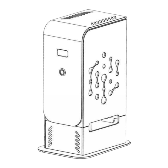
1 4 port USB hub 1 4 port USB hub 2 rear mounting systems 2 rear mounting systems TECHNICALS SPECIFICATIONS Rear mounting systems Air vents OLED display (disabled) On / off button ® Pilot user manual © DOGA | DOC.60514... -
Page 8: Electrical Characteristics
Capacity and connectivity Screwdriving tools Until 20 I/O extension Until 2 Analog Module Until 2 Memory capacity SD card 128 G Number of sequences (3.5 to 5 36 000 Output file (150Ko) 840 000 ® Pilot user manual © DOGA | DOC.60514... -
Page 9: Starting Up
The DPM®Pilot process supervision and traceability controller can be installed on the workstation by 2 ways: 1- Fixed on a stud thanks to the 2 fixing tabs provided. 2- Placed on a shelf or worktop using the support foot. ® Pilot user manual © DOGA | DOC.60514... -
Page 10: Ethernet Ports With Poe Power
Connection of tightening tools Connecting the Digilink module for the positioning arms BS5C Modbus Bit Box Connection Connection of digital input/output add-on module • A network for "WAN" data Linking DPM®Pilot to the corporate network ® Pilot user manual © DOGA | DOC.60514... -
Page 11: Commissioning
If using the stand, place the USB hub inside and secure it using the double-sided adhesive present. COMMISSIONING Press the commissioning button on the front panel (rep. 4). Once the boot is complete, the following screen appears. ® Pilot user manual © DOGA | DOC.60514... - Page 12 On the 1st provisioning and before registering other users, the " " login gives access to administrator privileges. Warning We recommend that you create a new user with administrator privileges via the general "user management" setting and keep the identification code safe. ® Pilot user manual © DOGA | DOC.60514...
-
Page 13: Configuration Settings
This setting is only a one-time setting and should only be changed when you add or remove tools or users, or change regional preferences (date, time, language, etc.). CONFIGURATION SETUP The general settings can be accessed from the main screen. You must be logged in with Administrator privileges. By clicking on the pictogram ® Pilot user manual © DOGA | DOC.60514... - Page 14 Access to Setting Location and Language Preferences Access to the report template and their customization Access to printer settings (login) Access to control mask settings (use a barcode to start a sequence) ® Pilot user manual © DOGA | DOC.60514...
-
Page 15: General Setup Form
Alert threshold for the sequence execution time indicator expressed in % Beyond this threshold, the execution time changes to orange. Once the time is over, it turns red. The execution time of the sequence is set in the sequence ® Pilot user manual © DOGA | DOC.60514... -
Page 16: Network Settings Screen
100% local application. Click the The following screen appears: Designation network Network to be configured (external WAN or LAN) IP address on the network Automatic Addressing (DHCP) Mode ONLY for WAN Subnet mask Gateway ® Pilot user manual © DOGA | DOC.60514... -
Page 17: Workstation" Configuration Screen
Display area of the connections of the tools to the device In these connections we set the physical links made (depending on the tool) Tool display area (screwdriver, arm bit box, etc.) ® Pilot user manual © DOGA | DOC.60514... - Page 18 The following screen appears: Designation Selection area of the tool or accessory to be connected • Select the equipment you want to add: An icon appears. • Click the icon to add the selected equipment. ® Pilot user manual © DOGA | DOC.60514...
- Page 19 Most equipment or tools are used with one or more elements dedicated to them (e.g. screwdrivers, etc.) To add one or more items: • Select Equipment icons appear and the list of compatible items appears in the right banner of the screen. ® Pilot user manual © DOGA | DOC.60514...
- Page 20 To add an item related to the item, select the item you want from the right banner and then click on the icon place it on the item. ® Pilot user manual © DOGA | DOC.60514...
- Page 21 For the BS-5C bit box connected via Modbus with DPM®Pilot, a "BS-5C virtual" device connected to DPM®Pilot must be added to the configuration. The IP address set in the BS-5C Tip Box must be specified in the "IP address" parameter of the "BS-5C Virtual". ® Pilot user manual © DOGA | DOC.60514...
-
Page 22: Folders" Configuration Screen
This menu is used to set the location of the folders containing the sequences, reports, results databases, images used when editing the sequences, when they are not stored in DPM®Pilot's internal memory. Click the The following screen appears: Designation Visualizing the location of elements ® Pilot user manual © DOGA | DOC.60514... - Page 23 Content to be recorded (sequence, results, PV template, media) Location (external drive, or network slot) ➢ Name the alias (name of your folder) ➢ Select content. ➢ Select Location ➢ Tap the icon to validate. ® Pilot user manual © DOGA | DOC.60514...
-
Page 24: Users" Configuration Screen
This menu is used to set up the authorized users by assigning them a role and saving their credentials. Click the The following screen appears: Designation Contextual help List of Declared Users Menu bar to access the different configuration pages Icons for adding/editing/removing a user ® Pilot user manual © DOGA | DOC.60514... - Page 25 Name given to the user Login password Content of the badge for the use of a compatible RFID badge reader User Privilege Assigned Administrator Methods Controller Expert Operator Operator Maintenance Validity Not use ® Pilot user manual © DOGA | DOC.60514...
- Page 26 ✓ ✓ ✓ ✓ ✓ Access to the exit button Access to all ✓ functions ✓ Accessible or permitted Inaccessible or prohibited ® Pilot user manual © DOGA | DOC.60514...
-
Page 27: Regional Settings" Screen
3.1.6 "Regional settings" screen This menu is used to set the language of use, date and time, and geographical preferences. ® Pilot user manual © DOGA | DOC.60514... -
Page 28: Report Template" Screen
This menu is used to add or remove report templates and to set up the report's customizable fields (address, logo). The choice of the model to be used is made at the level of the sequence configuration. ® Pilot user manual © DOGA | DOC.60514... -
Page 29: Printers" Screen
The printer's dimension and resolution settings appear. To declare and set up an unseen network printer. • Click the icon in field 2. • Set the name, network address, and print port. ® Pilot user manual © DOGA | DOC.60514... -
Page 30: Barcode" Screen
AAA000 ▪ To validate that the entry is composed of 3 characters, letters, numbers, special characters strictly, you must enter in the field under string of characters: ??? ® Pilot user manual © DOGA | DOC.60514... - Page 31 Field 2: This field is used to set up a validator on the identifier used to launch a sequence. If the barcode used contains other characters in addition to the sequence ID, it is also possible to truncate unnecessary characters when the sequence is started. ® Pilot user manual © DOGA | DOC.60514...
-
Page 32: Sequence Editing
To access the Sequence Editor: • Select the "Sequence Editor" tile Or use the %JOB_MANAGER barcode. To return to the main screen: • Tap outside the editor window or use the %MAIN_SCREEN barcode ® Pilot user manual © DOGA | DOC.60514... -
Page 33: Managing The Indices And Statuses Of A Sequence
D: inactive An operator user will only have access to valid sequences in the operation menu (sequence execution). Sequences with the status "Test" will only be accessible to a "Methods" or "Administrator" user. ® Pilot user manual © DOGA | DOC.60514... -
Page 34: Creating A Sequence
Banner with possible steps Banner with the editing tools for the sequence The sequence construction window. List of variables that are used in the sequence in user input, button, extract, and referral steps ® Pilot user manual © DOGA | DOC.60514... -
Page 35: External Data Recovery Step
External Data Recovery Step • For example, to retrieve the screwdriving job number to be used ® Pilot user manual © DOGA | DOC.60514... -
Page 36: Deletes The Selected Step
4.2.5 Deleting an existing step Select the step you want to edit: • Select the step (an outline appears). • Select the Editing Tool Information Please note that the deletion is permanent. ® Pilot user manual © DOGA | DOC.60514... -
Page 37: Adding An Action In The Step
Change the setting(s) you want. 4.2.8 Deleting an existing action • Select the action (it appears in a blue frame) • Tap the icon Information Please note that the deletion is permanent. ® Pilot user manual © DOGA | DOC.60514... -
Page 38: Recording A Sequence
Information The sequence file is a pack containing the steps, media, and positioning points. The generation of the complete file containing all the information is done when the edit menu is exited. ® Pilot user manual © DOGA | DOC.60514... -
Page 39: Multimedia
Media type selection area (text/visual instruction (image or PDF import Dynamic display viewing area Validation and Backup Icon Information For the screwing steps, the visual media set up in window 1 will be the support for the screwing point identification chips. ® Pilot user manual © DOGA | DOC.60514... -
Page 40: The Tightening Step
The declaration and configuration of the tools is done from the configuration menu; If there is no bit or socket selection check required, leave blank Action settings area contained in the step ® Pilot user manual © DOGA | DOC.60514... - Page 41 Field 9 If you want to make tightening conditional on the use of a bit, specify a tool. If no tools are selected, the screwing will be done without control of the use of the bit. • Field 10. Add the actions. To do this, click ® Pilot user manual © DOGA | DOC.60514...
- Page 42 NOK. If a rework number is specified, a field appears to indicate which tightening program to use. This makes it possible, for example, to have different angular limits if the rework changes the assembly characteristics, or an angular counting threshold that is different from the initial program. ® Pilot user manual © DOGA | DOC.60514...
- Page 43 Or with the mouse while holding down the right button. ▪ Or with the arrows on the keyboard. Sample image ✓ • To finish the configuration and access the next page, click on at the top right. ® Pilot user manual © DOGA | DOC.60514...
- Page 44 The saved tolerance will be a rectangle around the point. ✓ • Click the button to save. Information Each position control point must have a unique number. Remember to specify a different number for each screwing point. ® Pilot user manual © DOGA | DOC.60514...
- Page 45 4.2.11.3 Example of setting up a stage The identifier for this step is: tightening 1 Name: The screwdriver used is: Doga MDTC Tightening Tool 01 The position control device used is: Doga Arm tool 01 The socket/bit box used is: Bit Socket tray Toll 01 An action is set up: •...
-
Page 46: Pick To Light Stage (Component Socket Control)
Select the icon with the mouse or on the touchscreen • Place the step in the branch of the sequence where you want it (drag and drop action). • Select the step (an outline appears). • Select the Editing Tool ® Pilot user manual © DOGA | DOC.60514... - Page 47 Field designating the part number or part designation that will appear on the execution screen Field specifying the minimum activation time of the sensor integrated in the LED to validate the component's socket Field specifying the number of takes to complete to validate the step ® Pilot user manual © DOGA | DOC.60514...
- Page 48 This will correspond to the number of sensor activations to be recorded. Information Under no circumstances does activating the sensor guarantee that the component will be plugged. The pick to light is an aid device and not a control device. ® Pilot user manual © DOGA | DOC.60514...
-
Page 49: Stage Of Checking The Status Of The Digital Inputs
• Place the step in the branch of the sequence where you want it (drag and drop action). • Select the step (an outline appears). • Select the Editing Tool ® Pilot user manual © DOGA | DOC.60514... - Page 50 Media settings and layout field (see multimedia section) A field that specifies the input-output tool used for the step A field designating the entry(s) to be checked and the expected state to validate the step. ® Pilot user manual © DOGA | DOC.60514...
- Page 51 Repeat the operation for each of the entries to be tested in the step. To remove control from an entry: • Select the action (it appears in a blue frame). • Click the icon ® Pilot user manual © DOGA | DOC.60514...
- Page 52 Information Please note that the deletion is permanent. To edit an action: • Select the action (it appears in a blue frame) • Select the Editing Tool • Change the desired setting(s) ® Pilot user manual © DOGA | DOC.60514...
-
Page 53: Stage Of Tor Output Activation
• Place the step in the branch of the sequence where you want it (drag and drop action). • Select the step (an outline appears). • Select the editing tool ® Pilot user manual © DOGA | DOC.60514... - Page 54 A field to specify a time during which the step remains active during execution. This time is not related to the time set for impulse activation or flashing The field designating the outputs to be ordered. ® Pilot user manual © DOGA | DOC.60514...
- Page 55 Repeat the operation for each of the outings to be ordered in the step. To remove the command from an output: • Select the action (it appears in a blue frame). • Tap the icon Information Please note that the deletion is permanent. ® Pilot user manual © DOGA | DOC.60514...
- Page 56 To edit an action: • Select the action (it appears in a blue frame). • Select the editing tool • Change the setting(s) you want. ® Pilot user manual © DOGA | DOC.60514...
-
Page 57: Step To Record A Value From An Analog Input
Place the step in the branch of the sequence where you want it (drag and drop action). • Select the step (an outline appears). • Select the editing tool • When the raw value is selected (the default), the following setup screen appears: ® Pilot user manual © DOGA | DOC.60514... - Page 58 Limit values can be saved by learning by clicking the learn button A field to specify the variable that will contain the recorded analog value ® Pilot user manual © DOGA | DOC.60514...
- Page 59 • Field 11 Specify the variable in which the value will be stored. This variable may be used in one or more forward referral or message steps. ® Pilot user manual © DOGA | DOC.60514...
-
Page 60: Photo Taking Step For Incorporation Into The Results Report
Place the step in the branch of the sequence where you want it (drag and drop action). • Select the step (an outline appears) • Select the editing tool The settings screen below appears: ® Pilot user manual © DOGA | DOC.60514... - Page 61 A self-explanatory name makes it easy to know what the step does. • Field 5 Setting up media and their layout (see paragraph "Multimedia"). • Field 6 Click on the "Photo Settings" button. ® Pilot user manual © DOGA | DOC.60514...
- Page 62 • The screen below appears: • You can adjust your camera settings and its position. Validate button. Refresh button. ® Pilot user manual © DOGA | DOC.60514...
-
Page 63: In-Sequence Label Printing Step
The printer is chosen from the general configuration menu of DPM®Pilot. Information The main printing system under Ubuntu is the Common UNIX Printing System (CUPS). This printing system has become the new standard for printing in most Linux distributions. ® Pilot user manual © DOGA | DOC.60514... - Page 64 Viewing the sequence being edited Step ID field REQUIRED FIELD Step name field REQUIRED FIELD Pixel label dimension field and printer choice Label information addition field Dynamic view of the layout and label content ® Pilot user manual © DOGA | DOC.60514...
- Page 65 Type of field to print (text / image / barcode / QR code) Field length Field height Start position on X (horizontal axis) Starting position on Y (vertical axis) Dynamic view of the label being edited Field 2 Choose the type of information: ® Pilot user manual © DOGA | DOC.60514...
- Page 66 Give it a name. • Select the image you want to print. The selected image appears in the Smart Viewport. • Specify the length and height of the field. • Specify the starting position. ® Pilot user manual © DOGA | DOC.60514...
- Page 67 Please note that the deletion is permanent. To edit an action: • Select the field and edit the content. At the end of the edit, it is possible to start a print by pressing the icon ® Pilot user manual © DOGA | DOC.60514...
-
Page 68: Start Polling Step Of One Or More Tor Inputs
Place the step in the branch of the sequence where you want it (drag and drop action). • Select the step (an outline appears). • Select the Editing Tool • The settings screen below appears: ® Pilot user manual © DOGA | DOC.60514... - Page 69 Field 6 Select the input tool to use. • Field 7 Specify the combinatorial operator to apply to the inputs. • Field 8 Specify the entries to be scanned. ▪ The following screen appears: ® Pilot user manual © DOGA | DOC.60514...
- Page 70 Information Please note that the deletion is permanent. To edit an action: • Select the action (it appears in a blue frame). • Select the editing tool Change the setting(s) you want. ® Pilot user manual © DOGA | DOC.60514...
-
Page 71: End Of Polling Step For One Or More Tor Entries
The settings screen below appears: Designation Condition Command saves or exit Viewing the sequence being edited Step ID field REQUIRED FIELD Step name field REQUIRED FIELD A field that specifies the polling start step ® Pilot user manual © DOGA | DOC.60514... -
Page 72: Operator Information Entry Step
Place the step in the branch of the sequence where you want it (drag and drop action). • Select the step (an outline appears). • Select the editing tool • The settings screen below appears: ® Pilot user manual © DOGA | DOC.60514... - Page 73 Screen if there is no validator. Display with digital validator. ® Pilot user manual © DOGA | DOC.60514...
- Page 74 A field specific to the alphanumeric validator that will appear if the alphanumeric validator is selected in field 6. This field will be used to specify which condition will be controlled on what will be entered by the user ® Pilot user manual © DOGA | DOC.60514...
- Page 75 No → consistency check, the value or the scanned code is recorded in the variable defined in field 7. Numerical → Consistency checks with validator adapted to the processing of a numerical value (number). ® Pilot user manual © DOGA | DOC.60514...
- Page 76 Field 5 Fill in the instruction field to tell the operator what to do in this step. "Measure the length of the workpiece with the ruler and type it on the keyboard ." ® Pilot user manual © DOGA | DOC.60514...
- Page 77 200. If the value entered is between these 2 values, the entry is validated. If the value is not within range, the message "Error" appears. Example numeric value screen ® Pilot user manual © DOGA | DOC.60514...
- Page 78 The name must be self-explanatory enough to allow you to understand unequivocally what the variable will contain as a type of information, e.g.: Measurement lg, Diversity1 ... ® Pilot user manual © DOGA | DOC.60514...
- Page 79 AAA000 ▪ To validate that the entry is composed of 3 characters, letters, numbers, special characters strictly, you must enter in the field under string of characters: ® Pilot user manual © DOGA | DOC.60514...
- Page 80 For example, the set of words "ex-équo, ex-equo, ex-aequo and ex-æquo" can be condensed into a single reason "ex-(a?e|æ|é)quo". The basic mechanisms for forming such expressions are based on special characters of substitution, grouping, and quantization. ® Pilot user manual © DOGA | DOC.60514...
- Page 81 Field 9 In this field you specify the logical operator applied to the validators specified in field 10: the logical operator And is used. • Field 10 In this field we use the "contains" validator with 2 actions: Action 1 contains abcde Action 2 contains 12345 ® Pilot user manual © DOGA | DOC.60514...
- Page 82 ® Pilot user manual © DOGA | DOC.60514...
-
Page 83: Selection Step By Virtual Button On The Screen
Place the step in the branch of the sequence where you want it (drag and drop action). • Select the step (an outline appears). • Select the Editing Tool • The settings screen below appears: ® Pilot user manual © DOGA | DOC.60514... - Page 84 The text or content of the button selected by the user when the sequence is executed is saved in the variable specified in field 7. Information The number of buttons must be limited to 6. ® Pilot user manual © DOGA | DOC.60514...
- Page 85 Field 7 We use the button1 variable that we added beforehand. • Field 8 Create 3 buttons by pressing the icon Button 1 → option 1 Button 2 → option 2 Button 3 → option 3 ® Pilot user manual © DOGA | DOC.60514...
- Page 86 ® Pilot user manual © DOGA | DOC.60514...
- Page 87 Step screen after setup. ® Pilot user manual © DOGA | DOC.60514...
-
Page 88: Message Step
(internal memory or USB stick) The field for setting the amount of time before the button is active. The time setup field before the step is automatically validated. ® Pilot user manual © DOGA | DOC.60514... - Page 89 Field 7 To be filled in if you want the validation button to be active (in blue) after a time (expressed in seconds). • Field 8 To be filled in if you want the message step to be validated automatically after a time (expressed in seconds). ® Pilot user manual © DOGA | DOC.60514...
-
Page 90: Variable Value Extraction Step
Place the step in the branch of the sequence where you want it (drag and drop action). • Select the step (an outline appears). • Select the Editing Tool • The settings screen below appears: ® Pilot user manual © DOGA | DOC.60514... - Page 91 Character 3 Character 4 Character 5 Character 6 Character 7 Multiple combinations can be extracted from the same source content in a single step. Each extraction is saved in a specific variable. ® Pilot user manual © DOGA | DOC.60514...
- Page 92 A print step will need to be placed downstream of the pull step to print. • Field 3 Indicate the identifier: Extractionpump • Field 4 Indicate the name of the step: Extraction Pump Reference • Field 5 Specify the name of the source variable: barcodepump ® Pilot user manual © DOGA | DOC.60514...
- Page 93 Car 5 Car 6 Car 7 Car 8 Car 9 Car 11 Car13 • Field 7 We indicate the destination variable of the 2nd extraction SNpompe and the characters to be extracted from ® Pilot user manual © DOGA | DOC.60514...
- Page 94 Extraction example screen ® Pilot user manual © DOGA | DOC.60514...
-
Page 95: Switch Step
Place the step in the branch of the sequence where you want it (drag and drop action). • Select the step (an outline appears). • Select the editing tool • The settings screen below appears: ® Pilot user manual © DOGA | DOC.60514... - Page 96 • Field 5 Specify the name of the variable whose content is to be analysed. • Field 6 Specify the conditions to apply to the content of the variable (numeric or alphanumeric). ® Pilot user manual © DOGA | DOC.60514...
- Page 97 Select the carrier you want to apply. • Enter the target value in field 8.1 "Value". • Select the destination that will be reached if the test is OK in field 8.2. ® Pilot user manual © DOGA | DOC.60514...
- Page 98 Beforehand, it is necessary to create the sub-branches containing the steps towards which the switch will direct the sequence. • To create a subbranch: Tap the icon on the screen showing the sequence diagram. ® Pilot user manual © DOGA | DOC.60514...
- Page 99 A self-explanatory name makes it easy to know what the step does. • Field 5 Specify the name of the variable whose content will be analysed. • Specify the conditions to apply to the content of the variable (numeric or alphanumeric). ® Pilot user manual © DOGA | DOC.60514...
- Page 100 ® Pilot user manual © DOGA | DOC.60514...
- Page 101 Enter the target value in field 8.1 "Value". • Select the destination that will be reached if the test is OK in field 8.2. If the numerical condition was chosen in field 6: • The screen below appears: ® Pilot user manual © DOGA | DOC.60514...
- Page 102 Labelprint 26 The sequence is as follows: Operator information entry step Referral step Destination step if input is AAAY Destination step if the input is BBBB ® Pilot user manual © DOGA | DOC.60514...
- Page 103 If the variable • If CB contains AAAA, the switch will direct the sequence to the downstream step Message 4 • If the CB variable contains BBBB, the turnout will direct the sequence to the downstream Labelprint 26 step ® Pilot user manual © DOGA | DOC.60514...
- Page 104 Once the configuration was made, the synoptic diagram evolved as follows: • Arrows connect the switch to the destinations. ® Pilot user manual © DOGA | DOC.60514...
- Page 105 At the end of the execution of the subbranch, the return is made to the END step of the main branch. We start by creating the 3 sub-branches: Then we set the content of the 3 sub-branches. For the example, we incorporate a message step. ® Pilot user manual © DOGA | DOC.60514...
- Page 106 Once the sub-branch settings have been completed, the switching step is placed in the main branch. You select the switching step to set it up (by pressing the icon ® Pilot user manual © DOGA | DOC.60514...
- Page 107 If the button variable contains "choice 1", the switch will direct the sequence to the Sub in 28 subbranch. • If the button variable contains "choice 2", the switch will direct the sequence to the Sub in 29 subbranch. ® Pilot user manual © DOGA | DOC.60514...
- Page 108 If the button variable contains "choice 3", the switch will direct the sequence to the Sub in 30 subbranch. Once the configuration was made, the synoptic evolved as follows: • Arrows connect the switch to the destinations. ® Pilot user manual © DOGA | DOC.60514...
- Page 109 Select the Sub out 28 step, and then select the edit icon • Select the END destination. Once the configuration was made, the synoptic evolved as follows: • An arrow connects the subbranch end step to the END destination. ® Pilot user manual © DOGA | DOC.60514...
- Page 110 Select the Sub out 29 step, and then select the edit icon • Select the END destination. Once the configuration was made, the synoptic diagram evolved as follows: • An arrow connects the end step of the subbranches to the END destination. ® Pilot user manual © DOGA | DOC.60514...
- Page 111 Select the Sub out 30 step, and then select the Edit icon • Select the END destination. Once the configuration was made, the synoptic diagram evolved as follows: • An arrow connects the end step of the subbranches to the END destination. ® Pilot user manual © DOGA | DOC.60514...
- Page 112 For better readability, it is possible to place the sub-branches higher or lower in the sequence graph using the keys ® Pilot user manual © DOGA | DOC.60514...
- Page 113 When executing the sequence: • For example, if the user selects "choice 1" in the button step, the sequence will proceed as follows: ® Pilot user manual © DOGA | DOC.60514...
- Page 114 The other 2 sub-branches will not be unrolled. ® Pilot user manual © DOGA | DOC.60514...
-
Page 115: Working With External Data Step
A field to specify the variable that will contain the extracted data Field for setting up links between the location of the data and its correspondence with the expected parameters ® Pilot user manual © DOGA | DOC.60514... - Page 116 No. of the tightening program to be used bitid Identifier of the bit to be used retries Number of tests possible in case of NOK tightening retryProg No. of the assembly program to be used for repeat tightening ® Pilot user manual © DOGA | DOC.60514...
-
Page 117: Tightening Step With External Data
Field designating the number of points to be made in the step ® Pilot user manual © DOGA | DOC.60514... - Page 118 • Field 9. Select the variable that contains the parameters you want to use. • Field 10 Indicate the number of points. ® Pilot user manual © DOGA | DOC.60514...
-
Page 119: Production
To access the sequence execution in production, you must select the "Production" tile or use the barcode %OPERATION To return to the main screen: • Tap outside the editor window or use the %MAIN_SCREEN barcode. ® Pilot user manual © DOGA | DOC.60514... - Page 120 A user with operator privileges will only have access to sequences with a status of "Validated". A sequence with a status of "validated" is recognizable by the presence of the letter V at the end of the display name. ® Pilot user manual © DOGA | DOC.60514...
-
Page 121: Start A Sequence
It is possible to filter certain characters contained in a barcode via the settings available in the configuration menu to take into account only the characters necessary to identify the sequence to be launched. By selecting a sequence from the list in field 2. ® Pilot user manual © DOGA | DOC.60514... - Page 122 If the sequence selection needs to be changed, you must return to the previous menu. To do this, there are two possible choices: Click the screen outside the selection window. Scan a barcode with the text %STOP. ® Pilot user manual © DOGA | DOC.60514...
- Page 123 Field containing actions in the current step Field the status of the tools used in the current step A field containing the media(s) specified when editing for the stage. User ID Connected tool ® Pilot user manual © DOGA | DOC.60514...
- Page 124 It is possible to filter certain characters contained in a barcode via the settings available in the configuration menu to take into account only the characters necessary to identify the sequence to be launched. By selecting a sequence from the list in field 2. ® Pilot user manual © DOGA | DOC.60514...
- Page 125 Reset Select to redo the sequence from the beginning. The results previously saved for the serial number will be deleted. The serial number entered is reused. ® Pilot user manual © DOGA | DOC.60514...
- Page 126 The sequence is recorded as in progress in the results. • The part identified by its serial number is in the current parts list. • The assembly of the part can be restarted (continue or reset). ® Pilot user manual © DOGA | DOC.60514...
-
Page 127: Rework
6 REWORK Information Access to this menu from the main screen is accessible only to users with the privilege to edit a part. UNDER DEVELOPMENT ® Pilot user manual © DOGA | DOC.60514... -
Page 128: Results
To access the results minutes, you must select the "Results" tile. or use the %RESULTS barcode To return to the main screen: • Tap outside the edit window or use the %barcode MAIN_SCREEN ® Pilot user manual © DOGA | DOC.60514... -
Page 129: Consultation Of A Report Of Results
CONSULTATION OF A REPORT OF RESULTS • Enter the PV number you want to view in field 1 or select it from drop-down list 2. • Tap "View." • The selected ticket appears on the screen. ® Pilot user manual © DOGA | DOC.60514... -
Page 130: Printing Of A Report Of Results
PRINTING OF A REPORT OF RESULTS UNDER DEVELOPMENT ® Pilot user manual © DOGA | DOC.60514... -
Page 131: Maintenance
Main screen view To access the results minutes, select the "Maintenance" tile. or use the %MAINTENANCE barcode To return to the main screen: • Tap outside the editor window or use the %MAIN_SCREEN barcode ® Pilot user manual © DOGA | DOC.60514... -
Page 132: Test The Different Tools And Equipment Connected To The Workstation Menu
The possible actions and test functions depend on the tool. To test a connected tool: • Select the tool in the tree view. Testable functions or available information appear in the window on the right side of the screen. Examples: ® Pilot user manual © DOGA | DOC.60514... - Page 133 ® Pilot user manual © DOGA | DOC.60514...
-
Page 134: Backup
• Results database • Media (images and PDFs used to set up visuals in sequences) It is also possible to delete items via the Delete menu. Warning WARNING! ANY DELETION IS FINAL. ® Pilot user manual © DOGA | DOC.60514... -
Page 135: Testing Connected Peripheral Devices
8.1.3 Testing connected peripheral devices. In this menu, it is possible to test the proper functioning of the input or printing devices. ® Pilot user manual © DOGA | DOC.60514... -
Page 136: Backup And Charging Via Usb Stick
Plug the key into DPM®Pilot. • Carry out the commissioning: The sequence files are saved. The application launches. • Remove the USB drive • Back up the file to a durable backup source. ® Pilot user manual © DOGA | DOC.60514... -
Page 137: Upload The Sequence File To Dpm®Pilot
Plug the key into DPM®Pilot. • Carry out the commissioning: The sequence files are saved. The application launches. • Remove the USB flash drive. • Back up the file to a durable backup source. ® Pilot user manual © DOGA | DOC.60514... -
Page 138: Maintenance
Contact DOGA After-Sales Service work perfectly. If you cannot solve an issue after reviewing this manual, please contact DOGA After-Sales Service. My customer area on www.doga.fr Go to your customer area on www.doga.fr, click on "Your contacts"... -
Page 139: Phone Support
8.6.1.1 Please contact your technical sales representative. My customer area on www.doga.fr Go to your customer area on www.doga.fr, click on "Your contacts" and then select your specific Technical Sales Representative depending on the device type. For any questions about repairs 8.6.1.2... -
Page 140: After-Sales Returns
8.7.1.2 The returned package must be postage paid to the following addresses depending your transport mode: Postal packages Carrier packages DOGA - Service SAV DOGA - Service SAV 8, avenue Gutenberg - CS 50510 11, rue Lavoisier 78317 Maurepas Cedex... -
Page 141: On-Site Repair
Our services will organize the intervention. WARRANTY DOGA guarantees its products against defect in parts or fabrication for a period of 12 months. To benefit from the parts and labour warranty, the following conditions must be respected: The equipment must have been used for professional manner and in accordance with normal conditions of use in ⚫... -
Page 142: Security
In each case, respect and comply with national safety standards. Do not remove or damage labels and annotations affixed to the product, especially those required by law. CONTRA-INDICATIONS Do not cover. Do not submerge. Do not expose to splashing liquids. Do not use near a heat source. ® Pilot user manual © DOGA | DOC.60514... -
Page 143: Standard
Clean the product according to the instructions in the Maintenance chapter. ⚫ Store it in a suitable container to protect it from dust and direct sunlight. ⚫ Store it in a dry place at an ambient temperature below 40°C. ® Pilot user manual © DOGA | DOC.60514... -
Page 144: Recycling And End-Of-Life Of Weee
In accordance with the provisions of the Environmental Code on Waste Electrical and Electronic Equipment (WEEE) (art. R543-195 et seq.), DOGA is a member of ECOSYSTEM, an eco-organisation approved by the public authorities under the conditions defined by art. R543-197. -
Page 145: Annexes
12.1 DESCRIPTION OF THE WURTH ELEKTRONIK CONNECTOR 691381000012 DIGITAL INPUTS AND OUTPUTS Designation Input1 Input 2 Input 3 Input 4 Exit 1 Exit 2 Exit 3 Exit 4 Common for inputs Common for output 24 Vdc Mass ® Pilot user manual © DOGA | DOC.60514... - Page 146 Example of wiring ® Pilot user manual © DOGA | DOC.60514...
-
Page 147: Mass
12.2 MASS Designation Input 1 Input 2 Common for inputs Exit 1 Exit 2 Common for outputs 24 Vdc Mass ® Pilot user manual © DOGA | DOC.60514... -
Page 148: Example Of Wiring
Example of wiring ® Pilot user manual © DOGA | DOC.60514... -
Page 149: Description Of Dpm®Wiring Module
The cables are routed through the cable grommet to be drilled. It is possible to use an external power supply on the outputs. The switch is switched by positioning the S1 switch in the corresponding position. ® Pilot user manual © DOGA | DOC.60514... -
Page 150: Description Of The Dpm®I/O Module
The cables are routed through the cable grommet to be drilled. It is possible to use an external power supply on the outputs. The switch is switched by positioning the S1 switch in the corresponding position. ® Pilot user manual © DOGA | DOC.60514... -
Page 151: Back To The Sequence Selection Menu
Selecting the result menu from the main window Selecting the maintenance menu from the main window Validation in a message step Start the previously selected sequence Back to the sequence selection menu ® Pilot user manual © DOGA | DOC.60514... -
Page 152: Launch Barcodes And Selection
Setting up the barcode scanner is done in 4 steps: 1. Initializing the default settings: scan the code below. 2. Enter key CR/LF 3. Configuration en USB Simple COM Port Emulation 4. Configuration USB-CDC Host ® Pilot user manual © DOGA | DOC.60514... - Page 153 12.6.1.2 Setting the Model DS3608 Barcode Scanner Setting up the barcode scanner is done in 2 steps: ® Pilot user manual © DOGA | DOC.60514...
-
Page 154: Setting Up The Cvi3 Dessouter Tightening Controller
12.7 SETTING UP THE CVI3 DESSOUTER TIGHTENING CONTROLLER Set up the cycle call as follows: • "Assembly Unit" Menu • Mode of operation: "Cycle" • Source cycle: "Open Protocol». ® Pilot user manual © DOGA | DOC.60514... -
Page 155: List Of Revisions
13 LIST OF REVISIONS Revision index Date Comment 12/07/2024 Creation ® Pilot user manual © DOGA | DOC.60514... - Page 156 ® Pilot user manual © DOGA | DOC.60514...
- Page 157 © DOGA | DOC.60514-07/2024...
Need help?
Do you have a question about the DPM Pilot Standard and is the answer not in the manual?
Questions and answers