Table of Contents
Advertisement
Advertisement
Table of Contents

Related Manuals for DOGA DPC Touch


Summary of Contents for DOGA DPC Touch
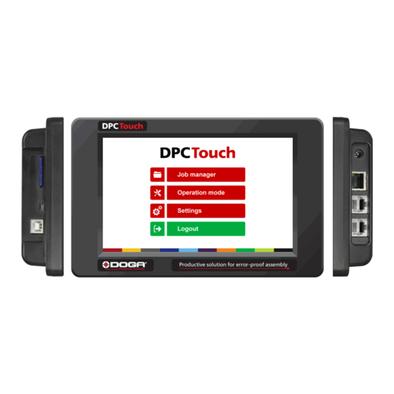
- Page 1 DPC Touch INSTRUCTIONS MANUAL...
- Page 2 DPC Touch User Manual IMPORTANT The controller delivered with this manual may be modified for specific needs. In this case, please give us the controller serial number written on our shipping note or the approximate controller delivery date when you will place an order for a new similar controller or for spare parts.
-
Page 3: Table Of Contents
Inputs wiring scheme ......................25 Outputs wiring scheme ......................26 Connection of DOGA low voltage tools GX/GY/DO/GA ............27 Connection of DOGA Hybrid HDC and Current control SDC tools ......... 28 Connection of DOGA current control MDC Series……………………………………………………………..27 Connection of ATLAS PF4000…………………………………………………………………………………………….28 Connection of Stanley Alpha and Kappa tools .............. -
Page 4: Specifications
DPC Touch User Manual 1. SPECIFICATIONS Specification DC24V, 1A 1. Input power AC 100-240V / DC 24V adaptor is provided 2. Dimensions 202(W) x 128(H) x 38(D) mm 3. Weight 0.55 kg 4. Screen 7” LCD Touch screen, 800 x 480 px 5. -
Page 5: Hardware
DPC Touch User Manual 2. HARDWARE Dimensions and mounting interface Mounting plate with 4 x M3 screws is delivered with the controller as a standard accessory. Weight of the controller: 0.55 kg... -
Page 6: Interface Ports
(see Electric wiring chapter for Encoders port adaptor is used to connect standard the wiring scheme). DOGA positioning arms to DPC Touch. ATTENTION: Do not connect positioning arm directly to DPC Touch (serial numbers starting with SC*******)! This may damage encoders! -
Page 7: Getting Started
DPC Touch User Manual 3. GETTING STARTED 1. Connect power supply to the controller to turn it on. Normal booting time is about 2 sec. If controller is not booted, the last booting step indicates the problem (e.g. Init SD Card… - missing or damaged SD card). -
Page 8: Job Manager
DPC Touch User Manual 5. JOB MANAGER Job manager interface provides access to the list of saved jobs. It also allows to Edit or to Delete saved jobs as well as to create new ones by pressing New button or by Copying an existing job. -
Page 9: New Job Creation
DPC Touch User Manual 6. NEW JOB CREATION While in Job Manager screen, press NEW button. New job will be created and placed in the end of the list. New job creation screen will be displayed automatically. A job is represented by a sequence of steps. These steps can be organized in any order which corresponds to the desired production sequence. -
Page 10: Fastening Step Creation
DPC Touch User Manual Fastening step creation NOTE: it is useful to define encoder’s reference point before creating a fastening step. See encoder’s settings for more information. While in Job creation screen, tap on FASTENING step button. The Fastening step creation screen will appear. -
Page 11: Manual Programming Of Fastening Step
(outside position OK zone) in order to pick up a screw. Fastening OK signals and Motor run signals are not effective on pick-up position. Driver 1 and 2 selection is only applied to DOGA tools (GX, GY, DO, GA) connected through RJ45 port. This selection allows enabling and disabling tools for each individual position. -
Page 12: Automatic Programming Of Fastening Step
DPC Touch User Manual 6.1.2 Automatic programming of fastening step: For automatic programming, make sure that the tool is connected to the controller and signals are correctly assigned. In order to register tightening time, Motor run and Fastening OK signals have to be connected. -
Page 13: Logical Input Step Creation
DPC Touch User Manual Logical Input step creation While in Job modification screen, tap on LOGICAL IN button. The Logical In step creation screen will appear. Select an available input from the list of Inputs. If an Input was assigned for a specific function in Input settings it is not available to be used as a logical signal. -
Page 14: Message Step Creation
DPC Touch User Manual Message step creation While in Job modification screen, tap on MESSAGE button. The message step creation screen will appear. Enter the text to be displayed and activate the corresponding switch. Select an image to be displayed from the list of available images and activate the corresponding switch. -
Page 15: Job Example
DPC Touch User Manual Job example A simple job may contain only a Fastening step, which will assure screws counting and tool position control functions. Example below illustrates a job for management of an automated station with multiple sensors and actuators. -
Page 16: Settings
(one input per job). Default job is a job which is automatically started after Default job booting of DPC Touch. If default job number is set to 0, 0 - 999 number DPC Touch will not boot any jobs. - Page 17 DPC Touch User Manual Screen 3 of 4: Management of fastening time Lower limit of fastening time control in percentage of Min fastening actual fastening time detected during programming. 0 - 100 time limit, % NOTE: changes will be applied only to new jobs, existing jobs won’t be affected.
-
Page 18: Encoders
DPC Touch User Manual Encoders Encoder’s activation and tolerance settings (screen 1 of 2) Activate or deactivate corresponding encoders by selecting check boxes accordingly. Enter default tolerance values for the approaching Area and for OK zone where tool is enabled. -
Page 19: Inputs
Each input function can be assigned only once. Input name Function description Signal type Inputs to select jobs on DPC Touch in binary or in direct logic Job select 1-8 Continuous (see the table below). Logic is selected in operating settings. -
Page 20: Outputs
DPC Touch User Manual Outputs Activate desired outputs by selecting corresponding check boxes. Select required output type from the list. Non-assigned outputs can be used for Logical Out steps. Duration of impulse signals is 100 ms. Each output function can be assigned to multiple outputs. -
Page 21: Network
DPC Touch User Manual Network Network communication is not enabled in firmware v.0.2.8 Other Real time monitoring of encoders and I/O’s (screen 1 of 4) This interface helps to verify if encoders function correctly. It also helps to check status of input signals and to force output signals to test wiring. -
Page 22: Operating Mode
DPC Touch User Manual 8. OPERATING MODE Controller is started automatically in Operating mode after booting. Default job is loaded automatically (see operating settings). Operating mode is accessible through the main menu and though Job Manager by pressing Load button. -
Page 23: Electrical Wiring
DPC Touch User Manual 9. ELECTRICAL WIRING Encoder’s port wiring scheme Only for serial numbers Function SC********* 5V power supply 5V power supply Channel (1) Channel (1) Channel (2) Channel (2) GND (Ch1, Ch3) GND (Ch1, Ch3) GND (Ch2, Ch4) -
Page 24: Inputs Wiring Scheme
DPC Touch User Manual Inputs wiring scheme... -
Page 25: Outputs Wiring Scheme
DPC Touch User Manual Outputs wiring scheme NOTE: All outputs are optically isolated. Max current capacity is 100mA per output. Total of 500mA. -
Page 26: Connection Of Doga Low Voltage Tools Gx/Gy/Do/Ga
5, 6 Driver Lock input *Controllers XT-30D, XS-38D, XS-40D, XS-35D, XT-35D NOTE: Select GX/GY/DO/GA tool interface in DPC Touch operating settings. The tool is locked by short connecting contacts 5 and 6. ATTENTION! Use only straight RJ45-RJ45 cable (not crossed). -
Page 27: Connection Of Doga Hybrid Hdc And Current Control Sdc Tools
Input 8 D_Motor_Run Motor Run Input 9 Tool Alarm Alarm Input 10 D_Fastening_OK Fastening OK IN_COM 0V DC OUT_COM 24V DC NOTE: Select HDC/SDC tool interface in DPC Touch operating settings. Select PLC (except Start and Reverse) interface on HDC/SDC controller. -
Page 28: Connection Of Doga Current Control Mdc Series
24V DC NOTE: All 8 inputs and 8 outputs of MDC controller are wired to DPC Touch controller. These signals can be used for advanced functions (management of Reset, Reverse, etc). I/O’s numbers are matching. Assign signals on DPC Touch and MDC as above. - Page 29 NOTE: Select DC Tool interface in DPC Touch operating settings Either DB25 or DB9 connectors can be used depending on desired number of I/O’s If DB9 connector is used, then max 3 jobs can be selected on DPC Touch in binary logic by using 2 contacts.
-
Page 30: Connection Of Stanley Alpha And Kappa Tools
NOTE: Select DC tool interface in DPC Touch operating settings. In order to use 24V supply from Stanley controller, short connect pins A and B. In this case DPC Touch will be powered by Stanley controller. Don’t connect DPC Touch to external power in this case. -
Page 31: Connection Of Kolver Edu Series Tools
Com 0V DC OUT_COM Com 0V DC NOTE: Select DC tool interface in DPC Touch operating settings. ATTENTION! Cut the bridges (15)-(35) and (30)-(31) in the DB44 connector of the I/O adaptor in order to disconnect 24V power supply before making the interface. -
Page 32: Two Tools Wiring Example
DPC Touch User Manual 9.11 Two tools wiring example Tool A is connected through DB9 connector Tool B is connected through DB25 connector Input Job select bit 0 Input Job select bit 0 Input Job select bit 1 Input Job select bit 1... -
Page 33: Automation Equipment Wiring Example
DPC Touch User Manual 9.12 Automation equipment wiring example I/O adaptor DB25 DB44 DPC Touch Input 1 Input 2 Push button 1 Input 3 Input 4 Input 5 Input 6 Push button 2 Input 7 Input 8 Input 9 max 100mA Input 10 –... -
Page 34: I/O Port Adaptor (Db44 Db25 + Db9) Wiring Scheme
DPC Touch User Manual 9.13 I/O port adaptor (DB44 DB25 + DB9) wiring scheme DB44 DB25 Example of Touch (male) (female) (female) assigned signals Input 1 Job select 1 Input 2 Job select 2 Input 3 Job select 3 ... -
Page 35: Troubleshooting
DPC Touch User Manual Troubleshooting Problem Solution Controller is not Check the boot log on the screen. Last booting step indicates the problem. booted (black Example: “SD card Init” – SD card is not found. Check if SD card is inserted and booting screen) not damaged.
Need help?
Do you have a question about the DPC Touch and is the answer not in the manual?
Questions and answers