
Related Manuals for DOGA BM Series


Summary of Contents for DOGA BM Series
- Page 1 Instruction manual BM SERIES CONTROLLER ParaMon-Pro X 60391-01/21 www.dogassembly.com 433000-10/19...
-
Page 2: Table Of Contents
CONTENTS Symbols...................................... 5 1. INFORMATION................................6 1.1 IMPORTANT..................................6 1.2 Product reference................................6 1.3 Product description................................6 1.4 Standard packing items..............................7 1.5 Specifications..................................8 1.6 System overview.................................8 1.7 Dimensions and appearances............................9 2. HOME..................................11 2.1 Operator mode.................................. 11 2.2 Administrator mode................................12 3. - Page 3 11. SETTING.................................62 11.1 Operation..................................62 11.2 I/O..................................... 67 11.2.1 Input......................................68 11.2.2 Output......................................69 11.3 Log....................................70 11.4 Barcode - without job & BM integrated scanner......................71 11.5 Network.................................... 73 11.6 Share....................................74 11.7 System..................................... 76 12. SYSTEM................................. 77 12.1 Device info..................................77 12.2 Storage....................................
- Page 4 19. MAINTENANCE..............................115 19.1 Maintenance..................................115 19.2 Troubleshooting................................115 19.3 Spare parts..................................116 19.4 Hotline.................................... 116 19.4.1 For any questions about the use of the device........................116 19.4.2 For any questions regarding troubleshooting........................116 19.5 After-sales returns................................ 117 19.5.1 Download the after-sales return form..........................117 19.5.2 Send your equipment................................
-
Page 5: Symbols
This warning statement indicates important information (for example: damage to property), but no hazard. Information Information to view in your customer area on the www.doga.fr web site. Caution This warning statement indicates a low risk that may lead to minor or moderate injuries if not avoided. -
Page 6: Information
If this is the case, when ordering a renewal or spare parts, please indicate the tool item code featured on the delivery document, or contact DOGA at +33 1 30 66 41 41 indicating the approximate delivery date. You will then be sure to get the required tool and/or parts. -
Page 7: Standard Packing Items
1.4 Standard packing items Quantity ParaMon-Pro X Controller Power Cord WiFi USB adapter Vesa wall mounting support CE Declaration of Conformity ParaMon-Pro X instruction manual DOC.60391-01/21... -
Page 8: Specifications
1.5 Specifications Category Specifications Input Power AC 100-240 V, 50/60Hz, 0.35A Dimensions 300(W) x 196(H) x 80(D) mm Weight 3.54 kg (including wall mount bracket) Mounting VESA 100 x 100 (wall mount bracket included) Display 10.1-inch capacitive touchscreen (1280 x 800 px) Extended Display HDMI x 1 (duplicate) Storage... -
Page 9: Dimensions And Appearances
1.7 Dimensions and appearances ParaMon-Pro X instruction manual DOC.60391-01/21... - Page 10 ParaMon-Pro X instruction manual DOC.60391-01/21...
-
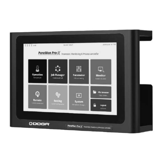
Page 11: Home
2. HOME 2.1 Operator mode Operator can select one of 4 screen menu – Operation, Monitor, System and Login. Login menu requires the password to move to administrator mode There is no setting available in operator mode. Category Description Operation Moves to the OPERATION page Monitor Moves to the MONITOR page... -
Page 12: Administrator Mode
2.2 Administrator mode All settings and job creation is available in admin mode only. Category Description Operation Moves to the OPERATION page Job Manager Moves to the JOB MANAGER page Parameter Moves to the PARAMETER page Monitor Moves to the MONITOR page Remote Moves to the REMOTE page Setting... -
Page 13: Network Configuration
3. NETWORK CONFIGURATION For connection between ParaMon-Pro X and BM, a network can be configured as follows: Category Description The most common type Connection through Internal Through a USB WiFi adapter in ParaMon-Pro X, ParaMon-Pro X is operated in AP mode and connected to BM. Connection through ParaMon-Pro X is connected to BM, using a separate AP. -
Page 14: Connect Through Internal Ap
3.1 Connect through internal AP The most common type. Through a WiFi adapter in ParaMon-Pro X, ParaMon-Pro X is operated in AP mode and connected to BM. The WiFi module in ParaMon-Pro X is operated in AP mode only, not in Station mode. Log into the system in Admin mode. - Page 15 Press [Apply]. As shown in the figure below, WiFi is enabled after searching for the best channel. ParaMon-Pro X instruction manual DOC.60391-01/21...
-
Page 16: Connection Through External Ap
3.2 Connection through external AP Connect ParaMon-Pro X and BM, using a separate AP. This connection type can be used when wider WiFi coverage is needed or a particular feature by the AP is required. The WiFi adapter in ParaMon-Pro X is not operated in Station mode. Therefore, Ethernet wiring is needed for connection between ParaMon-Pro X and a separate AP. - Page 17 Check the IP address by the DHCP server in the following order: Home → System → Network. ParaMon-Pro X instruction manual DOC.60391-01/21...
-
Page 18: Bm Wifi Setup
4. BM WIFI SETUP 4.1 Setup using ParaMon Air (PC) Depending on circumstances, there might be multiple COM ports in the PC. Therefore, it is required to check the COM port numbers connected to the BM before starting the ParaMon Air. Open the Device Manager in the Windows PC. - Page 19 C.Connect the PC with the BM, using the accompanying USB cable. D.Once the BM is connected properly, a new COM port appears in the COM & LPT category. The COM port number can vary depending on configuration. Start the ParaMon Air program. Extend the COM Port List box as shown below: Select the COM port number of BM confirmed in the device manager.
- Page 20 Select the NETWORK tab on the left. Match the SSID and Password settings with ParaMon-Pro X. Press [CLOSE] and finish the connection. M. Remove the BM battery and cut off the power. Connect the BM battery and turn on the power. The BM’s WiFi settings are done.
-
Page 21: Setup Using Paramon-Pro X
4.1 Setup using ParaMon-Pro X Connect ParaMon-Pro X with the BM, using the accompanying USB cable. If successfully connected, the NETWORK SETTNG page appears automatically. ParaMon-Pro X instruction manual DOC.60391-01/21... - Page 22 Connect the battery and switch on the BM. Ensure to connect the USB cable after the system is successfully reset. If switched on after the USB cable is connected when the system is OFF, or the USB cable is connected while the BM is being reset, The NETWORK SETTING page may not appear on the screen.
-
Page 23: Member Tool Management
5. MEMBER TOOL MANAGEMENT To use tools in ParaMon-Pro X, they should be registered as ‘Member Tools’. Able to register up to 8 member tools This section describes how to manage member tools. ParaMon-Pro X instruction manual DOC.60391-01/21... -
Page 24: Register Member Tools
5.1 Register Member Tools A.Press [Login] and log into the system. The default password is “0”. B.As shown in the figure, swipe from top to the bottom. C.Select the EDIT icon for member tool registration. ParaMon-Pro X instruction manual DOC.60391-01/21... - Page 25 ParaMon-Pro X automatically searches all tools accessible on wired and wireless networks and displays target tools on the right table. Check the model No. and serial number on the label or DRIVER INFORMATION page. ParaMon-Pro X instruction manual DOC.60391-01/21...
- Page 26 Select the tool matched by the model No. and serial number on the right table. Press [Register] and register the selected tool on ParaMon-Pro X. The tools on the right list move to the left, and the registration process is done. Press [OK] and end the settings.
-
Page 27: Deregister Member Tools
5.2 Deregister Member Tools A.Press [Login] and log into the system. The default password is “0”. B.As shown in the figure, swipe from top to the bottom. C.Select the EDIT icon for member tool registration. D.Check the model No. and serial number on the label or DRIVER INFORMATION page. ParaMon-Pro X instruction manual DOC.60391-01/21... - Page 28 Select the tool matched by the model No. and serial number on the left table. Press [Release]. Once the confirmation page pops up, press [OK] and deregister the tool from ParaMon-Pro X. Press [OK] and end the settings. ParaMon-Pro X instruction manual DOC.60391-01/21...
-
Page 29: Modify Member Tool Names
5.3 Modify member tool names At member tool registration, tool names are basically formed in the following format: “Tool Type (BM, BMT, etc.) + Serial No.”. It is okay to use the default tool name, but it can be modified for the convenience of tool identification. A.Select the EDIT icon. -
Page 30: Check Member Tool Status
5.4 Check member tool status A.As shown in the figure, swipe from top to the bottom. B.A list of the member tools currently registered on ParaMon-Pro X appears. ParaMon-Pro X instruction manual DOC.60391-01/21... - Page 31 C.The member tool list includes the followings: Category Description Not connected yet Successfully connected Status Connection failed; required to reset the tool The tool occupied by the other ParaMon-Pro X Name Name Serial No. Model Model No. F/W ver Firmware version IP address IP address Port...
-
Page 32: Status Bar
6. STATUS BAR The Status Bar appears on top always and includes the followings: Description Not connected yet Member tool connection (X/Y) Successfully connected X: No. of tools connected Y: Total number of member tools Connection failed; required to reset the tool The tool occupied by the other ParaMon-Pro X Name of the target tool selected Date and present time... -
Page 33: Select Target Tool
7. SELECT TARGET TOOL Since ParaMon-Pro X registers and manages multiple member tools, it is required to specify a target tool on the menu for a certain tool such as Parameter, Monitor and Remote. This section describes how to select a target tool. A. - Page 34 C. If a target tool is selected on the member tool list, the system goes back to the previous page automatically. A target tool is selectable when the tool is normally connected ( A target tool is not selectable if The tool is not connected yet ( The tool is improperly connected ( ), or...
-
Page 35: Parameter
8. PARAMETER Able to manage the parameters of all BM tools registered in ParaMon-Pro X Unless a target tool is specified, the following page appears. Refer to ‘7. Select Target tool’. 8.1 Fastening The system supports a total of 15 preset groups, and each group includes the followings: ParaMon-Pro X instruction manual DOC.60391-01/21... - Page 36 A.Type Torque control / angle monitoring TC/AM Torque values (TARGET) are critical in judging fastening (OK/NG) while angle values are sub-values. Angle control / torque monitoring AC/TM Angle values (TARGET) are critical in judging fastening (OK/NG) while torque values are sub-values.
- Page 37 G.Snug torque Sets the measurement point of angle values used in judging OK/NG. ‘0’ refers to ‘Disabled’. Angle measurement begins as soon as the tool is operated. If not ‘0’, angle measurement starts as soon as the torque reaches the snug torque value. Setting snug torque to a value other than ‘0’.
- Page 38 K.Seating point from target torque (%) Modification not recommended for hard joint Modified recommended for soft joint only The part where target starts to increase when the screw head touches the surface of a target object is called ‘seating point’. For example, in the event of 10.00 kgf.cm of target torque and 40% in seating point from target torque, tool torque starts to increase.
- Page 39 L.Torque rising time (ms) In the above graph, a torque curve rebounds in a V shape after a seating point and rises up to the target torque. Able to adjust the time taken to rise up to target torque after the V-shaped rebound, using ‘torque rising time (ms)’.
-
Page 40: Advanced
8.2 Advanced ‘Advanced’ is comprised of four possible features. Each feature is implemented by a combination of multiple parameters. It provides 15 advanced presets and is paired with fastening preset. Unless otherwise set, default values of ‘Advanced’ are ‘0 (disabled)’. ParaMon-Pro X instruction manual DOC.60391-01/21... -
Page 41: Free Reverse Rotation
8.2.1 Free reverse rotation Able to set reverse rotation up to 20 turns to make the bit spontaneously enter into a screw hole or fastened object hole before fastening the screw. Speed (RPM) Sets reverse speed Angle (turn) Sets reverse angle 8.2.2 Thread tapping The figure above reveals the 4 steps of thread tapping. - Page 42 The figures below reveal graphs displayed after setting thread tapping in ParaMon-Pro X. The torque-angle correlations can be checked depending on the status of angle start from tapping. ParaMon-Pro X instruction manual DOC.60391-01/21...
-
Page 43: Engaging Torque Detection
8.2.3 Engaging torque detection Able to detect a point where the screw is engaged with the screw groove by monitoring torque. To use this feature, engaging torque when the tool is matched with the screw thread should be greater than free-run torque when the tool is activated in the air. Speed (RPM) Sets tool speed until the engaging torque is detected. - Page 44 The figure below reveals graphs displayed after setting engaging torque detection in ParaMon-Pro X. It reveals torque-speed correlations and is able to check 3 speed steps with torque changes. 1.Advanced → Speed for engaging detection 2.Preset → Speed 3.Preset → Ramp-up speed The figure below reveals torque-angle correlations.
-
Page 45: Angle After Torque Up
8.2.4 Angle after torque up After ‘torque-up’ is sensed, an additional action can be set if necessary. Speed (RPM) Angle (degree) After ‘torque-up’ is detected, it rotates at ____ speed by ___ angle in ___ direction. Direction E.g. Screws are not fastened completely for next processing. If needed to maintain a certain degree of fastening, it is able to keep the degree of fastening constant by spinning them reversely by 2 turns (720°) after torque-up detection. -
Page 46: Controller
8.3 Controller If necessary, the settings for the items in the controller can be adjusted. However, it is recommended to use the default settings if possible. A. Driver lock after WiFi disconnect (sec) If WiFi is disconnected, the tool is automatically locked after the elapse of the preset time. B. - Page 47 C. L/F Switch reverse Able to set the Forward/Reverse switch settings inversely. D. Forward RUN time limit (sec) Limits forward operation time; an error occurs if exceeded. Reverse RUN time limit (sec) Limits reverse operation time; an error occurs if exceeded. Motor Stall time limit (sec) At reverse rotation, maximum hold time can be set in a stationary state.
- Page 48 M. Driver model Sets a driver model. Do not randomly alter without discussion with the manufacturer. Such unauthorized alteration may result in incorrect operation and system failure. N. Controller parameter initialize Enter ‘77’ to reset all settings to the default settings. O.
- Page 49 R. Fastening stop error Unless ‘Torque UP’ is detected during ‘Trigger ON – OFF’, this feature decides if ‘Fastening stop error’ alarm should go off. If ‘ON’, operating procedures are as follows: 1.Press the trigger for a while and release to start the tool. 2.If torque is increased after the process 1 above, ‘Fastening stop error’...
- Page 50 W. Screw type If the screw is fastened counterclockwise, it is able to set a screw-fastening direction by preset. Screw ount Able to set the number of screws and use for diverse purposes. In case there are a total of 10 target screws, the screw count is set to ‘10’. Whenever fastened, the screw count is reduced one by one (e.g., 10, 9, 8, …) and saved together with fastening data.
- Page 51 AA. Select backup data type The BM is able to back up event data (up to 65,000 events) in internal memory. Such events saved in the internal memory are classified into various types. If necessary, whether or not they are enabled is set by type, optimizing log data. In addition, it is able to use the limited memory space more efficiently.
-
Page 52: Multi-Sequence
8.4 Multi-sequence Able to program fastening and loosening to a desired pattern in ‘Multi Sequence’. Supports two different patterns (‘A’, ‘B’) and able to program up to 10 steps each. Each step is comprised of a pair of command and parameter. Command Description Parameter... - Page 53 Command Parameter Rotates reversely up to the number of preset Sets the number of reverse turns by 0.1 turn Loosening (0.1 turn) turns 10 = 1 turn (360°) Jump Moves to the preset step No. Sets the target step No. Each multi-sequence has a variable called ‘A’.
-
Page 54: Network
8.5 Network Able to set the WiFi network of the BM; needed to reset the system to apply the new settings Category Description SSID Enters the SSID of the target WiFi AP Password Enters the password of the target WiFi AP Sets an area Country ‘Default’... -
Page 55: Monitor
9. MONITOR Unless the target tool is specified, the following figure appears on the screen. Refer to ‘7. Select target tool’. ParaMon-Pro X instruction manual DOC.60391-01/21... -
Page 56: Graph
9.1 Graph It is able to check the target tool’s fastening data in realtime graph. In addition, it is possible to compare and analyze correlations between two different source data by providing a total of 2 channels and supporting 8 different source data by channel. The source data selectable by channel are as follows: Category Description... - Page 57 Category Description While the above current represents the actual current consumption of the tool, current command refers to target current to control. Current command (mA) In other words, if current and current command are set and compared in two channels, it is able to compare and analyze both actual and target current values.
-
Page 58: I/O
9.2 I/O Able to check the current status of I/O port. If system functions are allocated to the I/O port, function names also appear. ParaMon-Pro X instruction manual DOC.60391-01/21... -
Page 59: Error
9.3 Error The latest 8 errors from the target tool appear. ParaMon-Pro X instruction manual DOC.60391-01/21... -
Page 60: Remote
10. REMOTE 10.1 Output Able to control the level of output port manually. If system functions are allocated to the output port, function names also appear. Useful in checking if properly wired after I/O wiring. ParaMon-Pro X instruction manual DOC.60391-01/21... -
Page 61: Tool
10.2 Tool Able to control a target tool in the distance from ParaMon-Pro X. Category Description Preset Sets the preset of the target tool. Direction Sets a direction for remote control. Able to set the lock by direction if necessary . Lock control The tool may not function if locked in the direction settings. -
Page 62: Setting
11. SETTING 11.1 Operation ParaMon-Pro X instruction manual DOC.60391-01/21... - Page 63 A. Operation mode Whether or not the Assembly Process Control, one of the major features of ParaMon-Pro X, would be enabled is decided. In ParaMon-Pro X, a single assembly process programmed by a user is called, ‘job’. Depending on if the job is used, the mode is classified into ‘With job’ and ‘Without job’. Operation mode With job Without job...
- Page 64 B. Screw count direction Enabled under ‘With job’ mode only. The screw count increases from ‘0’ to total count. Up (1,2,3 …) The screw count represents the number of fastened news. The screw count decreases from total count to ‘0’. Down (…...
- Page 65 G. Skip button access without password Enabled under ‘With job’ mode only. Able to set if a password would be asked when the SKIP button is pressed during job execution. A password not asked. A password asked. H. Back button access without password Enabled under ‘With job’...
- Page 66 Automatically restart job when finished Enabled under ‘With job’ mode only. Able to set if the job would be automatically restarted when all job procedures are done. Automatically restarts at the end of job process. Does not automatically restart at the end of job process. M.
-
Page 67: I/O
11.2 I/O ParaMon-Pro X provides a total of 32 I/O ports (16 ports each) for the purpose of interlocking with external devices. Able to allocate system functions pre-defined in input and output in ‘Setting → I/O’. Unable to use the ports allocated to the system function in input and output steps during job programming. Category Description Input clear all... -
Page 68: Input
11.2.1 Input Unlike output, input is not able to allocate system functions in a redundant manner. The system functions already allocated to other parts are enabled as shown in the figure. Category Description Able to load jobs through external input under the ‘With job’ mode. Job selection 1-8 For more information, refer to ‘11.1 Operation →... -
Page 69: Output
11.2.2 Output Unlike input, output is able to allocate system functions in a redundant manner. Category Description Fastening OK Appears if the fastening results meet preset conditions. Fastening NG Appears if the fastening results do not meet preset conditions. Step OK Appears if the fastening procedures/results of all screws set in the fastening step are OK. -
Page 70: Log
11.3 Log Storage location Sets a log file storage position. Select data field Enabled under ‘Without job’ mode only. Able to select data which appear on the screen. Saves all data in the log file regardless of settings. ParaMon-Pro X instruction manual DOC.60391-01/21... -
Page 71: Barcode - Without Job & Bm Integrated Scanner
11.4 Barcode - without job & BM integrated scanner Enabled under ‘Without job’ mode only. Able to register a code for a change to certain preset by tool. Available in the scanner-integrated BM only. ParaMon-Pro X instruction manual DOC.60391-01/21... - Page 72 A. Code input Select target tools for registration. A scanner is enabled if the trigger is executed twice in a row. If a code is scanned, the registration page along with the scanned code pops up. If necessary, press [Add] and enter the code in person. B.
-
Page 73: Network
11.5 Network A.WiFi Setting to run WiFi AP in ParaMon-Pro X. After editing the settings, press [Apply]. Enters the AP’s SSID SSID Up to 32 letters Enters the password of AP Password At least 8 characters long; able to enter up to 32 characters Band Selects the operating frequency of AP Able to set the AP frequency channels... -
Page 74: Share
11.6 Share FTP Server After editing settings, press [Apply]. Enable/Disable Sets if the FTP server is enabled or disabled. Username Sets the username to be used in logging into the FTP server. Password Sets the password to be used in logging into the FTP server. Able to check the IP address needed to get access to the FTP server in ‘System →... - Page 75 B. Backup data forwarding The backup data received from member tool is transferred to a separate external server connected via Ethernet. After changing the settings, changed settings are updated only by pressing the button “Apply”. Enable/Disable Set enable to mirror backup data on ethernet port. Server IP address Set the IP address of the server to receive the backup data.
-
Page 76: System
11.7 System A. Password Sets a password for ADMIN mode; the default setting is ‘0’. B. Language Currently supports ‘English’ only; other languages to be supported. C. System time Sets system time; able to set ‘min’; ‘sec’ is set to ‘0’. D. -
Page 77: System
12. SYSTEM 12.1 Device info Able to check brief information of ParaMon-Pro X. Able to check serial number and software version and includes a software upgrade feature. ParaMon-Pro X instruction manual DOC.60391-01/21... -
Page 78: Storage
12.2 Storage Internal storage Able to check the space used and free space. Able to examine if micro SD card is inserted and check the space used and free Micro SD space. ParaMon-Pro X instruction manual DOC.60391-01/21... -
Page 79: Network
12.3 Network Ethernet Displays the wired ethernet address. WiFi Displays wireless ethernet (WiFi) address. ParaMon-Pro X instruction manual DOC.60391-01/21... -
Page 80: Job Manager
13. JOB MANAGER Category Description Down Moves the selected job to the bottom by one column Moves the selected job to the top by one column Creates a new job Delete Deletes the selected job Copy Copes the selected job and adds it as a new job Edit Edits the selected job Rename... -
Page 81: Edit Job & Step
13.1 Edit job & step The biggest unit constituting the assembly process control is expressed by multiple sequential steps. Supports up to 1,000 jobs and able to add up to 255 steps per job. 1. Add step Category Description Fastening Adds a fastening procedure, using a member tool Input Enables various extensions, using a total of 16 input ports... - Page 82 2. Edit step list Category Description Down Moves the selected step to the bottom by one column Moves the selected step to the top by one column Delete Deletes the selected step Copy Copies the selected step and adds it as a new step Rename Renames the selected step 3.
-
Page 83: Fastening Step
13.1.1 Fastening step Fastening step supports up to 99 screws: Press [Fastening]. Then, a fastening step is added to the bottom of the step list. Then, a setup page appears on the right. If necessary, press [Rename] and edit the step name. Select a tool for fastening among the member tools. - Page 84 Description If necessary, moves the screen to the left or right Hides the screen to the bottom and views the entire image Able to adjust a pixel unit at registration of screw position Loads an image to be used in screw positioning Sets the index number of the screws to be positioned +Append: adds a new screw to the end +Insert: adds a new screw to the current index position...
- Page 85 ParaMon-Pro X instruction manual DOC.60391-01/21...
-
Page 86: Input Step
13.1.2 Input step Press [Input]. Then, an input step is added to the bottom of the step list. Then, a setup page appears on the right. If necessary, press [Rename] and edit the step name. Select the port to get signals. The ports with system functions are disabled and not selectable. -
Page 87: Output Step
13.1.3 Output step Press [Output]. Then, an output step is added to the bottom of the step list. Then, a setup page appears on the right. If necessary, press [Rename] and edit the step name. Select the port to generate signals. The ports with system functions are disabled and not selectable. -
Page 88: Delay Step
13.1.4 Delay step Press [Delay]. Then a delay step is added to the bottom of the step list. Then a setup page appears on the right. If necessary press [Rename] and edit the step name. Select a delay type. Category Description Time Stops the step process for a certain period of time;... -
Page 89: Message Step
13.1.5 Message step Press [Message]. Then a message step is added to the bottom of the step list. Then a setup page appears on the right. If necessary press [Rename] and edit the step name. If necessary enter texts and send a simple message to an operator. Able to register an image and send a more efficient message if necessary. -
Page 90: Barcode
13.2 Barcode Registers a code and sets jobs to have them automatically loaded through code scanning. Able to register the same code redundantly but executes items with small No. according to priority. Able to load jobs through code scanning in the event that current jobs are absent. Changes code information recorded in the log when code scanning is done during job execution. - Page 91 Edit Edits selected items Select Changes a mode to select multiple items Select all Selects all items Cancel Ends a multiple item selection mode 1. If a code is scanned through USB Scanner or BM built-in scanner, the edit page appears as shown in the figure.
-
Page 92: Operation
14. OPERATION The operation page appears differently depending on operation mode settings (‘With job’ or ‘Without job’). Operation Mode With Job Without Job Uses process control and is operated according to the procedures programmed to a Does not use process control and is able to job. -
Page 93: With Job Mode
14.1 With job mode Category Description Open job Selects a job from the job list and loads. Previous job Loads the previous job according to the sequence of the job list No. Next job Loads the next job according to the sequence of the job list No. Full screen Enables the full screen mode in the fastening or message step. -
Page 94: Fastening Step
14.1.1 Fastening step Description Displays the tool name and preset information in the fastening step. Reveals the last scanned code information; the code is actually recorded in the log. Shows a screw count according to the screw count direction settings. Reveals a total number of screws according to the screw count unit settings. - Page 95 If an image is registered in the fastening step, it is generated in full screen. In terms of a fastening state, ‘OK’ or ‘NG’ is displayed by color depending on settings. If touched in the full screen mode, it is turned off temporarily and switched to the count page. To return back to the full screen mode, press the ‘Full screen’...
-
Page 96: Input Step
14.1.2 Input step The above page appears when four inputs were programmed to ‘Active high’ in the input step. LED light is turned on four enabled ports only. LED light is turned on in input-sensed ports such as No.11 and No.12. LED light is off in non-input ports such as No.13 and No.14. -
Page 97: Output Step
14.1.3 Output step The above page appears when four inputs were programmed to ‘Impulse’ in the output step. LED light is turned on four enabled ports only. ParaMon-Pro X instruction manual DOC.60391-01/21... -
Page 98: Delay Step
14.1.4 Delay step The above page reveals the delay step set by the timer (5 sec.). It is displayed in ‘elapsed / set time’ format. Once the timer reaches the preset time, the page moves to the next step. If the previous step is ‘Message step’, the timer is executed in the background, and the screen keeps displaying a message. - Page 99 The above page reveals the delay step set by the barcode. Once the code is scanned in USB scanner or BM built-in scanner, the page moves to the next step. If the previous step is ‘Message step’, the delay is executed in the background, and the screen keeps displaying a message.
-
Page 100: Message Step
14.1.5 Message step When setting the message step, if an image is already registered, it is displayed in full screen. If touched in the full screen mode, it is turned off temporarily. To return back to the full screen mode press the ‘Full screen’ button. ParaMon-Pro X instruction manual DOC.60391-01/21... -
Page 101: File Browser
15. FILE BROWSER Offers simple file browser features. Available in various situations such as log file backup image file insertion and file move. Supports external storage devices such as USB memory and Micro SD and able to select a storage device if the arrow is pressed. - Page 102 The structure and purposes of the top-level internal storage folder are as follows: Category Description Image Stores image files used in fastening and message step. Stores job files programmed by a user. A space where log files are stored; owns a sub folder in order of year, month and day. Setting Stores preset files.
-
Page 103: Ftp Server
16. FTP SERVER This section describes how to get access to the FTP server. For the FTP client needed to get access to the FTP server, there are various types of programs. This section uses the most widely used freeware ‘Filezilla client’. http://filezilla-project.org/ ParaMon-Pro X instruction manual DOC.60391-01/21... -
Page 104: Connection Via Wifi
16.1 Connection via WiFi 1. Connect to ParaMon-Pro X AP in WiFi-connected PC. 2. Start the Filezilla Client. 3. Enter the WiFi IP address into the host. ParaMon-Pro X’s WiFi always has ‘192.168.131.1’ for address. 4. Enter the FTP server’s username from ‘Setting → Network’. The default value is ‘paramon’. -
Page 105: Connection Via Ethernet
16.2 Connection via ethernet 1. Start the Filezilla Client. 2. Enter the ethernet IP address into the host. Check the ethernet IP address in ‘System → Network’. 3. Enter the FTP server’s username from ‘Setting → Network’. The default value is ‘paramon’. 4. -
Page 106: Backup & Restore
17. BACKUP & RESTORE This section describes backup/restore procedures under two different categories: ParaMon-Pro X and BM. 17.1 ParaMon-Pro X ParaMon-Pro X’s backup and restore features can be available in two types: A. After backing up ParaMon-Pro X’s current settings, the system can be restored to the current state if necessary. At restoration, the file system is overwritten. -
Page 107: Backup
17.1.1 Backup A. Press [P2P] in ‘Setting → System’. B. Select “Save …” and press [OK]. ParaMon-Pro X instruction manual DOC.60391-01/21... - Page 108 C. Set the backup storage position and filename and press [OK] for backup. The filename is automatically created in ‘ProX_YYYYMMDD.p2p’ format. It can be edited if necessary. If stored by specifying an external storage device folder, it would take a relatively long time for backup. It is recommended to store the backup in the internal repository and copy/move it to an external storage device, using ‘15.
-
Page 109: Restore
17.1.2 Restore A. Press [P2P] in ‘Setting → System’. B. Select “Load …” and press [OK]. ParaMon-Pro X instruction manual DOC.60391-01/21... -
Page 110: Bm Parameters
C. Select the file and press [OK]. D. Press [OK] and restart the system. 17.2 BM Parameters BM Parameter’s backup and restore features can be available in two types: A.After backing up BM’s current parameter settings, the system can be restored to the current state if necessary. If BM parameter settings are edited frequently according to operating environments, it is able to edit them collectively, using backup/restore features. -
Page 111: Backup
17.2.1 Backup Press the ‘Backup’ icon of the target tool on the member tool list. Set the backup storage position and filename and press [OK] for backup. The filename is automatically created in ‘Toolname_Model_Fwver.csv’ format. It can be edited if necessary. ParaMon-Pro X instruction manual DOC.60391-01/21... -
Page 112: Restore
17.2.2 Restore Press the RESTORE icon of the target tool on the member tool list. Select the file and press [OK]. ParaMon-Pro X instruction manual DOC.60391-01/21... -
Page 113: Software Upgrade
18. SOFTWARE UPGRADE A. Log into the system in ADMIN mode. B. Select ‘System’ in the ADMIN menu. C. Choose ‘Device info’ on the left. D. Check the current software version and press [Upgrade]. E. Enter the password again. F. Select the target file and press [Upgrade]. G. - Page 114 H. Wait until the process is completed. Once the upgrade is successfully completed, the restart system message pops up. Press [OK] and restart the system. J. Once successfully reset, log into the system in ADMIN mode again. K. Select ‘System’ in the ADMIN menu. L.
-
Page 115: Maintenance
During manufacturing the proper functioning of the unit is checked multiple times. However, if the unit malfunctions, troubleshoot it using this list. Warning All troubleshooting tasks requiring the opening of the box must be performed by DOGA or a company authorised by DOGA. Problem... -
Page 116: Spare Parts
For any spare parts order, contact your DOGA technical sales representative. My client area on www.doga.fr Go to your client area on www.doga.fr,, click “Your contacts”, then select your specific After-sales department contact depending on the device type. 19.4 Hotline 19.4.1 For any questions about the use of the device... -
Page 117: After-Sales Returns
Following this procedure allows you to quickly take charge of your request and reduces the troubleshooting costs. DOGA reserve the right to apply a trade-in discount and to invoice, if applicable, the costs of repairing and packaging. 19.5.1 Download the after-sales return form You can download the return form by following one of these links: http://service.doga.fr/syst/dogatech.nsf/liste/00184... -
Page 118: On-Site Repair
Our services will organize the intervention. 19.7 Warranty DOGA guarantees all his products against any defect in parts or fabrication for a period of 12 months. To benefit from the parts and labor warranty, the following conditions must be respected: ... -
Page 119: Safety
20. SAFETY 20.1 General provisions The instruction manual must be carefully stored in a known place and easily accessible to the potential users of the product. Attention Read this manual and have each operator read it carefully before installing, using or repairing. Make absolutely sure that the operator has fully understood the rules of use and the meaning of any symbols affixed to the product. -
Page 120: Standards
21.1 Importer details Importer: DOGA Adresse: ZA Pariwest 8 avenue Gutenberg CS 50510 78317 MAUREPAS CEDEX - FRANCE 21.2 Markings BM Series Controller Description ParaMon-Pro X Type S/N MM/YYYY XXXX Serial number month/year of production Name of the equipment manufacturer 100-230V 0.4A... -
Page 121: Weee Recycling And End Of Service Life
26.4.1 Collection and recycling scheme In compliance with the French Environmental Code covering professsional Waste Electric and Electronic Equipment (WEEE) (art.R543-195 et seq.), DOGA is a member of ECOSYSTEM, an eco-organization approved by public authorities under the conditions defined by art R543-197. -
Page 122: Appendices
22. APPENDICES 22.1 - Declaration of conformity Description Lien de téléchargement QR code EU declaration of http://service.doga.fr/syst/dogatech.nsf/liste/00283 conformity ParaMon-Pro X 22.2 - Interface port DB44 pin out ROW 1 (1~15) ROW 2 (16~30) ROW 3 (31~44) Pin no Desc Pin no... -
Page 123: Backup Data Forwarding
22.3 - Backup data forwarding Please refer to backup data forwarding function setting describe in [ 11.6. Share ] section. The backup data forwarding function forwards the backup data received from the member tools to the set external server. The data format is based on the Modbus-TCP standard. In general Modbus-TCP-based data communication always operates as a pair of request/response, but in backup data forwarding function, only response is unilaterally transmitted, and the data format is as follows. - Page 124 Download the ultimate version of this user manual via the link below or via QR code: http://service.doga.fr/syst/dogatech.nsf/liste/60391 © DOGA | DOC.60391-12/20 © DOGA | DOC.60391-01/21 ParaMon-Pro X instruction manual DOC.60391-01/21...
Need help?
Do you have a question about the BM Series and is the answer not in the manual?
Questions and answers