
Related Manuals for Epson Technical Manual


Summary of Contents for Epson Technical Manual
- Page 1 MF873 - 03 CMOS 4 - BIT SINGLE CHIP MICROCOMPUTER S5U1C63000H1 Manual (S1C63 Family In-Circuit Emulator)
- Page 2 No part of this material may be reproduced or duplicated in any form or by any means without the written permission of Seiko Epson. Seiko Epson reserves the right to make changes to this material without notice. Seiko Epson does not assume any...
- Page 3 The information of the product number change Starting April 1, 2001, the product number will be changed as listed below. To order from April 1, 2001 please use the new product number. For further information, please contact Epson sales representative.
-
Page 5: Table Of Contents
__________________________________________ 19 CHAPTER OTES ON SING 6.1 Notes on Operations ..................19 6.2 Differences from Actual IC ................19 ________________________________ 20 CHAPTER AINTENANCE AND ARRANTY 7.1 Diagnosis Test ....................20 7.2 Warranty ....................... 20 EPSON S5U1C63000H1 MANUAL (S1C63 FAMILY IN-CIRCUIT EMULATOR) - Page 6 9.1.2 External view of LCD63001 ..............22 9.2 Precautions on Using ................... 23 9.2.1 Notes on operations .................. 23 9.2.2 Difference from an actual IC ..............23 9.3 Connection with Target System ..............24 9.4 Product Specifications ................. 26 EPSON S5U1C63000H1 MANUAL (S1C63 FAMILY IN-CIRCUIT EMULATOR)
-
Page 7: Chapter 1 Introduction
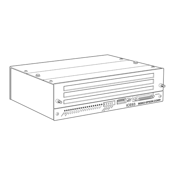
S5U1C63000H1 system. Refer to "S5U1C63000A Manual" for use of the debugging commands. Figure 1.1 shows the external view of the S5U1C63000H1. ∗ The name 'ICE63' on the development tool is the old name of the product. Fig. 1.1 External view of S5U1C63000H1 EPSON S5U1C63000H1 MANUAL (S1C63 FAMILY IN-CIRCUIT EMULATOR) -
Page 8: S5U1C63000H1 Package
CMOS 4-bit Microcomputer S1C63 Family ......S5U1C63000H1 Manual S5U1C63000H1 Manual ............SEIKO EPSON CORPORATION SEIKO EPSON CORPORATION English Japanese English Japanese •S5U1C63000H1 main unit 1 2 3 4 5 6 7 8 RS232C ICE63 SEIKO EPSON CORP. -
Page 9: Component Specifications
5 to 40 °C Operating temperature -10 to 60 °C Storage temperature Operating humidity 35 to 80% Storage humidity 20 to 90% No condensation Resistance to vibration Operating: 0.25 m/S Transportation: 1 m/S EPSON S5U1C63000H1 MANUAL (S1C63 FAMILY IN-CIRCUIT EMULATOR) -
Page 10: Specifications Of Operation Panels
2.4 Specifications of Operation Panels This section explains the operation of each switch. Figure 2.4.1 shows the external view of the panels. 1 2 3 4 5 6 7 8 RS232C ICE63 SEIKO EPSON CORP. (Front view) POWER DC 5V (Rear view) - Page 11 DC 5V DC input connector This is a connector to connect the DC cable of the AC adapter dedicated for S5U1C63000H1. Rear panel POWER Power switch Turns the S5U1C63000H1 power on and off. EPSON S5U1C63000H1 MANUAL (S1C63 FAMILY IN-CIRCUIT EMULATOR)
-
Page 12: Setting The Dip Switch
Note: When the S5U1C63000H1 is started with the self diagnosis on, it takes approx. 5 minuets to be ready for use. Open means that the switch lever is at upper side. On means that it is at lower side. EPSON S5U1C63000H1 MANUAL (S1C63 FAMILY IN-CIRCUIT EMULATOR) -
Page 13: Chapter 3 Connection
To connect with IBM PC/AT and its compatibles, use the 9-pin/25-pin cable. Tightening the connectors with the screws is strongly recommended after the connection. EPSON S5U1C63000H1 MANUAL (S1C63 FAMILY IN-CIRCUIT EMULATOR) -
Page 14: Installing Peripheral Circuit Board (S5U1C63Xxxp)
(1) on the main case by pushing and turning two screws located at both side. (5) The jig has a magnet for keeping under the bottom plate of the case while not in use. EPSON S5U1C63000H1 MANUAL (S1C63 FAMILY IN-CIRCUIT EMULATOR) -
Page 15: Chapter 4 Getting Started
The S5U1C63000H1 executes the target program from the reset address. The PC LEDs (red) indicate the current program counter position during execution. When the SLP or HALT instruction is ex- ecuted, the SLP/HLT LED (yellow) goes on and the PC LEDs (red) stop. EPSON S5U1C63000H1 MANUAL (S1C63 FAMILY IN-CIRCUIT EMULATOR) - Page 16 RAM area, it stops after the access to the incorrect area. (4) The S5U1C63000H1 may takes approx. 5 minuets after it is turned on until it starts execution of the target program. EPSON S5U1C63000H1 MANUAL (S1C63 FAMILY IN-CIRCUIT EMULATOR)
-
Page 17: Chapter 5 Operation And Function Of S5U1C63000H1
S1C63000 CPU and RAM contents at watching points. The monitored result is displayed as on-the-fly information. The S1C63000 CPU can real timely execute the target program while the information is displayed. EPSON S5U1C63000H1 MANUAL (S1C63 FAMILY IN-CIRCUIT EMULATOR) -
Page 18: Break Function
A low level is output when the S1C63000 CPU is suspended (by execution of the HALT or SLP instructions). This terminal also outputs low level during break. STOPOUT output Indicating suspension of CPU operation Running Breaking Fig. 5.3.2 STOPOUT terminal output EPSON S5U1C63000H1 MANUAL (S1C63 FAMILY IN-CIRCUIT EMULATOR) -
Page 19: Display During Execution And During Break
This specification can set one break point only. The above break functions, (1), (2), (3), (4), can be independently specified. When the target program is executed with all specified commands, BP, BS, BD, BR, breaks occur by meeting any condition. EPSON S5U1C63000H1 MANUAL (S1C63 FAMILY IN-CIRCUIT EMULATOR) -
Page 20: Target Interrupt And Break
The maximum value of the TP is 8,191. Trace information TP = 0 Earliest instruction Trace information at any point can be displayed by the TD command. Latest instruction TP = 8,191 EPSON S5U1C63000H1 MANUAL (S1C63 FAMILY IN-CIRCUIT EMULATOR) -
Page 21: Trace Mode
(c) Units of time display Micro second (µsec) (2) Bus cycle count mode (a) Range of cycle measurement 1 bus cycle to (2 -1) bus cycles (= 2∗10 bus cycles) (b) Measurement error 0 cycle EPSON S5U1C63000H1 MANUAL (S1C63 FAMILY IN-CIRCUIT EMULATOR) -
Page 22: Self Diagnosis Function
In the models having a timer and a watch dog timer, the timer is operated only when the target program is executed if the timer is active. Therefore, in the single step operation, a real time counting cannot be done with the timers in the S1C63xxx. EPSON S5U1C63000H1 MANUAL (S1C63 FAMILY IN-CIRCUIT EMULATOR) - Page 23 For instance, when the break at read cycle is set by the break data set command (BD), the dummy read hits the break condition. EPSON S5U1C63000H1 MANUAL (S1C63 FAMILY IN-CIRCUIT EMULATOR)
- Page 24 A register becomes 5 at the point of because the IACK is at low level, and the break is occurred after jumping to the interrupt vector address. EPSON S5U1C63000H1 MANUAL (S1C63 FAMILY IN-CIRCUIT EMULATOR)
-
Page 25: Chapter 6 Notes On Using
I/O terminal. Therefore, the value read on the target program may differ from the value read by the dump command. EPSON S5U1C63000H1 MANUAL (S1C63 FAMILY IN-CIRCUIT EMULATOR) -
Page 26: Chapter 7 Maintenance And Warranty
The self diagnosis test is executed by setting SW8 of the DIP switch to OPEN and starting the debugger after power of the S5U1C63000H1 on. Debugger for E0C63 Ver x.xx Copyright(C) SEIKO EPSON CORP. 199x Connecting with ICE ....done ←... -
Page 27: Chapter 8 Trouble Shooting
The circuit breaker (CB) operates and the power LED goes off when the S5U1C63000H1 power is turned on. - Is target cable connected correctly ? - Is V or V short-circuited on a target ? Refer to "S5U1C63000A Manual" for operations of the debugger. EPSON S5U1C63000H1 MANUAL (S1C63 FAMILY IN-CIRCUIT EMULATOR) -
Page 28: Chapter 9 Specifications Of Lcd63001
This board may be set for each model by loading mask option data (generated by "FOG63XXX" software tool) using the ICE command. 9.1.2 External view of LCD63001 Fig. 9.1.2.1 External view of LCD63001 EPSON S5U1C63000H1 MANUAL (S1C63 FAMILY IN-CIRCUIT EMULATOR) -
Page 29: Precautions On Using
(5) LCD drive voltage An error of the LCD drive voltage of this board is larger than the actual IC. EPSON S5U1C63000H1 MANUAL (S1C63 FAMILY IN-CIRCUIT EMULATOR) -
Page 30: Connection With Target System
Use the connection cables (100-pin/50-pin × 2 flat type, 34-pin flat type) supplied for the connection between the LCD63001 and target systems. mark I/O connection cable CN2-1 (50-pin) CN2-2 To target board (50-pin) (34-pin) To target board Fig. 9.3.1 Connection with target system EPSON S5U1C63000H1 MANUAL (S1C63 FAMILY IN-CIRCUIT EMULATOR) - Page 31 Cannot be connected SEG36 SEG36 Cannot be connected SEG37 SEG37 Cannot be connected SEG38 SEG38 Cannot be connected SEG39 SEG39 Cannot be connected SEG40 SEG40 Cannot be connected SEG41 SEG41 Cannot be connected EPSON S5U1C63000H1 MANUAL (S1C63 FAMILY IN-CIRCUIT EMULATOR)
-
Page 32: Product Specifications
254 mm (wide) × 144.8 mm (depth) × 13 mm (height) Dimension: (including screws) Weight: Approx. 220 g Power supply: DC 5 V ±5%, less than 1 A (supplied from S5U1C63000H1 main unit) LCD cable Onboard connector: KEL8830E-100-170L 3M3431-5002LCSC EPSON S5U1C63000H1 MANUAL (S1C63 FAMILY IN-CIRCUIT EMULATOR) - Page 33 Central Phone: +852-2585-4600 Fax: +852-2827-4346 101 Virginia Street, Suite 290 Telex: 65542 EPSCO HX Crystal Lake, IL 60014, U.S.A. EPSON TAIWAN TECHNOLOGY & TRADING LTD. Phone: +1-815-455-7630 Fax: +1-815-455-7633 10F, No. 287, Nanking East Road, Sec. 3 Northeast Taipei 301 Edgewater Place, Suite 120...
- Page 34 In pursuit of “Saving” Technology, Epson electronic devices. Our lineup of semiconductors, liquid crystal displays and quartz devices assists in creating the products of our customers’ dreams. Epson IS energy savings.
- Page 35 S5U1C63000H1 Manual (S1C63 Family In-Circuit Emulator) ELECTRONIC DEVICES MARKETING DIVISION EPSON Electronic Devices Website http://www.epson.co.jp/device/ First issue February, 1996 Printed March, 2001 in Japan...
Need help?
Do you have a question about the Technical Manual and is the answer not in the manual?
Questions and answers