Sign In
Upload
Download
Add to my manuals
Delete from my manuals
Share
URL of this page:
HTML Link:
Bookmark this page
Add
Manual will be automatically added to "My Manuals"
Print this page
×
Bookmark added
×
Added to my manuals
Manuals
Brands
TECO Manuals
Air Conditioner
TPO42CVWAH
User manual
TECO TPO42CVWAH User Manual
Inverter portable air conditioner
Hide thumbs
1
2
3
4
5
6
7
8
9
10
11
12
13
14
15
16
17
18
19
20
21
22
23
24
25
26
27
28
29
30
page
of
30
Go
/
30
Bookmarks
Advertisement
Quick Links
Download this manual
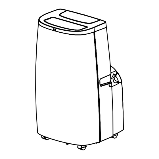
INVERTER PORTABLE AIR CONDITIONER
Cooling Only Model:
TPO42CVWAH
Cooling & Heating Model:
TPO42HVWAH
Air Conditioner.
keep
due to
Previous
Page
Next
Page
1
2
3
4
5
Advertisement
Need help?
Do you have a question about the TPO42CVWAH and is the answer not in the manual?
Ask a question
Questions and answers
Related Manuals for TECO TPO42CVWAH
Air Conditioner TECO TPO47CFAM Owner's Manual
Cooling only (22 pages)
Air Conditioner TECO TPO40CFWBG Owner's Manual
(38 pages)
Air Conditioner TECO TPO35CFALHBE User Manual
(16 pages)
Air Conditioner TECO TPO35CFWCT User Manual
(25 pages)
Air Conditioner TECO TPO20CFBT Care & Maintenance Recommendation
Portable air conditioner (4 pages)
Air Conditioner TECO TPO29CFAT User Manual
Cooling only (24 pages)
Air Conditioner TECO TECOAIR TPO35HFWDT User Manual
(40 pages)
Air Conditioner TECO TPO35HFWDT Care & Maintenance Recommendation
Portable air conditioner (4 pages)
Air Conditioner TECO TPO47CFBT Manual
(17 pages)
Air Conditioner TECO TPO26CFWAO User Manual
(26 pages)
Air Conditioner TECO TPO42HVWAH User Manual
Inverter portable air conditioner (30 pages)
Air Conditioner TECO TECOAIR TPO41CFWUDT User Manual
(40 pages)
Air Conditioner TECO TWS-TSO24HFEC User Manual
Fixed speed split systems (18 pages)
Air Conditioner Teco TWW22CFAGJBB User Manual
Window-wall type room air conditioner (21 pages)
Air Conditioner TECO TWS-TSO26HFFT Owner's Manual
(20 pages)
Air Conditioner TECO TWSM20HVEM User Manual
Inverter multi split type air conditioner (8 pages)
This manual is also suitable for:
Tpo42hvwah
Print
Rename the bookmark
Delete bookmark?
Delete from my manuals?
Login
Sign In
OR
Sign in with Facebook
Sign in with Google
Upload manual
Upload from disk
Upload from URL


Need help?
Do you have a question about the TPO42CVWAH and is the answer not in the manual?
Questions and answers