Advertisement
Quick Links
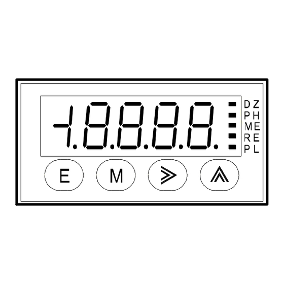
Instruction Manual for MODEL A8X1B-0X
CAUTION
!
(1)
Applying a voltage or current exceeding its maximum permissible value
may cause the unit to be damaged.
(2)
Always use the unit within the specified voltage range: otherwise, it may
cause a fire, electric shock or personal/equipment damage.
(3)
For the purpose of functional improvement, the information written herein
may be changed without prior notice.
(4)
Information contained herein is considered accurate to the best of our
knowledge. If you have any question or comment on the information,
please contact us or our distributor.
(5)
Read this manual carefully and thoroughly before starting to operate the
unit, and keep the manual available for future reference.
1. Before Using the Unit
Thank you for purchasing our A8000 Series Digital Panelmeter. Please
make sure that the operator who uses the panelmeter keeps the manual
on hand. Also, the meter should be checked upon receipt for damage
that might have occurred while in transit. Should the product be dam-
aged or any accessory be missing, notify your sales representative or
our sales office directly.
1.1 Model and Suffix Code Configuration
The model and suffix code of the A8000 series are as shown below.
Check that the product received matches the one you selected when
ordering.
1.2 Checking the Accessories
The A8000 series accessories include one copy of this Operation Manual
and one unit label.
*when BCD is selected by the option,BCD connector(Card edge type
26P)is attached.
2. Mounting Method
2.1 Panel Cutout Size
Panel cutout for mounting the A8000 series digital panelmeter is as shown
below:
+0.5
45.0
-0
MIN 57
* Recommended panel thickness: 1 to 8 mm
2.2 External Dimensions
48.0
3.8
85.
89.
2.3 How to Mount the Unit on the Panel
With the mounting bands detached from the main unit, insert the main unit
into the opening in a panel from the front of the panel, and then attach the
mounting bands to the main unit from the rear of the panel for fixing.
CAUTION
!
(1)
Do not install the unit where it is exposed to dust, particles, chemicals
harmful to electric components, corrosive gases, etc.
(2) When this unit is installed inside other equipment, pay attention to the heat
radiation and keep the heat inside the equipment 50°C or below.
(3) Exercise care so that the product is not subject to vibrations or shocks.
3. Terminals and Connections
(There is no BCD output connector when
BCD output connectors
this machine selects it only for the display.)
1
3
5
7
9
11 1
13 1
15
2
4
6
8
10
16
18
2
4
Input section
Lower terminals
: Input terminal HI (+ input terminal of 1V-rane )
: Input terminal HI (+ input terminal of 2A-range)
: Input terminal LO (- input terminal)
Make input signal wires as short as possible and keep them away
from other signal wires.
Use two-core shielded cables in locations with a lot of external
noise and connect the external sheaths to the LO side of the signal
source at one point.
If harmonic noise is superimposed on an input signal, use a low-
pass filter at the time of input. However, care must be exercised
depending on the usage conditions because a delay in response
time is caused in time constant.
,
: NC terminals
Do not connect anything to the NC terminals.
: Power terminal (DC POWER 0 V)
: Power terminal (DC POWER +V)
The A8000 series panelmeter has no power switch; connecting it to
a power source causes it to be operable immediately.
17
19
21
23
25 2
20
22
24
6
Power receiving section
1/8
Advertisement

Related Manuals for WATANABE ELECTRIC INDUSTRY A8000 Series


Summary of Contents for WATANABE ELECTRIC INDUSTRY A8000 Series
- Page 1 1.1 Model and Suffix Code Configuration Do not install the unit where it is exposed to dust, particles, chemicals The model and suffix code of the A8000 series are as shown below. harmful to electric components, corrosive gases, etc. Check that the product received matches the one you selected when (2) When this unit is installed inside other equipment, pay attention to the heat ordering.
- Page 2 Instruction Manual for MODEL A8X1B-0X Upper terminals (only for units with BCD outputs) 4.4 Shift to the Parameter Setting Mode This machine become it if there are neither BCD output nor External control when selecting it only for the display. Measurement operation ENA D.COM 8 OVER...
- Page 3 Instruction Manual for MODEL A8X1B-0X 4.6.2 Setting Scaling Data (11) Press the Mode key to move to moving averaging count Scaling data is a group of parameters relating to measurements such as setting. (12) Set the number of moving averaging times using the Increment scaling or decimal points.
- Page 4 * To clear the display shift function, set "0." 5.2 Monitoring Mode The A8000 series can display the maximum value, minimum value, the difference between them (maximum value – minimum value), and input values in the main display. Pressing the Increment key with the Enter key held down causes the panelmeter to enter the display status in each mode.
- Page 5 Instruction Manual for MODEL A8X1B-0X approximately one second allows you to clear the display value. Press 6.4 Control Terminal Levels the Enter key to return to the normal indication. (The next time you enter The levels of each control terminal are as shown below: the monitoring mode, the mode you were in when you exited on the “0”...
- Page 6 Instruction Manual for MODEL A8X1B-0X 8. List of the Parameters 8.1 Condition Data 8.2 Scaling Data...
- Page 7 Instruction Manual for MODEL A8X1B-0X 9. Error Messages Error Display Description How to Recover or Remedy An input value or display value Use the panelmeter within the specified measurement and display has exceeded the ranges. measurement range. Microcomputer is waiting for Check if the number of averaging times is set to an appropriate value.
- Page 8 Instruction Manual for MODEL A8X1B-0X...
Need help?
Do you have a question about the A8000 Series and is the answer not in the manual?
Questions and answers