Table of Contents
Advertisement
Quick Links
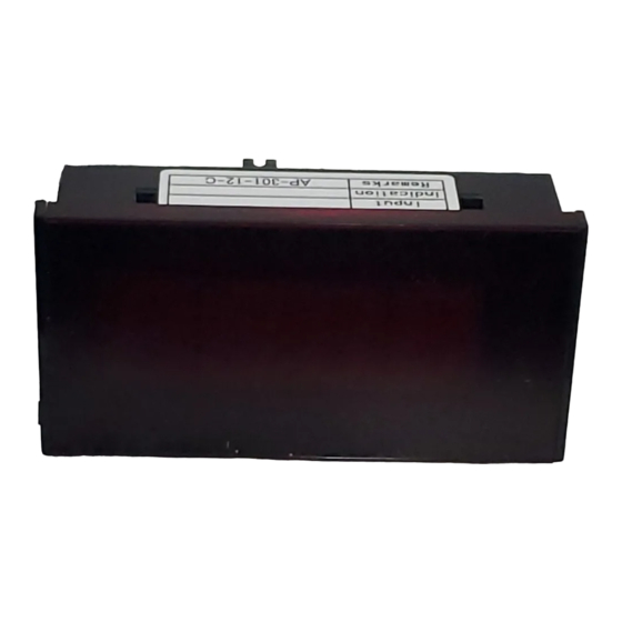
DIGITAL PANEL METER
MODEL AP-301 Series
INSTRUCTION MANUAL
(1) The application of voltage or current exceeding its maximum
allowable value to the input terminals may result in instrument
damage.
(2) The supply of power out of its allowable range may cause fire,
electric shock or instrument failure.
(3) The content of this manual may subject to change without prior
notice for product improvement.
(4)The manual is carefully prepared. However, if any question arises,
or any mistake, omission or suggestion is found in the content
of this manual, contact your nearest our sales agent.
(5) After read this manual, please keep it as anytime can see.
1.OUTLINE
The AP-301 Series digital panel meter is thin and light meter uses
only 3-1/2 digits. The meter uses a 5V power supply driving and
has large LED(Light Emitting Diode)numeric display elements
(Heght:14.2mm)which are easy to see in spite of the small case.
The display has holding and blanking functions and can show a
maximum value of 1999. The circuit largely consists of an
independently developed LSI, which is more reliable than hybrid
integrated circuit.
1 to 5V input, boards for external set screws, a terminal for a
mother board fixture, a power source isolation board and other
options can be provided as required by the customer.
2.SPECIFICATIONS
●DC Voltage Measurement
Model and
Measuring
Range Codes
Range
AP-301-11
±199.9mV
AP-301-12
±1.999V
AP-301-13
±19.99V
AP-301-14
±199.9V
Accuracy:±(0.1% of rdg +1digit)(23℃±5℃ , 35 to 85% RH)
●Specification: DC Voltage Measurement
Model and
Measuring
Display
Range Codes
Range
AP-301-1V
1 to 5V
0 to 1999
Accuracy:±(0.1% of rdg +1digit)(23℃±5℃ , 35 to 85% RH)
●Model Configuration
Caution
Max.
Input
Max.allowable
Resolution
Impendance
Input Voltage
100μV
100MΩ
1mV
100MΩ
10mV
10MΩ
100mV
10MΩ
Input
Max.allowable
Impendance
Input Current
Approx 1MΩ
WATANABE ELECTRIC INDUSTRY CO., LTD.
3.COMMON SPECIFICATIONS
Measurement Function
Operation Method
Input Circuit
Input Bias Current
Sampling speed
Normal Mode Noise
Rejection Ratio
Max. Number of Display
Digit
Overange Alarm
Display
Polarity
Polarity Display
External Control
Operating tenparature/
humidity
Power supply
Power Consumption
Dimensions
Weight
Dielectric strength
Insulation resistance
Accessories
4.HANDLING
4-1 Mounting
1)Panel mounting
Make a rectangular cutout as shown in Fig.1, insert the
instrument from the front into the mainframe panel as shown in
Fig.2.(Specify the panel thickness 1.0 to 4.0mm)
±100V
2)Removing from the panel
±100V
Push the instrument to the panel, holding the hook(Fig.2) with
±250V
the thumb and middle finger.
±500V
4-2 Connector Connection
Insert the provided connector into the rear of the panel meter.
・Operates when LO(terminal 2)
±100V
and 0V(terminal 8) are
Connected.
:DC Voltage measurement
:Dual slope integuration
:Single-ended type
:50pA(Typical)
:Approx. 2.5 times/sec.
:40dB(NMR)(Typical)(50Hz/60Hz)
:1999
: For input signal exceeding maximum
display; 1999 flashes for each digit.
:LED (Light emitting diode),Numeric
elements, Height 14.2mm
:Automatic polarity selection.
:When input signal is negative,
"-" sigh is displayed
: ・ Hold:Short-circuit HOLD(terminal 4)
and 0V(terminal 8).
・Blanking:Short-circuit
BL(terminal 3) and 0V(terminal 8)
・Decimal point setting:
Short-circuit the decimal point
1
terminals 10
(terminal 7),
10
2
(terminal 6), 10
3
(terminal 5) to
0V(terminal 8)
: 0 to 50℃
35 to 85%RH(Nodew-Condense)
: DC; 5V ±5%
:400mW
:72mm(W)×36mm(H)×29mm(D)DIN size
:Approx. 35g
: Input terminal(LO)/common for AC1500V
1 minute
:DC 500V more than 100MΩ at above
terminals
: Instruction manual, Connector
BL(Blanking)
HOLD
(3/4)
Advertisement
Table of Contents

Related Manuals for WATANABE ELECTRIC INDUSTRY AP-301 Series


Summary of Contents for WATANABE ELECTRIC INDUSTRY AP-301 Series
- Page 1 Accessories : Instruction manual, Connector 1.OUTLINE 4.HANDLING The AP-301 Series digital panel meter is thin and light meter uses 4-1 Mounting only 3-1/2 digits. The meter uses a 5V power supply driving and 1)Panel mounting has large LED(Light Emitting Diode)numeric display elements Make a rectangular cutout as shown in Fig.1, insert the...
- Page 2 Fig.3. delivery. Any defect which occurs in this period and is undoubtedly 5)Blanking caused by Watanabe Electric Industry faults will be remedied free By shorting the BL(terminal 3) and 0V (terminal 8), the numeric of charge.
- Page 3 Temperature :Offset displayed-value OPTIONAL BOARDS coefficient TYP. ±0.1-digit/℃ Max. ±0.5-digit/℃ Full scale displayed-value FOR MODEL AP-301 SERIES TYP. ±0.1-digit/℃ Max. ±0.5-digit/℃ INSTRUCTION MANUAL Operating temperature :0 to 50℃ Power supply 5V DC ±5% : Power consumption :600mW(TYP) (When connected to the...
- Page 4 Any defect which occurs in this period and is undoubtedly AP-301-14-C ±199.9V 100mV ±500V caused by Watanabe Electric Industry faults will be remedied free 1MΩ of charge. This warranty does not apply to the board showing abuse or damage 5-2 Input/output terminal connection diagram which has been altered or repaired by others except as authorized by Watanabe Electric Industry.
Need help?
Do you have a question about the AP-301 Series and is the answer not in the manual?
Questions and answers